1
ODT
Test-bench
LabView Modules User Manual
Doc. No.: GEN-MAN-ESO-21110-0028
Issue: 1D2
Date: 05.03.2008
Author(s):
E. Müller, S. Deiries……………………………
Name
Approved by:
Date
Signature
D. Baade……………………………………………….
Name
Date
Signature
………………………………………………………..
Name
Date
Signature
ESO, Karl-Schwarzschild-Str. 2, 85748 Garching bei München, Germany
ODT Test-bench:
LabView Modules User Manual
Doc:
Issue:
Date:
Page:
GEN-MAN-ESO-21110-0028
1D2
05.03.08
2 of 135
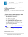
CHANGE RECORD
ISSUE
DATE
1D0
1D1
1D2
28.02.2008
29.02.2008
05.03.2008
SECTION/PARA.
AFFECTED
All
All
All
REASON/INITIATION
DOCUMENTS/REMARKS
New document
Layout changes
Changes from E. Müller
ESO, Karl-Schwarzschild-Str. 2, 85748 Garching bei München, Germany
ODT Test-bench:
LabView Modules User Manual
Doc:
Issue:
Date:
Page:
GEN-MAN-ESO-21110-0028
1D2
05.03.08
3 of 135
TABLE OF CONTENTS
1
2
3
Scope ........................................................................................................................ 5
Introduction................................................................................................................ 5
Applicable and Reference Documents ...................................................................... 5
3.1
Applicable Documents (see also in the individual modules).............................. 5
3.2
Reference Documents....................................................................................... 5
4
LabView Modules ...................................................................................................... 6
4.1
Acquisition Setup............................................................................................... 6
4.2
Device Driver Setup ........................................................................................ 20
4.3
Interface for the Keithley 6514 Electrometer ................................................... 34
4.4
Interface for the Keithley 486 Picoammeter .................................................... 37
4.5
Interface for the Keithley 2100 USB Digital Multimeter ................................... 40
4.6
Interface for the Motorized filter wheel (Newport Model 74041)...................... 44
4.7
Interface for the Monochromator MSH301 ...................................................... 49
4.8
Interface for the Newport Power Supply (Model 69931).................................. 60
4.9
Interface for the Newport ESP 300 Motion Controller ..................................... 66
4.10 Interface for the Newport ITL 09 Motion Controller ......................................... 72
4.11 Interface for the Newport MM 4000 Motion Controller..................................... 78
4.12 Interface for FIERA.......................................................................................... 84
4.13 Interface for PULPO (rev 1.0).......................................................................... 97
4.14
Interface for the BOC Edwards TIC.............................................................. 108
4.15 Interface for the USB Interface Board ........................................................... 113
4.16 Interface for automated data acquisition ....................................................... 117
ESO, Karl-Schwarzschild-Str. 2, 85748 Garching bei München, Germany
ODT Test-bench:
LabView Modules User Manual
Doc:
Issue:
Date:
Page:
GEN-MAN-ESO-21110-0028
1D2
05.03.08
4 of 135
INTENTIONALLY LEFT BLANK
ESO, Karl-Schwarzschild-Str. 2, 85748 Garching bei München, Germany
ODT Test-bench:
LabView Modules User Manual
Doc:
Issue:
Date:
Page:
GEN-MAN-ESO-21110-0028
1D2
05.03.08
5 of 135
1 Scope
This document describes the LabView modules of the new AO test-bench in Laboratory
051. Its functionality and architecture are given.
2 Introduction
This document explains the new LabView drivers and functions of the ODT test-bench
programmed by Eric Müller.
It also should serve as a user manual.
3 Applicable and Reference Documents
3.1 Applicable Documents (see also in the individual modules)
User Manuals of test-bench devices (paper and CD-documentation):
- ORIEL ¼ M MONOCHROMATOR Model MSH301 (Manual)
- ORIEL Monochromator Utility Software Version 3.3
- ORIEL 10 – 100W Lamp Housing LSH101 (Manual)
- ORIEL 100 W Arc Lamp Power Supply LSN110 (Manual)
- Keithley Model 6514 System Electrometer
- Keithley Safety Standards Conformance Information
- Keithley Software Utility ELNX-852 Version C02
- Keithley Low-Current/High Resistance Product Information LCHR-950-01
REV.D
- Newport ESP Motion Controller Configuration Procedure Version 3.01
- Newport High-Performance Mid-Range Travel Linear Stage User’s Manual
- Edwards EXPT Pumping Station & TIC Manual and Software
- NGC User’s manual and Software documentation:
http://www.eso.org/projects/ngc
- FIERA User’s Manual and Software documentation:
ftp://ftp.eso.org/pub/vlt/vlt/pub/releases/JAN2006/vol-4/VLT-MAN-ESO-136401388.pdf
- PULPO User’s Manual: http://www.eso.org/projects/odt/pulpo/pulpo.html
- Jumo Imago 500 User’s Manual
- ODT test-bench documentation:
http://www.eso.org/projects/odt/CCDtestbench/index.html
3.2 Reference Documents
Doc. No.: VLT-MAN-ESO-xxxxx-xxxx New AO test-bench in 051: Assembly and
Programming Instructions, S. Deiries, ESO
ESO, Karl-Schwarzschild-Str. 2, 85748 Garching bei München, Germany
ODT Test-bench:
LabView Modules User Manual
Doc:
Issue:
Date:
Page:
GEN-MAN-ESO-21110-0028
1D2
05.03.08
6 of 135
4 LabView Modules
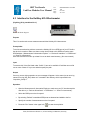
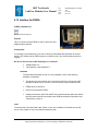
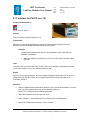
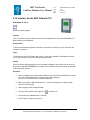
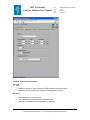
4.1 Acquisition Setup
(Acquisition_Setup.vi)
Purpose
This VI (Global variable) is used to set up for a data acquisition at the AO test bench in 051.
Prerequisites
It is strongly recommended to verify parameters before one of the following VI´s is started:
•
•
•
“LabViewPrism_New testbench.vi”
“FIERA_standalone.vi”
“MasterPanel2.0.vi”
Hardware
The described functionality for this VI is only available in case of the following
hardware configuration:
•
If you intend to use the internal monochromator shutter, connect the USB
interface board to PULPO and verify that the hardware configuration is the same
as described in this manual.
•
In order to write “Weather station data” into the FITS header the weather station
WS 2300 has to be turned on and connected to the serial port which can be
specified in the “Heavy Weather” software (“Setup” >> “Global” >> “COM Port
Nb.”).
Furthermore the path to the data file (“ws_newdata.csv”) which is created by the
“Data Acquisition Software – V2.93.17” and later read out by LabView has to be
specified in the “DeviceDriver_Setup.vi”.
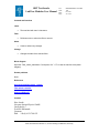
Operation
•
In order to change settings right click on the control and select “Data Operations” >>
“Make current value default” and save the VI (“File” >> “Save” or “Ctrl” + “S”).
•
In order to save the whole setup, press “Edit” >> “Make Current Values Default” and save
the VI (“File” >> “Save” or “Ctrl” + “S”).
ESO, Karl-Schwarzschild-Str. 2, 85748 Garching bei München, Germany
ODT Test-bench:
LabView Modules User Manual
Doc:
Issue:
Date:
Page:
GEN-MAN-ESO-21110-0028
1D2
05.03.08
7 of 135
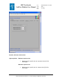
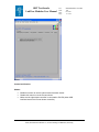
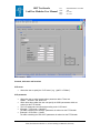
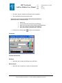
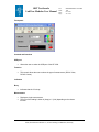
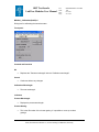
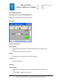
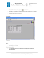
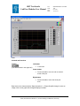
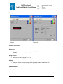
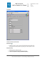
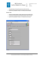
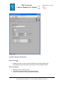
Front panel
At the beginning of an acquisition
Controls, indicators and functions
Lock door in lab 051 if closed
•
If enabled the test bench door is locked (if it is closed) at the beginning of a data
acquisition using the “MasterPanel2.0.vi”.
Check communication with monochromator
•
If enabled a monochromator (MSH 301) communication check is performed at
the beginning of a data acquisition.
ESO, Karl-Schwarzschild-Str. 2, 85748 Garching bei München, Germany
ODT Test-bench:
LabView Modules User Manual
Doc:
Issue:
Date:
Page:
GEN-MAN-ESO-21110-0028
1D2
05.03.08
8 of 135
Check communication with Keithley electrometer
•
A Keithley communication check is performed before the data acquisition begins.
Clear directory on odta<X> before an exposure is
taken (strongly recommended)
•
If enabled all FITS files in the "Path to FITS file on odta<X>" (See "Files") are
deleted before an exposure is taken.
Reboot FIERA (recommended)
•
If enabled FIERA is rebooted at the beginning of an acquisition
("MasterPanel2.0.vi")
Wait until CCD Temperature has reached < Set point temperature >K
•
If enabled the "MasterPanel2.0.vi" waits for the cryostat to cool down or warm up
to the temperature which is specified before the acquisition is started.
Wait until CCD Temperature has reached < Set point temperature >K
•
This is the set point for the heaters 1 and 2 (PULPO).
Send a complete setup to the FIERA software before an exposure is
taken (recommended)
•
The following command is send to the FIERA software before an exposure is
taken:
msgSend $RTAPENV fcdcon_$CCDNAME SETUP "-file fcdSetupComplete.det"
ESO, Karl-Schwarzschild-Str. 2, 85748 Garching bei München, Germany
ODT Test-bench:
LabView Modules User Manual
Doc:
Issue:
Date:
Page:
GEN-MAN-ESO-21110-0028
1D2
05.03.08
9 of 135
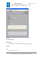
During acquisition
Controls, indicators and functions
Check test bench lamp status
•
•
If enabled the test bench’s lamp controller (Radiometric Power Supply Model
69931) is read out to determine the status of the lamp (turned on/off).
If the lamp is turned of a window appears to ask for further instructions. If the
lamp was turned on at the beginning of the acquisition and breaks down later the
same window appears.
Check if door in lab 051 is closed
•
Allows the user to make sure that the test bench door is closed for the duration of
the data acquisition. If the door is opened the acquisition is paused and a window
appears.
ESO, Karl-Schwarzschild-Str. 2, 85748 Garching bei München, Germany
ODT Test-bench:
LabView Modules User Manual
Doc:
Issue:
Date:
Page:
GEN-MAN-ESO-21110-0028
1D2
05.03.08
10 of 135
Check room light conditions
•
•
If enabled the acquisition is paused if the room light is turned on.
A window appears to ask for further instructions.
Action if an exposure fails
•
•
Allows the user to select how LabView applications react on failed exposures.
Either a window appears to ask for further instructions by the user or the
exposure is taken once more using the same parameters as before.
Pause before dark acquisition starts to mount the metallic cover
•
If enabled the user is asked to mount the metallic cover before the "Dark current"
acquisition ("MasterPanel2.0.vi") begins.
ESO, Karl-Schwarzschild-Str. 2, 85748 Garching bei München, Germany
ODT Test-bench:
LabView Modules User Manual
Doc:
Issue:
Date:
Page:
GEN-MAN-ESO-21110-0028
1D2
05.03.08
11 of 135
Miscellaneous
Controls, indicators and functions
Light acquisition
Maximum exposure time
•
Allows the user to specify the max. exposure time [s] for flat
field images.
Minimum exposure time
•
Allows the user to specify the min. exposure time [s] for flat
field images.
ESO, Karl-Schwarzschild-Str. 2, 85748 Garching bei München, Germany
ODT Test-bench:
LabView Modules User Manual
Dark acquisition
Doc:
Issue:
Date:
Page:
GEN-MAN-ESO-21110-0028
1D2
05.03.08
12 of 135
Maximum exposure time
•
Allows the user to specify the max. exposure time [s] for
dark exposures.
Minimum exposure time
•
•
Allows the user to specify the min. exposure time [s] for dark
exposures.
Remember that bias exposures are also dark exposures
with an exposure time of 0 seconds. Therefore the minimum
should be 0 seconds.
FITS header
ESO, Karl-Schwarzschild-Str. 2, 85748 Garching bei München, Germany
ODT Test-bench:
LabView Modules User Manual
Doc:
Issue:
Date:
Page:
GEN-MAN-ESO-21110-0028
1D2
05.03.08
13 of 135
Controls, indicators and functions
Write comments to FITS header
•
•
If enabled the following data are written into the FITS header:
Example:
Readout mode
Type of exposure
CCD window
Lamp power [W]
Door (Test bench)
MonoShtr: Tclose-Topen [s]
Diode_Lab [V]
CCD_Name
CCD_Model
CCD_Grade
CCD_Serial number
CCD_Pixel size [um]
CCD_photosensitive pixels
CCD_Number of outputs
/9
/ Normal
/ Xstart:2210 Ystart:1 Xend:4200 Yend:510
/ 100
/ closed
/ Monochromator shutter not used
/ 1.278189E-1
/ DMarc
/ CCD1:default CCD2:default
/ CCD1:default CCD2:default
/ CCD1:0 CCD2:0
/ CCD1:15 x 15 CCD2:15 x 15
/ CCD1:0 CCD2:0
/ CCD1:2 CCD2:2
Write header to text file
•
If enabled the header of each FITS file is written to a text file named "<FITS file
name>_HDU.txt" and saved to the same location where the FITS file is stored.
<device>data
•
If enabled the data gathered by either PULPO or JUMO (“device”) is written into
the FITS header: Temp.(CCD1) [K]; Temp.(CCD2) [K]; Vacuum [mbar]
Weather station data
•
•
If enabled the latest readings stored in the data file "ws_newdata.csv", which is
specified in the "DeviceDriver_Setup.vi" is written into the FITS header.
The file "ws_newdata.csv" is created by the "Data Acquisition Software V2.93.17".
Photocurrent (integrating sphere)
•
If enabled the photocurrent measured in the integrating sphere is written into the
FITS header.
Volts (Diode: lab)
•
If enabled the voltage of the diode located in lab 051 (measured by the Keithley
2100) is written into the FITS header.
ESO, Karl-Schwarzschild-Str. 2, 85748 Garching bei München, Germany
ODT Test-bench:
LabView Modules User Manual
Doc:
Issue:
Date:
Page:
GEN-MAN-ESO-21110-0028
1D2
05.03.08
14 of 135
Monochromator data
•
•
If you select a monochromator (MSH301 or MS257), its data are written into the
FITS header.
These are: Wavelength [nm]; Density; Bandwidth [nm]; Color filter; Readout
mode; Type of exposure
Test bench lamp performance [W]
•
If enabled the performance [W] of the test bench lamp is written into the FITS
header.
Files
ESO, Karl-Schwarzschild-Str. 2, 85748 Garching bei München, Germany
ODT Test-bench:
LabView Modules User Manual
Doc:
Issue:
Date:
Page:
GEN-MAN-ESO-21110-0028
1D2
05.03.08
15 of 135
Controls, indicators and functions
Test bench data
•
•
The base path (a folder or drive) to the data produced by LabView applications.
This path must already exist!
Relative path to acquisition data
•
Data acquired by the "MasterPanel2.0.vi" is saved in this directory:
<Test bench data>\<Relative path to acquisition data>
•
For example: <Test bench data> = F:\
<Relative path to acquisition data> =DMarc\AphroditeL
•
The fits files are saved in the existing folder: F:\DMarc\AphroditeL
•
This folder must contain the following structure:
ESO, Karl-Schwarzschild-Str. 2, 85748 Garching bei München, Germany
ODT Test-bench:
LabView Modules User Manual
Doc:
Issue:
Date:
Page:
GEN-MAN-ESO-21110-0028
1D2
05.03.08
16 of 135
Relative path to logs
•
Error logs as well as telnet logs are saved in this existing directory:
<Test bench data>\<Relative path to logs>
•
For example: <Test bench data> = F:\DMarc\
<Relative path to logs> =Logs20.01.08
•
The logs are saved in the existing folder: F:\DMarc\Logs20.01.08
Relative path to manual CCD exposures
•
If you take images with the "FIERA_standalone.vi" these images are saved in the
existing directory: <Test bench data>\<Relative path to manual CCD exposures>
•
For example: <Test bench data> = F:\
<Relative path to manual CCD exposures> =DMarc\test_images
•
The fits file is saved in the existing folder: F:\DMarc\test_images
Path to FITS file on odta<X>
•
This is the directory where images taken by FIERA are saved. LabView picks up
and afterwards deletes images in this directory.
•
Example: "/net/te2/fieramgr/INS_ROOT/SYSTEM/DETDATA"
ESO, Karl-Schwarzschild-Str. 2, 85748 Garching bei München, Germany
ODT Test-bench:
LabView Modules User Manual
Doc:
Issue:
Date:
Page:
GEN-MAN-ESO-21110-0028
1D2
05.03.08
17 of 135
Shutter
Control and function
Shutter
•
•
•
Enable this control to use the internal monochromator shutter.
Disable this control to use the Prontor shutter.
Make sure the right shutter controller is connected to PULPO (either USB
interface board or the Prontor shutter controller).
ESO, Karl-Schwarzschild-Str. 2, 85748 Garching bei München, Germany
ODT Test-bench:
LabView Modules User Manual
Doc:
Issue:
Date:
Page:
GEN-MAN-ESO-21110-0028
1D2
05.03.08
18 of 135
CCD window
Controls, indicators and functions
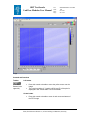
CCD window (Xstart; Xend; Ystart; Yend)
•
•
•
Defines the dimensions of the CCD window which is used to determine the offset
and the ADU mean level during a data acquisition with the “MasterPanel2.0.vi”
Please refer to the graphic on the right
In order to select the whole CCD image:
Xstart = 0
Xend = -1
Ystart = 0
Yend = -1
Offset
•
If "Automatic offset determination" is disabled the user can specify an offset.
ESO, Karl-Schwarzschild-Str. 2, 85748 Garching bei München, Germany
ODT Test-bench:
LabView Modules User Manual
Doc:
Issue:
Date:
Page:
GEN-MAN-ESO-21110-0028
1D2
05.03.08
19 of 135
Automatic offset determination
•
If enabled the offset is determined automatically by taking a bias exposure
followed by a mean level calculation in the CCD window which is specified
above.
SubVI´s
None
Block Diagram
None
ESO, Karl-Schwarzschild-Str. 2, 85748 Garching bei München, Germany
ODT Test-bench:
LabView Modules User Manual
Doc:
Issue:
Date:
Page:
GEN-MAN-ESO-21110-0028
1D2
05.03.08
20 of 135
4.2 Device Driver Setup
(DeviceDriver_Setup.vi)
Purpose
This VI (Global variable) is used to set device driver specific parameters.
You will only have to verify these parameters if you intend to use one of the VI´s listed under
“Prerequisites”
Prerequisites
It is strongly recommended to verify parameters before one of the following VI´s is started:
•
•
•
•
•
“LabViewPrism_New testbench.vi”
“FIERA_standalone.vi”
“MasterPanel2.0.vi”
“MSH301_standalone2.0.vi”
“JUMO_standalone2.0”
Hardware
The described functionality for this VI is only available in case of the following
hardware configuration:
•
If you intend to use the internal monochromator shutter, connect the USB
interface board to PULPO and verify that the hardware configuration is the same
as described in this manual.
•
In order to write “Weather station data” into the FITS header the weather station
WS 2300 has to be turned on and connected to the serial port which is specified
in the “Heavy Weather” software (“Setup” >> “Global” >> “COM Port Nb.”).
Furthermore the path to the data file (“ws_newdata.csv”) which is created by the
“Data Acquisition Software – V2.93.17” and later read out by LabView has to be
specified in the “DeviceDriver_Setup.vi”.
Operation
•
In order to change settings right click on the control and select “Data Operations” >>
“Make current value default” and save the VI (“File” >> “Save” or “Ctrl” + “S”).
•
In order to save the whole setup, press “Edit” >> “Make Current Values Default” and save
the VI (“File” >> “Save” or “Ctrl” + “S”).
ESO, Karl-Schwarzschild-Str. 2, 85748 Garching bei München, Germany
ODT Test-bench:
LabView Modules User Manual
Doc:
Issue:
Date:
Page:
GEN-MAN-ESO-21110-0028
1D2
05.03.08
21 of 135
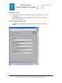
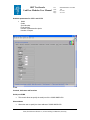
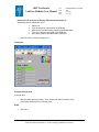
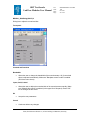
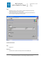
Front panel
Keithley
Controls, indicators and functions
GPIB port (Keithley electrometer for diode mounted at integrating sphere)
•
Allows the user to select the GPIB port of the Keithley electrometer that reads the
photocurrent of the diode mounted at the integrating sphere.
Measurements (Keithley electrometer for diode mounted at integrating sphere)
•
Allows the user to specify the number of measurements for the mean calculation
as well as the standard deviation calculation.
GPIB port (2nd Keithley electrometer)
•
Allows the user to select the GPIB port of the second Keithley (e.g. for test bench
calibration).
ESO, Karl-Schwarzschild-Str. 2, 85748 Garching bei München, Germany
ODT Test-bench:
LabView Modules User Manual
Doc:
Issue:
Date:
Page:
GEN-MAN-ESO-21110-0028
1D2
05.03.08
22 of 135
Measurements (2nd Keithley electrometer)
•
Allows the user to specify the number of measurements for the mean calculation
as well as the standard deviation calculation.
USB port (KE 2100)
•
Allows the user to select the USB port of the KE 2100.
Threshold for room illumination
•
•
Readings that are higher than this threshold [V] are interpreted as: "Room light is
turned on".
Experience shows 2E-1V is an efficient threshold.
Filter wheel
ESO, Karl-Schwarzschild-Str. 2, 85748 Garching bei München, Germany
ODT Test-bench:
LabView Modules User Manual
Doc:
Issue:
Date:
Page:
GEN-MAN-ESO-21110-0028
1D2
05.03.08
23 of 135
Controls, indicators and functions
GPIB port
•
Allows the user to select the GPIB port of the filter wheel controller which is
connected to the filter wheel with the density filters mounted as shown.
Monochromator
ESO, Karl-Schwarzschild-Str. 2, 85748 Garching bei München, Germany
ODT Test-bench:
LabView Modules User Manual
Doc:
Issue:
Date:
Page:
GEN-MAN-ESO-21110-0028
1D2
05.03.08
24 of 135
Controls, indicators and functions
GPIB port
•
The GPIB port of the monochromator MSH 301.
Enable filter table
•
If enabled the order sorting filters are selected automatically depending on the
wavelength (See the table next to this control).
Lines
•
The number of lines of the mounted grating
Offset; Zero; Factor
•
The grating’s parameters (See the user manual of the monochromator MSH 301
for more information).
Wavelength range
•
•
If the user specifies a wavelength (e.g. in the“MSH301_standalone2.0.vi”) out of
range a window appears to indicate that the parameter can not be accepted.
The user is asked to specify a parameter in range.
Bandwidth range
•
•
If the user specifies a bandwidth (e.g. in the“MSH301_standalone2.0.vi”) out of
range a window appears to indicate that the parameter can not be accepted.
The user is asked to specify a parameter in range.
GPIB MONO 1
•
GPIB address of the monochromator with the filter wheels mounted.
GPIB MONO 2
•
GPIB address of the monochromator where the integrating sphere is mounted
ESO, Karl-Schwarzschild-Str. 2, 85748 Garching bei München, Germany
ODT Test-bench:
LabView Modules User Manual
Doc:
Issue:
Date:
Page:
GEN-MAN-ESO-21110-0028
1D2
05.03.08
25 of 135
Lamp (Power Supply)
Control, indicator and function
Serial port
•
Specifies the serial port of the lamp’s power supply.
ESO, Karl-Schwarzschild-Str. 2, 85748 Garching bei München, Germany
ODT Test-bench:
LabView Modules User Manual
Doc:
Issue:
Date:
Page:
GEN-MAN-ESO-21110-0028
1D2
05.03.08
26 of 135
Weather station
Control, indicator and function
Path to "ws_newdata.csv"
•
This file contains the latest readings of the weather station WS 2300. It is created
by the “Data Acquisition Software – V2.93.17”
ESO, Karl-Schwarzschild-Str. 2, 85748 Garching bei München, Germany
ODT Test-bench:
LabView Modules User Manual
Doc:
Issue:
Date:
Page:
GEN-MAN-ESO-21110-0028
1D2
05.03.08
27 of 135
XYZ table
Controls, indicators and functions
GPIB port (ITL 09; ESP 300; MM 4000)
•
•
Allows the user to select the GPIB port from the list.
Press "Refresh" to update the list of available ports.
ESO, Karl-Schwarzschild-Str. 2, 85748 Garching bei München, Germany
ODT Test-bench:
LabView Modules User Manual
Doc:
Issue:
Date:
Page:
GEN-MAN-ESO-21110-0028
1D2
05.03.08
28 of 135
CCD controller - Login
Controls, indicators and functions
Login
•
Allows the user to specify the user name to open the telnet session.
Password
•
Allows the user to specify the password to open the telnet session.
Network address
•
Allows the user to specify the network address to open the telnet session.
Remote port
•
Allows the user to specify the remote port to open the telnet session.
ESO, Karl-Schwarzschild-Str. 2, 85748 Garching bei München, Germany
ODT Test-bench:
LabView Modules User Manual
Doc:
Issue:
Date:
Page:
GEN-MAN-ESO-21110-0028
1D2
05.03.08
29 of 135
CCD controller - CCD
Controls, indicators and functions
CCD name
•
Allows the user to specify the "CCD name" (e.g. “giraffe” or “DMarc”).
CCD parameter
•
•
•
•
•
Allows the user to select between three parameter tables. These are:
“DMarc” ; “tbmite2v” and “New CCD”
Within these three tables the user can specify the CCD's parameters which are
written into the FITS header.
The CCD parameters are selected according to the “CCD name”.
Example 1: CCD name = “tbmite2V”
The table containing the “tbmite2v” parameters is written into the FITS header.
Example 2: CCD name = “giraffe”
The table containing the “New CCD” parameters is written into the FITS header.
ESO, Karl-Schwarzschild-Str. 2, 85748 Garching bei München, Germany
ODT Test-bench:
LabView Modules User Manual
Doc:
Issue:
Date:
Page:
GEN-MAN-ESO-21110-0028
1D2
05.03.08
30 of 135
Available parameters for CCD 1 and CCD 2
•
Model
Grade
Serial Number
Pixel size[um]
Number of photosensitive pixels
Number of outputs
JUMO
Controls, indicators and functions
Serial port JUMO
•
This control allows to specify the serial port of the JUMO IMAGO 500.
Slave address
•
Allows the user to specify the slave address of JUMO IMAGO 500.
ESO, Karl-Schwarzschild-Str. 2, 85748 Garching bei München, Germany
ODT Test-bench:
LabView Modules User Manual
Configuration
Doc:
Issue:
Date:
Page:
GEN-MAN-ESO-21110-0028
1D2
05.03.08
31 of 135
Baud rate; Data bits; Parity; Stop bits
Timeout[ms]
•
This is the number of ms to wait for a response after having
sent a command to JUMO. If the time has elapsed an error
message appears.
Min. response time[ms]
•
This is the delay between send and read.
Temperature CCD1 (Analog input)
•
Allows the user to specify the analog input where the sensor for the temperature
of CCD 1 is connected to.
Temperature CCD2 (Analog input)
•
Allows the user to specify the analog input where the sensor for the temperature
of CCD 2 is connected to.
Pressure (Analog input)
•
Allows the user to specify the analog input where the sensor for the pressure is
connected to.
ESO, Karl-Schwarzschild-Str. 2, 85748 Garching bei München, Germany
ODT Test-bench:
LabView Modules User Manual
Doc:
Issue:
Date:
Page:
GEN-MAN-ESO-21110-0028
1D2
05.03.08
32 of 135
PULPO
Controls, indicators and functions
Temperature CCD1 (Sensor)
•
Allows the user to specify the temperature sensor of CCD 1.
Temperature CCD2 (Sensor)
•
Allows the user to specify the temperature sensor of CCD 2.
ESO, Karl-Schwarzschild-Str. 2, 85748 Garching bei München, Germany
ODT Test-bench:
LabView Modules User Manual
Doc:
Issue:
Date:
Page:
GEN-MAN-ESO-21110-0028
1D2
05.03.08
33 of 135
BOC EDWARDS
Serial port
•
This control allows specifying the serial port of the BOC Edwards vacuum
controller.
SubVI´s
None
Block Diagram
None
ESO, Karl-Schwarzschild-Str. 2, 85748 Garching bei München, Germany
ODT Test-bench:
LabView Modules User Manual
Doc:
Issue:
Date:
Page:
GEN-MAN-ESO-21110-0028
1D2
05.03.08
34 of 135
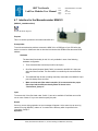
4.3 Interface for the Keithley 6514 Electrometer
(Keythley_6514_standalone2.0.vi)
Icon on the block diagram
Purpose
This VI is used to take current measurements with the Keithley 6514 electrometer.
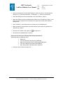
Prerequisites
To avoid communication problems connect the Keithley 6514 to a GPIB port of your PC before
the device is turned on. Make sure that no other device linked to this GPIB bus has the same
GPIB address. (“Measurement & Automation Explorer” >> “Devices & Interfaces” >>”GPIB<bus>”
>> “Scan For Instruments”)
Allow the instrument to warm up at least 2 hours to obtain rated accuracy. (See user manual)
Input
To execute this VI the files listed under “SubVI´s” have to be available. If LabView can not find
one or more of these VI´s you are asked to specify the path.
Output
If an error occurs during operation an error message will appear. At the same time an error log
named “Error log (KE_486) <date>.txt” is created in the directory which is specified in the
“Acquistion_Setup.vi”.
Operation
•
Open the Measurement & Automation Explorer to make sure your PC has detected the
new device (>> “Devices & Interfaces” >>”GPIB<bus>” >> “Scan For Instruments”).
•
Select the GPIB port on the front panel.
•
By selecting “Refresh” new added GPIB ports are detected and added to the list.
•
Specify the number of measurements on the front panel.
•
Press the “Run” button in the upper left (
) to start the acquisition.
ESO, Karl-Schwarzschild-Str. 2, 85748 Garching bei München, Germany
ODT Test-bench:
LabView Modules User Manual
Doc:
Issue:
Date:
Page:
•
The “Busy” button is visible for the duration of the acquisition.
•
The VI stops after having acquired the data.
GEN-MAN-ESO-21110-0028
1D2
05.03.08
35 of 135
How to act if an error occurs directly after having started the VI:
(Most likely there is a GPIB bus error)
•
•
•
•
•
•
Stop the VI.
Turn off all devices connected to the GPIB bus.
Make sure that all devices have differing GPIB addresses.
Turn on the devices connected to the GPIB bus.
Retry the procedure described under “Operation”.
Press the “Run” button again (
) to start a new acquisition.
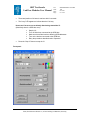
Front panel
Controls and functions
GPIB port
•
Allows the user to select the GPIB port of the KE 6514.
Measurements
•
Allows the user to specify the number of measurements.
ESO, Karl-Schwarzschild-Str. 2, 85748 Garching bei München, Germany
ODT Test-bench:
LabView Modules User Manual
Doc:
Issue:
Date:
Page:
GEN-MAN-ESO-21110-0028
1D2
05.03.08
36 of 135
Indicators
Busy
•
Indicates that the VI is busy.
Mean
•
Displays the mean of the measurements.
Standard deviation
•
Displays the standard deviation.
SubVI´s
Common_error_log2.0(SubVI).vi
Block diagram
Open the “Keythley_6514_standalone2.0.vi” and press “Ctrl” +”E” to view the LabView code
(block diagram).
Known problems
None
References
Model 6514 Programmable Electrometer
www.keithley.de
Contact:
Keithley Instruments GmbH / Germany
Landsberger Strasse 65
P.O. Box 1909
D - 82110 Germering / Germany
Tel: 49-89-8493070
Fax: 49-89-84930787
Email: [email protected]
ESO, Karl-Schwarzschild-Str. 2, 85748 Garching bei München, Germany
ODT Test-bench:
LabView Modules User Manual
Doc:
Issue:
Date:
Page:
GEN-MAN-ESO-21110-0028
1D2
05.03.08
37 of 135
4.4 Interface for the Keithley 486 Picoammeter
(Keythley_486_standalone.vi)
Icon on the block diagram
Purpose
This VI is used to take current measurements using the
Keithley Picoammeter.
Prerequisites
To avoid communication problems connect the Keithley 486 to a GPIB port of your PC before the
device is turned on. Make sure that no other device linked to this GPIB bus has the same GPIB
address. (“Measurement & Automation Explorer” >> “Devices & Interfaces” >>”GPIB<bus>” >>
“Scan For Instruments”)
Allow the instrument to warm up at least 2 hours to obtain rated accuracy. (See user manual)
Input
To execute this VI the files listed under “SubVI´s” have to be available. If LabView can not find
one or more of these VI´s you are asked to specify the path.
Output
If an error occurs during operation an error message will appear. At the same time an error log
named “Error log (KE_486) <date>.txt” is created in the directory which is specified in the
“Acquistion_Setup.vi”.
Operation
•
Open the Measurement & Automation Explorer to make sure your PC has detected the
new device (>> “Devices & Interfaces” >>”GPIB<bus>” >> “Scan For Instruments”).
•
Select the GPIB port on the front panel.
•
By selecting “Refresh” new added GPIB ports are detected and added to the list.
•
Specify the number of measurements to take.
•
Press the “Run” button in the upper left (
•
The “Busy” button is visible for the duration of the acquisition.
•
The VI stops after having acquired the data.
) to start the acquisition.
ESO, Karl-Schwarzschild-Str. 2, 85748 Garching bei München, Germany
ODT Test-bench:
LabView Modules User Manual
Doc:
Issue:
Date:
Page:
GEN-MAN-ESO-21110-0028
1D2
05.03.08
38 of 135
How to act if an error occurs directly after having started the VI:
(Most likely there is a GPIB bus error)
•
•
•
•
•
•
Stop the VI.
Turn off all devices connected to the GPIB bus.
Make sure that all devices have differing GPIB addresses.
Turn on the devices connected to the GPIB bus.
Retry the procedure described under “Operation”.
Press the “Run” button again (
) to start a new acquisition.
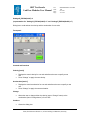
Front panel
Controls and functions
GPIB port
•
Allows the user to select the GPIB port of the KE 486.
Measurements
•
Allows the user to specify the number of measurements.
Indicators
Busy
•
Indicates that the VI is busy.
ESO, Karl-Schwarzschild-Str. 2, 85748 Garching bei München, Germany
ODT Test-bench:
LabView Modules User Manual
Doc:
Issue:
Date:
Page:
GEN-MAN-ESO-21110-0028
1D2
05.03.08
39 of 135
Mean
•
Displays the mean of the measurements.
Standard deviation
•
Displays the standard deviation.
SubVI´s
7 Status.VI
Common_error_log2.0(SubVI).vi
Send Message.vi
Receive Message.vi
Block diagram
Open the “Keythley_486_standalone.vi” and press “Ctrl”+ ”E” to view the LabView code (block
diagram).
Known problems
None
References
www.keithley.de
Contact:
Keithley Instruments GmbH / Germany
Landsberger Strasse 65
P.O. Box 1909
D - 82110 Germering / Germany
Tel: 49-89-8493070
Fax: 49-89-84930787
Web: www.keithley.de
Email: [email protected]
ESO, Karl-Schwarzschild-Str. 2, 85748 Garching bei München, Germany
ODT Test-bench:
LabView Modules User Manual
Doc:
Issue:
Date:
Page:
GEN-MAN-ESO-21110-0028
1D2
05.03.08
40 of 135
4.5 Interface for the Keithley 2100 USB Digital Multimeter
(Keithley 2100 Series Read Single.vi)
Icon on the block diagram
Purpose
This VI is used to measure the voltage or current using the
Keithley 2100 USB Digital Multimeter.
Prerequisites
To avoid communication problems connect the Keithley 2100 to a USB port of your PC before the
device is turned on.
Input
To execute this VI the files listed under “SubVI´s” have to be available. If LabView can not find
one or more of these VI´s you are asked to specify the path.
Output
If an error occurs during operation an error message will appear. At the same time an error log
named “Error log (KE_2100) <date>.txt” is created in the directory which is specified in the
“Acquistion_Setup.vi”.
Operation
•
Select the USB port from the list on the front panel.
•
The port to select should be similar to “USB0::0x05E6::0x2100::1148496::INSTR”.
•
If the USB device is not listed select “Refresh” to refresh the list.
•
Press the “Run” button in the upper left (
•
The “Busy” button is visible for the duration of the acquisition.
•
The VI stops after having acquired the data.
•
Press the “Run” button again (
) to start the acquisition.
) to start a new acquisition.
ESO, Karl-Schwarzschild-Str. 2, 85748 Garching bei München, Germany
ODT Test-bench:
LabView Modules User Manual
Doc:
Issue:
Date:
Page:
GEN-MAN-ESO-21110-0028
1D2
05.03.08
41 of 135
Front panel
Controls and functions
USB port
•
Allows the user to select the USB port of the KE 2100.
Function
•
This control allows the user to select the type of measurement. (DC/AC Volts;
DC/AC Current)
Indicators
Busy
•
Indicates that the VI is busy.
Measurement
•
•
Displays a single measurement.
The unit of the reading is either A (Amp) or V (Volt) depending to the chosen
function.
ESO, Karl-Schwarzschild-Str. 2, 85748 Garching bei München, Germany
ODT Test-bench:
LabView Modules User Manual
Doc:
Issue:
Date:
Page:
GEN-MAN-ESO-21110-0028
1D2
05.03.08
42 of 135
SubVI´s
Keithley 2100 Series.lvlib:Initialize.vi
Common_error_log2.0(SubVI).vi
Keithley 2100 Series.lvlib:Configure Measurement.vi
Keithley 2100 Series.lvlib:Configure DC Volts.vi
Keithley 2100 Series.lvlib:Configure AC Volts.vi
Keithley 2100 Series.lvlib:Configure DC Current.vi
Keithley 2100 Series.lvlib:Configure AC Current.vi
Keithley 2100 Series.lvlib:Configure Trigger.vi
Keithley 2100 Series.lvlib:Action Send Trigger.vi
Keithley 2100 Series.lvlib:Data Read Single.vi
Keithley 2100 Series.lvlib:Close.vi
Block diagram
Open the “Keithley 2100 Series Read Single.vi” and press “Ctrl”+ ”E” to view the LabView code
(block diagram).
Known problems
None
ESO, Karl-Schwarzschild-Str. 2, 85748 Garching bei München, Germany
ODT Test-bench:
LabView Modules User Manual
Doc:
Issue:
Date:
Page:
GEN-MAN-ESO-21110-0028
1D2
05.03.08
43 of 135
References
Model 2100/120 6½-Digit USB Digital Multimeter
www.keithley.de
Contact:
Keithley Instruments GmbH / Germany
Landsberger Strasse 65
P.O. Box 1909
D - 82110 Germering / Germany
Tel: 49-89-8493070
Fax: 49-89-84930787
Email: [email protected]
ESO, Karl-Schwarzschild-Str. 2, 85748 Garching bei München, Germany
ODT Test-bench:
LabView Modules User Manual
Doc:
Issue:
Date:
Page:
GEN-MAN-ESO-21110-0028
1D2
05.03.08
44 of 135
4.6 Interface for the Motorized filter wheel (Newport Model
74041)
(Filter_wheel_standalone.vi)
Icon on the block diagram
Purpose
This VI is used to operate the motorized filter wheel (Newport Model 74041).
Prerequisites
In order to set several densities it is recommended to use the “MSH301_standalone2.0.vi”
because this VI operates both filter wheels in combination and you get the possibility to select
between 29 densities (0 to 4.9).
The third filter wheel with the order sorting filters mounted can also be operated more comfortably
by the “MSH301_standalone2.0.vi”. Nevertheless make sure the filter wheel controller have
different GPIB addresses. (“Measurement & Automation Explorer” >> “Devices & Interfaces”
>>”GPIB<bus>” >> “Scan For Instruments”)
Input
To execute this VI the files listed under “SubVI´s” have to be available. If LabView can not find
one or more of these VI´s you are asked to specify the path.
Output
If an error occurs during operation an error message will appear. At the same time an error log
named “Error log (Filter wheel<serial number>) <date>.txt” is created in the directory which is
specified in the “Acquistion_Setup.vi”.
Operation
•
Open the Measurement & Automation Explorer to make sure your PC has detected the
new device (>> “Devices & Interfaces” >>”GPIB<bus>” >> “Scan For Instruments”).
•
Change the filter wheel position with the hand controller to make sure the filter wheel
works properly.
•
Select the “GPIB port” of the filter wheel controller on the front panel.
•
Press the “Run” button in the upper left (
•
“Filter” button and “Label” indicator of the present filter position will turn into light green.
) to start the VI.
ESO, Karl-Schwarzschild-Str. 2, 85748 Garching bei München, Germany
ODT Test-bench:
LabView Modules User Manual
Doc:
Issue:
Date:
Page:
GEN-MAN-ESO-21110-0028
1D2
05.03.08
45 of 135
How to act if an error occurs directly after having started the VI:
(Most likely there is a GPIB bus error)
•
•
•
•
•
•
Stop the VI.
Turn off all devices connected to the GPIB bus.
Make sure that all devices have differing GPIB addresses.
Turn on the devices connected to the GPIB bus.
Retry the procedure described under “Operation”.
Press the “Stop VI” button to stop the VI.
Front panel
Controls and functions
1; 2; 3; 4; 5; 6
•
Allows to select the filter position. “Filter” button and “Label” indicator of the
present filter position will turn into light green.
STOP
•
Stop this VI.
ESO, Karl-Schwarzschild-Str. 2, 85748 Garching bei München, Germany
ODT Test-bench:
LabView Modules User Manual
Doc:
Issue:
Date:
Page:
GEN-MAN-ESO-21110-0028
1D2
05.03.08
46 of 135
Change label
•
Allows the user to set the label for the filter 1 to 6.
Indicators
Label
•
Displays the label of the filters (if it has one).
SubVI´s
Set Busy.vi
GPIB_read_write(SubVI).vi
Change_label.vi
Unset Busy.vi
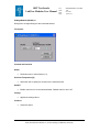
Change_label.vi
Dialog box to change the filter’s labels.
Front panel
ESO, Karl-Schwarzschild-Str. 2, 85748 Garching bei München, Germany
ODT Test-bench:
LabView Modules User Manual
Doc:
Issue:
Date:
Page:
GEN-MAN-ESO-21110-0028
1D2
05.03.08
47 of 135
Controls and functions
Label
•
The new label with max. 8 characters
Filter
•
Pull-down menu to select the filter to rename.
Abort
•
Continue without any changes.
Change
•
Changes the label of the selected filter.
Block diagram
Open the “Filter_wheel_standalone.vi” and press “Ctrl” + ”E” to view the LabView code (block
diagram).
Known problems
None
References
Oriel motorized filter wheel - catalog
Filter wheel controller
Website NEWPORT
Contact:
Herr Jacobs
Newport Spectra-Physics GmbH
Guerickeweg 7
D-64291 Darmstadt
Germany
Tel: +49-(0) 6151-708-923
ESO, Karl-Schwarzschild-Str. 2, 85748 Garching bei München, Germany
ODT Test-bench:
LabView Modules User Manual
Doc:
Issue:
Date:
Page:
GEN-MAN-ESO-21110-0028
1D2
05.03.08
48 of 135
Or
NEWPORT
ORIEL PRODUCT LINE
150 Long Beach Boulevard
Stratford, CT 06615
Phone: (203) 377-8282
(800) 714-5393
Fax:
(203) 378-2457
E-mail: [email protected]
ESO, Karl-Schwarzschild-Str. 2, 85748 Garching bei München, Germany
ODT Test-bench:
LabView Modules User Manual
Doc:
Issue:
Date:
Page:
GEN-MAN-ESO-21110-0028
1D2
05.03.08
49 of 135
4.7 Interface for the Monochromator MSH301
(MSH301_standalone2.0.vi)
Icon on the block diagram
Purpose
This VI is used to operate the monochromator MSH 301.
Prerequisites
To avoid communication problems connect the MSH 301 to a GPIB port of your PC before the
device is turned on. Make sure that no other device linked to this GPIB bus has the same GPIB
address.
Hardware
The described functionality for this VI is only available in case of the following
hardware configuration:
•
Three motorized slits mounted (one slit for each port).
•
One filter wheel (Newport Model 74041) connected to the MSH 301 input port
with color filters mounted. This filter wheel is controlled by the monochromator
itself.
•
Two additional filter wheels (including controller) connected to the MSH 301 input
port with density filters mounted.
•
Make sure that each filter wheel controller (2) is connected to the proper
filter wheel with its different density filters as shown in the
“DeviceDriver_Setup.vi”.
Input
To execute this VI the files listed under “SubVI´s” have to be available. If LabView can not find
one or more of these VI´s you are asked to specify the path.
Output
If an error occurs during operation an error message will appear. At the same time an error log
named “Error log (MSH301) <date>.txt” is created in the directory which is specified in the
“Acquistion_Setup.vi”.
Operation
ESO, Karl-Schwarzschild-Str. 2, 85748 Garching bei München, Germany
ODT Test-bench:
LabView Modules User Manual
Doc:
Issue:
Date:
Page:
GEN-MAN-ESO-21110-0028
1D2
05.03.08
50 of 135
•
Open the Measurement & Automation Explorer to make sure your PC has detected the
new device (>> “Devices & Interfaces” >>”GPIB<bus>” >> “Scan For Instruments”).
•
Select the GPIB port of the monochromator in the “DeviceDriver_Setup.vi”.
•
Select the GPIB port of the two additional filter wheels in the “DeviceDriver_Setup.vi” and
make sure these controllers are connected to the proper filter wheels with its different
density filters.
•
Select “Refresh” in the pull-down menu to refresh the list of available ports.
•
Make sure that the mounted filters (at all filter wheels) are the same as specified in the
“DeviceDriver_Setup.vi”.
•
Press the “Run” button in the upper left (
•
All indicators are updated within 2 seconds.
) to start the VI.
How to act if an error occurs directly after having started the VI:
(Most likely there is a GPIB bus error)
•
•
•
•
•
•
Stop the VI.
Turn off all devices connected to the GPIB bus.
Make sure that all devices have differing GPIB addresses.
Turn on the devices connected to the GPIB bus.
Retry the procedure described under “Operation”.
Press the “Stop VI” button to stop the VI.
ESO, Karl-Schwarzschild-Str. 2, 85748 Garching bei München, Germany
ODT Test-bench:
LabView Modules User Manual
Doc:
Issue:
Date:
Page:
GEN-MAN-ESO-21110-0028
1D2
05.03.08
51 of 135
Front panel
Controls and functions
Calibrate
•
Allows the user to calibrate the monochromator.
Setup
•
Brings up a window to set grating parameters, to rename filters and to adjust
motorized slits (Bandwidth).
ESO, Karl-Schwarzschild-Str. 2, 85748 Garching bei München, Germany
ODT Test-bench:
LabView Modules User Manual
Doc:
Issue:
Date:
Page:
GEN-MAN-ESO-21110-0028
1D2
05.03.08
52 of 135
RW (rewind)
•
Moves the grating fast backwards. (To lower wavelengths).
BS (step backward)
•
•
Moves the grating one step backwards. (To lower wavelengths).
One step is 0.075nm.
Stop
•
Stop motion.
FS (step forward)
•
•
Moves the grating one step forward. (To higher wavelengths).
One step is 0.075 nm.
FF (fast forward)
•
Moves the grating fast forward. (To higher wavelengths).
Destination Wavelength
•
Allows the user to specify the destination wavelength. Press "Goto" to move
monochromator to destination wavelength.
Change
•
Allows the user to select color filters (the upper “Change” button) as well as
density (the lower “Change” button).
Open/Close
•
Allows the user to "OPEN" or "CLOSE" the internal monochromator shutter.
Axial/Lateral
•
Allows the user to select the output port ("Axial" or "Lateral").
Reset
•
Reset all of the monochromator's basic parameters to initialization values. This
action will overwrite LINES, FACTOR, OFFSET, LABELS.
Stop
•
Allows the user to stop this VI (LabView program).
ESO, Karl-Schwarzschild-Str. 2, 85748 Garching bei München, Germany
ODT Test-bench:
LabView Modules User Manual
Doc:
Issue:
Date:
Page:
GEN-MAN-ESO-21110-0028
1D2
05.03.08
53 of 135
Indicators
Present Wavelength
•
Displays the present wavelength of the monochromator.
Color filter
•
Displays the actual filter position of the filter wheel which is operated by the
monochromator. (Color filters mounted)
Filter label
•
Displays the filter label of the color filter which is currently in use.
Density filter
•
Displays the density which results from the filter position of the two further filter
wheels. (Density filters mounted)
Shutter
•
Displays the status of the internal monochromator shutter.
("OPEN" or "CLOSED")
Output port
•
Displays the output port which is currently in use ("Axial" or "Lateral").
SubVI´s
MSH301_ok(SubVI).vi
MSH301_GetWave(SubVI).vi
MSH301_GetShutter(SubVI).vi
MSH301_GetUnits(SubVI).vi
MSH301_Comm(SubVI).vi
ESO, Karl-Schwarzschild-Str. 2, 85748 Garching bei München, Germany
ODT Test-bench:
LabView Modules User Manual
Doc:
Issue:
Date:
Page:
GEN-MAN-ESO-21110-0028
1D2
05.03.08
54 of 135
MSH301_GetPort(SubVI).vi
MSH301_GetFilter2.0(SubVI).vi
MSH301_GetFrLabel(SubVI).vi
DeviceDriver_Setup.vi
Filter_wheel_remotecontrol.vi
FilterPosition to Density.vi
Common_error_log2.0(SubVI).vi
MSH301_MoveSteps(SubVI).vi
Check range(SubVI).vi
MSH301_GoWave(SubVI).vi
MSH301_FilterDialog(SubVI).vi
MSH301_SetShutter(SubVI).vi
MSH301_SetupStandalone(SubVI).vi
MSH301_Callibration(SubVI).vi
MSH301_SetPort(SubVI).vi
MSH301_SendCommand(SubVI).vi
ESO, Karl-Schwarzschild-Str. 2, 85748 Garching bei München, Germany
ODT Test-bench:
LabView Modules User Manual
Doc:
Issue:
Date:
Page:
GEN-MAN-ESO-21110-0028
1D2
05.03.08
55 of 135
MSH301_Callibration(SubVI).vi
Dialog box for calibrating the monochromator
Front panel
Controls and functions
Ok
•
Replaces the "Present wavelength" with the "Calibration wavelength".
Cancel
•
Continues without any changes.
Calibration Wavelength
•
The new wavelength.
Indicators
Present Wavelength
•
Displays the present wavelength.
Present Grating
•
This is the ID number of the chosen grating. It is possible to mount up to three
gratings.
ESO, Karl-Schwarzschild-Str. 2, 85748 Garching bei München, Germany
ODT Test-bench:
LabView Modules User Manual
Doc:
Issue:
Date:
Page:
GEN-MAN-ESO-21110-0028
1D2
05.03.08
56 of 135
Present grating's Lines/mm
•
Displays the number of lines/mm of the mounted grating.
MSH301_SetupStandalone(SubVI).vi
Dialog box for setting the monochromator’s parameters as well as the filter’s labels.
Front panel
Controls and functions
Ok
•
•
Changes filter label as well as grating parameters "Lines/mm", "Factor", "Offset",
"Zero" and "Label".
WARNING: Changing the calibration parameter will affect monochromator
accuracy.
ESO, Karl-Schwarzschild-Str. 2, 85748 Garching bei München, Germany
ODT Test-bench:
LabView Modules User Manual
Doc:
Issue:
Date:
Page:
GEN-MAN-ESO-21110-0028
1D2
05.03.08
57 of 135
Cancel
•
Continue without any changes.
Lines/mm; Factor; Offset; Zero
•
Please refer to the Manual concerning these parameters.
Label
•
The label of grating 1.
Position
•
Allows the user to select a filter to rename.
Motorized Slits
•
Brings up a window to adjust the motorized slits (Bandwidth)
Reinitialize to calibration parameters (default)
•
Pressing "Ok" with this control enabled reinitializes the monochromator to its
default parameters for grating 1. The calibration parameters are specified in the
"DeviceDriver_Setup.vi".
Label (max.8 characters)
•
Allows the user to rename the selected filter (Color filters mounted).
The number of characters must not exceed eight characters.
ESO, Karl-Schwarzschild-Str. 2, 85748 Garching bei München, Germany
ODT Test-bench:
LabView Modules User Manual
Doc:
Issue:
Date:
Page:
GEN-MAN-ESO-21110-0028
1D2
05.03.08
58 of 135
MSH301_SlitsDialog(SubVI).vi
Dialog box to adjust the motorized slits.
Front panel
Controls and functions
Bandwidth
•
Allows the user to change the bandwidth of the monochromator. All (3) motorized
slits are adjusted automatically. Make sure "Bandpass control" mode is enabled.
(Pull-down menu above)
Inport; Axial; Lateral
•
Allows the user to adjust the motorized slits of the monochromator maually. Make
sure "Manual slits control" is enabled (in the upper left of this panel). Press "OK"
for the changes to take effect.
•
Accept the new parameters.
Ok
Cancel
•
Continues without any changes.
ESO, Karl-Schwarzschild-Str. 2, 85748 Garching bei München, Germany
ODT Test-bench:
LabView Modules User Manual
Doc:
Issue:
Date:
Page:
GEN-MAN-ESO-21110-0028
1D2
05.03.08
59 of 135
Mode control
•
•
Select "Bandpass control" to adjust the bandwidth.
Select "Manual slits control" to adjust the slits manually.
Block diagram
Open the “MSH301_standalone2.0.vi” and press “Ctrl”+ ”E” to view the LabView code (block
diagram).
Known problems
None
References
Data sheet MSH 301
Website
Contact:
Germany:
Guerickeweg 7
D-64291 Darmstadt
Tel: +49-(0) 6151-708-0
Fax: +49-(0) 6151-708-952
E-mail: Newport Spectra-Physics GmbH
Jochen Mentges
Phone: +49/6151/8806 35
Email: [email protected]
ESO, Karl-Schwarzschild-Str. 2, 85748 Garching bei München, Germany
ODT Test-bench:
LabView Modules User Manual
Doc:
Issue:
Date:
Page:
GEN-MAN-ESO-21110-0028
1D2
05.03.08
60 of 135
4.8 Interface for the Newport Power Supply (Model 69931)
(PowerSupply_standalone.vi)
Icon on the block diagram
Purpose
This VI is used to operate the Newport Power Supply (Model 69931).
Prerequisites
To avoid communication problems connect the Newport Power Supply to a serial port of your PC
before the device is turned on. It is strongly recommended not to use this VI during an automated
data acquisition at the test bench in 051.
Do not use this VI if one of the following VI´s is running:
•
•
•
“MasterPanel2.0.vi”
“FIERA_standalone.vi”
“LabViewPrism_New testbench.vi”
Hardware
The described functionality for this VI is only available in case of the following
hardware configuration:
•
The 300W Radiometric Power Supply (Model 69931) is connected to a Newport
Series Q Lamp Housing (Model 60090) and the appropriate lamp model.
(See User Manual for 300W Radiometric Power Supply (Model 69931))
Input
To execute this VI the files listed under “SubVI´s” have to be available. If LabView can not find
one or more of these VI´s you are asked to specify the path.
Output
If an error occurs during operation an error message will appear. At the same time an error log
named “Error log (Power Supply) <date>.txt” is created in the directory which is specified in the
“Acquistion_Setup.vi”.
ESO, Karl-Schwarzschild-Str. 2, 85748 Garching bei München, Germany
ODT Test-bench:
LabView Modules User Manual
Doc:
Issue:
Date:
Page:
GEN-MAN-ESO-21110-0028
1D2
05.03.08
61 of 135
Operation
•
Open the Measurement & Automation Explorer to make sure your PC has detected the
new device (>> “Devices & Interfaces” >>”GPIB<bus>” >> “Scan For Instruments”).
•
Select the serial port on the front panel. Select “Refresh” to update the list of available
ports.
•
Press the “Run” button in the upper left (
•
All indicators are updated within 5 seconds.
•
Press the “Stop VI” button to stop the VI.
) to start the VI.
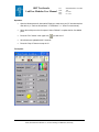
Front panel
ESO, Karl-Schwarzschild-Str. 2, 85748 Garching bei München, Germany
ODT Test-bench:
LabView Modules User Manual
Doc:
Issue:
Date:
Page:
GEN-MAN-ESO-21110-0028
1D2
05.03.08
62 of 135
Controls and functions
Serial port
•
Allows the user to select the serial port of the lamp’s power supply.
Change
•
Allows the user to switch between the two modes (constant current/constant
power).
Set level
•
•
•
Opens a further panel to set the current/power level.
If the lamp is started (“Start lamp” button) a gradual ramp-up to the preset current
or power level begins.
Press the "Change" button above to change the mode (constant current/
constant power -mode).
Reset
•
Resets the “Lamp hours” display
Start lamp
•
•
•
This button begins a gradual ramp-up to the preset current or power level (Press
the "Set level" button to change these parameters).
The ramp-up time is approximately 15 seconds.
The lamp needs to warm up about 1 hour to work properly.
Stop lamp
•
This button begins a gradual ramp-down from the preset current or power level to
0 (AMPS or WATTS). The ramp-down time is approximately 15 seconds.
Stop VI
•
Stops the VI
Time Target [ every]
•
Specifies how much time must elapse before all indicators are updated.
(Therefore enable the control “Update” on the left)
Update
•
If enabled the indicators are updated at regular intervals.
ESO, Karl-Schwarzschild-Str. 2, 85748 Garching bei München, Germany
ODT Test-bench:
LabView Modules User Manual
Doc:
Issue:
Date:
Page:
GEN-MAN-ESO-21110-0028
1D2
05.03.08
63 of 135
Indicators
Busy
•
Indicates that the VI is busy.
Mode
•
•
•
•
Indicates the present mode.
Mode 1 is "Current mode" (constant current)
Mode 2 is "Power mode" (constant power)
Press the "Change" button next to this indicator to change MODE.
Current
•
Displays the current [AMPS].
Voltage
•
Displays the voltage [VOLTS].
Power
•
Displays the power [WATTS].
Lamp hours
•
•
Indicates the number of hours since the last reset.
Press the "RESET" button on the right to reset this indicator (to 0 hrs.).
Lamp on?
•
•
Indicates if the lamp is turned on ("yellow"), or turned off ("black").
Lamp should warm up at least 1 hour before operation.
SubVI´s
DeviceDriver_Setup.vi
Common_error_log2.0(SubVI).vi
VISA_serial(SubVI).vi
ESO, Karl-Schwarzschild-Str. 2, 85748 Garching bei München, Germany
ODT Test-bench:
LabView Modules User Manual
Doc:
Issue:
Date:
Page:
GEN-MAN-ESO-21110-0028
1D2
05.03.08
64 of 135
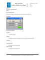
Set_current&power.vi
Set_current&power.vi
Dialog box to display or change the power level as well as the current level.
Front panel
Controls and functions
Continue
•
Closes the window.
Change
•
Changes the present level (power level / current level) to the specified value.
Indicators
Current level [A]
•
Displays the present current level.
Power level [W]
•
Displays the present power level.
ESO, Karl-Schwarzschild-Str. 2, 85748 Garching bei München, Germany
ODT Test-bench:
LabView Modules User Manual
Doc:
Issue:
Date:
Page:
GEN-MAN-ESO-21110-0028
1D2
05.03.08
65 of 135
Block diagram
Open the “PowerSupply_standalone.vi” and press “Ctrl”+ ”E” to view the LabView code (block
diagram).
Known problems
None
References
Product Description
Website NEWPORT
Contact:
NEWPORT
ORIEL PRODUCT LINE
150 Long Beach Boulevard
Statford, CT 06615
Phone: (203) 377-8282
(800) 714-5393
Fax:
(203) 378-2457
E-mail: [email protected]
Germany:
Guerickeweg 7
D-64291 Darmstadt
Tel: +49-(0) 6151-708-0
Fax: +49-(0) 6151-708-952
E-mail: Newport Spectra-Physics GmbH
ESO, Karl-Schwarzschild-Str. 2, 85748 Garching bei München, Germany
ODT Test-bench:
LabView Modules User Manual
Doc:
Issue:
Date:
Page:
GEN-MAN-ESO-21110-0028
1D2
05.03.08
66 of 135
4.9 Interface for the Newport ESP 300 Motion Controller
(ESP300_standalone.vi)
Icon on the block diagram
Purpose
This VI is used to operate the Newport ESP 300.
Prerequisites
To avoid communication problems connect the ESP 300 to a GPIB port of your PC before the
device is turned on. Make sure that no other device linked to this GPIB bus has the same GPIB
address (“Measurement & Automation Explorer” >> “Devices & Interfaces” >>”GPIB<bus>” >>
“Scan For Instruments”).
Hardware
The described functionality for this VI is only available in case of the following
hardware configuration:
•
3 axes connected to the motion controller.
Input
To execute this VI the files listed under “SubVI´s” have to be available. If LabView can not find
one or more of these VI´s you are asked to specify the path.
Output
If an error occurs during operation an error message will appear. At the same time an error log
named “Error log (ESP 300) <date>.txt” is created in the directory which is specified in the
“Acquistion_Setup.vi”.
Operation
•
Open the Measurement & Automation Explorer to make sure your PC has detected the
new device (>> “Devices & Interfaces” >>”GPIB<bus>” >> “Scan For Instruments”)
•
Select the GPIB port of the ESP 300 Motion Controller on the front panel of the VI.
•
Select “Refresh” to refresh the list of available ports.
•
Press the “Run” button in the upper left (
) to start the VI.
ESO, Karl-Schwarzschild-Str. 2, 85748 Garching bei München, Germany
ODT Test-bench:
LabView Modules User Manual
Doc:
Issue:
Date:
Page:
•
The actual position of all axes is read out within 3 seconds.
•
The “busy” LED appears to indicate that the VI is busy.
GEN-MAN-ESO-21110-0028
1D2
05.03.08
67 of 135
How to act if an error occurs directly after having started the VI:
(Most likely there is a GPIB bus error)
•
•
•
•
•
•
Stop the VI.
Turn off all devices connected to the GPIB bus.
Make sure that all devices have differing GPIB addresses.
Turn on the devices connected to the GPIB bus.
Retry the procedure described under “Operation”.
Press the “Stop VI” button to stop the VI.
Front panel
ESO, Karl-Schwarzschild-Str. 2, 85748 Garching bei München, Germany
ODT Test-bench:
LabView Modules User Manual
Doc:
Issue:
Date:
Page:
GEN-MAN-ESO-21110-0028
1D2
05.03.08
68 of 135
Controls and functions
GPIB port
•
Allows the user to select the GPIB port from the list.
Increment [mm]
•
•
Allows the user to set the incremental step. Press the "+" button to step forward.
Press the "-" button to step backward.
New position= <Actual pos> +/- <Increment>.
Absolute pos[mm]
•
Allows the user to specify the absolute position. Press "goto" to move the slide to
the absolute position.
•
•
Press this button to step forward (once or continuously).
New position= <Actual pos> + <Increment>.
•
•
Press this button to step backward (once or continuously).
New position= <Actual pos> - <Increment>.
+
-
goto
•
Moves the slit to the absolute position specified under "Absolute pos".
Settings
•
Allows the user to read and set the velocity as well as the acceleration for this
axis.
Check Position
•
Allows the user to read the actual position of all 3 axes.
Define home
•
The actual position off all three axes is set to "0".
Search for home
•
Move all axes to position "0".
ESO, Karl-Schwarzschild-Str. 2, 85748 Garching bei München, Germany
ODT Test-bench:
LabView Modules User Manual
Doc:
Issue:
Date:
Page:
GEN-MAN-ESO-21110-0028
1D2
05.03.08
69 of 135
Abort motion
•
Stops all motion.
Stop VI
•
Stops the VI.
Indicators
Busy
•
Appears when the VI is in busy state.
Actual pos[mm]
•
Indicates the actual slide position of this axis.
SubVI´s
esp_gpib_comm_ASCII.vi
esp_gpib_init_system.vi
Common_error_log2.0(SubVI).vi
SettingsX_ESP300(SubVI).vi
SettingsY_ESP300(SubVI).vi
SettingsZ_ESP300(SubVI).vi
ESO, Karl-Schwarzschild-Str. 2, 85748 Garching bei München, Germany
ODT Test-bench:
LabView Modules User Manual
Doc:
Issue:
Date:
Page:
GEN-MAN-ESO-21110-0028
1D2
05.03.08
70 of 135
SettingsX_ESP300(SubVI).vi
(representative for “SettingsY_ESP300(SubVI).vi” and “SettingsZ_ESP300(SubVI).vi”)
Dialog box to read and set the velocity and the acceleration for one axis.
Front panel
Controls and functions
Velocity [mm/s]
•
•
Displays the actual velocity for one axis and allows the user to specify a new
one.
Press “Change” to apply the new velocity.
Acceleration [mm/s²]
•
•
Displays the actual acceleration for one axis and allows the user to specify a new
one.
Press “Change” to apply the new acceleration.
Change
•
Allows the user to change either the velocity (upper “Change” button) or the
acceleration (lower “Change button”) for one axis.
Continue
•
Closes the dialog box.
ESO, Karl-Schwarzschild-Str. 2, 85748 Garching bei München, Germany
ODT Test-bench:
LabView Modules User Manual
Doc:
Issue:
Date:
Page:
GEN-MAN-ESO-21110-0028
1D2
05.03.08
71 of 135
Indicators
Velocity [mm/s]
•
•
Displays the actual velocity for one axis and allows the user to specify a new
one.
Press “Change” to apply the new velocity.
Acceleration [mm/s²]
•
•
Displays the actual acceleration for one axis and allows the user to specify a new
one.
Press “Change” to apply the new acceleration.
Block Diagram
Open the “ESP300_standalone.vi” and press “Ctrl” +”E” to view the LabView code (block
diagram).
Known problems
None
References
ESP300 3 Axis Motion Controller/Driver
Website NEWPORT
Contact:
Guerickeweg 7
D-64291 Darmstadt
Germany
Tel: +49-(0) 6151-708-0
Fax: +49-(0) 6151-708-952
E-mail: Newport Spectra-Physics GmbH
ESO, Karl-Schwarzschild-Str. 2, 85748 Garching bei München, Germany
ODT Test-bench:
LabView Modules User Manual
Doc:
Issue:
Date:
Page:
GEN-MAN-ESO-21110-0028
1D2
05.03.08
72 of 135
4.10 Interface for the Newport ITL 09 Motion Controller
(ESP300_standalone.vi)
Icon on the block diagram
Purpose
This VI is used to operate the Newport ITL 09.
Prerequisites
To avoid communication problems connect the ITL 09 to a GPIB port of your PC before the
device is turned on. Make sure that no other device linked to this GPIB bus has the same GPIB
address. (“Measurement & Automation Explorer” >> “Devices & Interfaces” >>”GPIB<bus>” >>
“Scan For Instruments”)
Hardware
The described functionality for this VI is only available in case of the following
hardware configuration:
•
2 axes connected to the motion controller.
Input
To execute this VI the files listed under “SubVI´s” have to be available. If LabView can not find
one or more of these VI´s you are asked to specify the path.
Output
If an error occurs during operation an error message will appear. At the same time an error log
named “Error log (ITL 09) <date>.txt” is created in the directory which is specified in the
“Acquistion_Setup.vi”.
Operation
•
Open the Measurement & Automation Explorer to make sure your PC has detected the
new device (>> “Devices & Interfaces” >>”GPIB<bus>” >> “Scan For Instruments”).
•
Select the GPIB port of the ITL 09 Motion Controller on the front panel of the VI.
•
Select “Refresh” to refresh the list of available ports.
ESO, Karl-Schwarzschild-Str. 2, 85748 Garching bei München, Germany
ODT Test-bench:
LabView Modules User Manual
Doc:
Issue:
Date:
Page:
•
Press the “Run” button in the upper left (
•
The actual position of all axes is read within 3 seconds.
•
The “busy” LED appears to indicate that the VI is busy.
GEN-MAN-ESO-21110-0028
1D2
05.03.08
73 of 135
) to start the VI.
How to act if an error occurs directly after having started the VI:
(Most likely there is a GPIB bus error)
•
•
•
•
•
•
Stop the VI.
Turn off all devices connected to the GPIB bus.
Make sure that all devices have differing GPIB addresses.
Turn on the devices connected to the GPIB bus.
Retry the procedure described under “Operation”.
Press the “Stop VI” button to stop the VI.
Front panel
ESO, Karl-Schwarzschild-Str. 2, 85748 Garching bei München, Germany
ODT Test-bench:
LabView Modules User Manual
Doc:
Issue:
Date:
Page:
GEN-MAN-ESO-21110-0028
1D2
05.03.08
74 of 135
Controls and functions
GPIB port
•
Allows the user to select the GPIB port from the list.
Increment [mm]
•
•
Allows the user to set the incremental step. Press the "+" button to step forward.
Press the "-" button to step backward.
New position= <Actual pos> +/- <Increment>.
Absolute pos[mm]
•
Allows the user to specify the absolute position. Press "goto" to move the slide to
the absolute position.
•
•
Press this button to step forward (once or continuously).
New position= <Actual pos> + <Increment>.
•
•
Press this button to step backward (once or continuously).
New position= <Actual pos> - <Increment>.
+
-
goto
•
Moves the slit to the absolute position specified under "Absolute pos".
Settings
•
Allows the user to read and set the velocity as well as the acceleration for this
axis.
Check Position
•
Allows the user to read the actual position of the two axes.
Define home
•
The actual position off all three axes is set to "0".
Search for home
•
Move all axes to position "0".
ESO, Karl-Schwarzschild-Str. 2, 85748 Garching bei München, Germany
ODT Test-bench:
LabView Modules User Manual
Doc:
Issue:
Date:
Page:
GEN-MAN-ESO-21110-0028
1D2
05.03.08
75 of 135
Abort motion
•
Stops all motion.
Stop VI
•
Stops the VI.
Indicators
Busy
•
Appears when the VI is busy.
Actual pos[mm]
•
Indicates the actual slide position of this axis.
SubVI´s
ITL09_GPIB_communication (SubVI).vi
esp_gpib_init_system.vi
Common_error_log2.0(SubVI).vi
ITL09_XSettings(SubVI).vi
ITL09_YSettings(SubVI).vi
ESO, Karl-Schwarzschild-Str. 2, 85748 Garching bei München, Germany
ODT Test-bench:
LabView Modules User Manual
Doc:
Issue:
Date:
Page:
GEN-MAN-ESO-21110-0028
1D2
05.03.08
76 of 135
ITL09_XSettings(SubVI).vi
(representative for “ITL09_YSettings(SubVI).vi”)
Dialog box to read and set the velocity for one axis.
Front panel
Controls and functions
Velocity [mm/s]
•
•
Displays the actual velocity for one axis and allows the user to specify a new
one.
Press “Change” to apply the new velocity.
Change
•
Allows the user to change the current velocity settings.
Continue
•
Closes the dialog box.
Indicators
Velocity [mm/s]
•
•
Displays the actual velocity for one axis and allows the user to specify a new
one.
Press “Change” to apply the new velocity.
ESO, Karl-Schwarzschild-Str. 2, 85748 Garching bei München, Germany
ODT Test-bench:
LabView Modules User Manual
Doc:
Issue:
Date:
Page:
GEN-MAN-ESO-21110-0028
1D2
05.03.08
77 of 135
Block diagram
Open the “ITL 09_standalone.vi” and press “Ctrl” +”E” to view the LabView code (block diagram).
Known problems
After having connected the Newport ITL09 to the GPIB bus the first time an error occurs when the
VI is started. In this case start the VI a second time.
References
Website NEWPORT
Contact:
Guerickeweg 7
D-64291 Darmstadt
Germany
Tel: +49-(0) 6151-708-0
Fax: +49-(0) 6151-708-952
E-mail: Newport Spectra-Physics GmbH
ESO, Karl-Schwarzschild-Str. 2, 85748 Garching bei München, Germany
ODT Test-bench:
LabView Modules User Manual
Doc:
Issue:
Date:
Page:
GEN-MAN-ESO-21110-0028
1D2
05.03.08
78 of 135
4.11 Interface for the Newport MM 4000 Motion Controller
(MM4000_standalone.vi)
Icon on the block diagram
Purpose
This VI is used to operate the Newport MM 4000.
Prerequisites
To avoid communication problems connect the MM 4000 to a GPIB port of your PC before the
device is turned on. Make sure that no other device linked to this GPIB bus has the same GPIB
address. (“Measurement & Automation Explorer” >> “Devices & Interfaces” >>”GPIB<bus>” >>
“Scan For Instruments”)
Hardware
The described functionality for this VI is only available in case of the following
hardware configuration:
•
3 axes connected to the motion controller.
Input
To execute this VI the files listed under “SubVI´s” have to be available. If LabView can not find
one or more of these VI´s you are asked to specify the path.
Output
If an error occurs during operation an error message will appear. At the same time an error log
named “Error log (MM 4000) <date>.txt” is created in the directory which is specified in the
“Acquistion_Setup.vi”.
Operation
•
Open the Measurement & Automation Explorer to make sure your PC has detected the
new device (>> “Devices & Interfaces” >>”GPIB<bus>” >> “Scan For Instruments”).
•
Select the GPIB port of the MM 4000 Motion Controller on the front panel of the VI.
•
Select “Refresh” to refresh the list of available ports.
ESO, Karl-Schwarzschild-Str. 2, 85748 Garching bei München, Germany
ODT Test-bench:
LabView Modules User Manual
Doc:
Issue:
Date:
Page:
•
Press the “Run” button in the upper left (
•
The actual position of all axes is read out within 3 seconds.
•
The “busy” LED appears to indicate that the VI is busy.
GEN-MAN-ESO-21110-0028
1D2
05.03.08
79 of 135
) to start the VI.
How to act if an error occurs directly after having started the VI:
(Most likely there is a GPIB bus error)
•
•
•
•
•
•
Stop the VI.
Turn off all devices connected to the GPIB bus.
Make sure that all devices have differing GPIB addresses.
Turn on the devices connected to the GPIB bus.
Retry the procedure described under “Operation”.
Press the “Stop VI” button to stop the VI.
Front panel
ESO, Karl-Schwarzschild-Str. 2, 85748 Garching bei München, Germany
ODT Test-bench:
LabView Modules User Manual
Doc:
Issue:
Date:
Page:
GEN-MAN-ESO-21110-0028
1D2
05.03.08
80 of 135
Controls and functions
GPIB port
•
Allows the user to select the GPIB port from the list.
Increment [mm]
•
•
Allows the user to set the incremental step. Press the "+" button to step forward.
Press the "-" button to step backward.
New position= <Actual pos> +/- <Increment>.
Absolute pos[mm]
•
Allows the user to specify the absolute position. Press "goto" to move the slide to
the absolute position.
•
•
Press this button to step forward (once or continuously).
New position= <Actual pos> + <Increment>.
•
•
Press this button to step backward (once or continuously).
New position= <Actual pos> - <Increment>.
+
-
goto
•
Moves the slit to the absolute position specified under "Absolute pos".
Settings
•
Allows the user to read and set the velocity as well as the acceleration for this
axis.
Check Position
•
Allows the user to read the actual position of all 3 axes.
Define home
•
The actual position off all three axes is set to "0".
Search for home
•
Move all axes to position "0".
ESO, Karl-Schwarzschild-Str. 2, 85748 Garching bei München, Germany
ODT Test-bench:
LabView Modules User Manual
Doc:
Issue:
Date:
Page:
GEN-MAN-ESO-21110-0028
1D2
05.03.08
81 of 135
Abort motion
•
Stops all motion.
Stop VI
•
Stops the VI.
Indicators
Busy
•
Appears when the VI is in busy state.
Actual pos[mm]
•
Indicates the actual slide position of this axis.
SubVI´s
esp_gpib_comm_ASCII.vi
esp_gpib_init_system.vi
Common_error_log2.0(SubVI).vi
SettingsX(SubVI).vi
SettingsY(SubVI).vi
SettingsZ(SubVI).vi
ESO, Karl-Schwarzschild-Str. 2, 85748 Garching bei München, Germany
ODT Test-bench:
LabView Modules User Manual
Doc:
Issue:
Date:
Page:
GEN-MAN-ESO-21110-0028
1D2
05.03.08
82 of 135
SettingsX(SubVI).vi
(representative for “SettingsY(SubVI).vi and SettingsZ(SubVI).vi”)
Dialog box to read and set the velocity and the acceleration for one axis.
Front panel
Controls and functions
Velocity [mm/s]
•
•
Displays the actual velocity for one axis and allows the user to specify a new
one.
Press “Change” to apply the new velocity.
Acceleration [mm/s²]
•
•
Displays the actual acceleration for one axis and allows the user to specify a new
one.
Press “Change” to apply the new acceleration.
Change
•
Changes either velocity (upper “Change” button) or acceleration (lower “Change
button”) for one axis.
Continue
•
Closes the dialog box.
ESO, Karl-Schwarzschild-Str. 2, 85748 Garching bei München, Germany
ODT Test-bench:
LabView Modules User Manual
Doc:
Issue:
Date:
Page:
GEN-MAN-ESO-21110-0028
1D2
05.03.08
83 of 135
Indicators
Velocity [mm/s]
•
•
Displays the actual velocity for one axis and allows the user to specify a new
one.
Press “Change” to apply the new velocity.
Acceleration [mm/s²]
•
•
Displays the actual acceleration for one axis and allows the user to specify a new
one.
Press “Change” to apply the new acceleration.
Block Diagram
Open the “MM4000_standalone.vi” and press “Ctrl” +”E” to view the LabView code (block
diagram).
Known problems
None
References
Website NEWPORT
Contact:
Guerickeweg 7
D-64291 Darmstadt
Germany
Tel: +49-(0) 6151-708-0
Fax: +49-(0) 6151-708-952
E-mail: Newport Spectra-Physics GmbH
ESO, Karl-Schwarzschild-Str. 2, 85748 Garching bei München, Germany
ODT Test-bench:
LabView Modules User Manual
Doc:
Issue:
Date:
Page:
GEN-MAN-ESO-21110-0028
1D2
05.03.08
84 of 135
4.12 Interface for FIERA
(FIERA_standalone.vi)
Icon on the block diagram
Purpose
This VI is used to operate FIERA in order to take, save and
display single exposures.
Prerequisites
It is strongly recommended not to use this VI during an automated data acquisition at the test
bench in 051. Make sure the FIERA system you intend to use is not used by another person or
program.
Do not run this VI if one of the following VI´s is executed:
•
•
“MasterPanel2.0.vi”
“LabViewPrism_New testbench.vi”
Hardware
The described functionality for this VI is only available in case of the following
hardware configuration:
•
The shutter type you intend to use is connected to PULPO. Connect the USB
interface board to PULPO in order to use the internal monochromator shutter.
•
FIERA has to be turned on.
•
PULPO is connected to FIERA.
•
Keithley electrometer (KE 2100 and KE 6514), Monochromator MSH 301 and the
two filter wheel controller connected to the GPIB ports which are specified in the
“DeviceDriver_Setup.vi”.
Input
To execute this VI the files listed under “SubVI´s” have to be available. If LabView can not find
one or more of these VI´s you are asked to specify the path.
ESO, Karl-Schwarzschild-Str. 2, 85748 Garching bei München, Germany
ODT Test-bench:
LabView Modules User Manual
Doc:
Issue:
Date:
Page:
GEN-MAN-ESO-21110-0028
1D2
05.03.08
85 of 135
Verify the following input parameters and save changes by default before the VI is started:
“DeviceDriver_Setup.vi”:
•
“CCD controller”
if you decided to write additional comments into the FITS header:
•
•
•
•
•
•
“Keithley”
“Filter wheel”
“Monochromator”
“Lamp (Power Supply)”
“Weather station”
“PULPO”
“Acquistion_Setup.vi”
•
•
•
•
•
•
“At the beginning of an acquisition”
>> “Clear directory on odta<X> before an exposure is taken (strongly
recommended)”
>> ”Send a complete setup to the FIERA software before an exposure is
taken (recommended).”
“During acquisition” >> “Action if exposure fails”
“Miscellaneous”
“FITS header”
“Files”
“Shutter”
In order to save changes right click on the control and select:
Data Operations >> Make Current Value Default
Afterwards save the whole setup as follows:
File >> Save (or press “CTRL” + “S”)
Output
If an exposure is taken the following files are created in the directory which is specified in the
“Acquistion_Setup.vi” (“Files” >> “Relative path to manual CCD exposures”). :
•
•
<file name>.fits
<file name>.fits.det
if you decided to write the FITS header into a text file:
•
<file name>_HDU.txt
ESO, Karl-Schwarzschild-Str. 2, 85748 Garching bei München, Germany
ODT Test-bench:
LabView Modules User Manual
Doc:
Issue:
Date:
Page:
GEN-MAN-ESO-21110-0028
1D2
05.03.08
86 of 135
if an error occurs:
•
Error log (FIERA) <date>.txt
Operation
•
Press the “Run” button in the upper left (
•
The “busy” LED appears to indicate that the VI is busy. In busy state you won’t be able
to press any button.
•
The telnet session to the remote location (see “Input” ) is opened.
•
The “opState” (operational state) is read out. Make sure the “opState” is “online” in order
to take exposures.
•
Otherwise use the controls to put FIERA online.
(See “Controls and functions” for a detailed description)
•
Determine parameters for the exposure(s) (Exposure time, Type …).
•
Press “Start exposure” to take the exposure(s) with the specified parameters.
•
Press the “Stop VI” button to stop the VI.
) to start the VI.
ESO, Karl-Schwarzschild-Str. 2, 85748 Garching bei München, Germany
ODT Test-bench:
LabView Modules User Manual
Doc:
Issue:
Date:
Page:
GEN-MAN-ESO-21110-0028
1D2
05.03.08
87 of 135
Front panel
Setup
ESO, Karl-Schwarzschild-Str. 2, 85748 Garching bei München, Germany
ODT Test-bench:
LabView Modules User Manual
Doc:
Issue:
Date:
Page:
GEN-MAN-ESO-21110-0028
1D2
05.03.08
88 of 135
Indicators
ESO, Karl-Schwarzschild-Str. 2, 85748 Garching bei München, Germany
ODT Test-bench:
LabView Modules User Manual
Doc:
Issue:
Date:
Page:
GEN-MAN-ESO-21110-0028
1D2
05.03.08
89 of 135
Controls and functions
Busy
•
Indicates that the program is busy.
Type
•
•
Allows the user to specify the exposure type.
Available exposure types are: Normal; Dark; TDI (Time Delayed Integration)
TDI delay [ms]
•
If you select "TDI" for the exposure type this is the delay between the command
to start the exposure and the open shutter command.
Exposure time [s]
•
Allows the user to specify the exposure time (integration time).
Readout mode
•
Allows the user to select the available readout modes for the specified CCD
name.
Number of exposures
•
The number of exposures to take.
Delay [s]
•
If you intend to take more than one exposure, this defines the delay between
them.
Save file as
•
•
•
If enabled the file is going to be saved in the directory which is specified in the
"Acquisition_Setup.vi" (“Files” >> "Relative path to manual CCD exposures").
Allows the user to specify the name of the FITS file(s). If more than one exposure
is taken the files are numbered.
A file name mustn’t contain any of the following characters: / . \ : " ? | < >
Display Image
•
Allows the user to display the previously taken image.
Display Table
•
Allows you to display the FITS table of the previously taken image.
ESO, Karl-Schwarzschild-Str. 2, 85748 Garching bei München, Germany
ODT Test-bench:
LabView Modules User Manual
Doc:
Issue:
Date:
Page:
GEN-MAN-ESO-21110-0028
1D2
05.03.08
90 of 135
Start FIERA
•
Starts the FIERA software from the instrument workstation.
Put FIERA online
•
Puts the FIERA software online.
Start exposure
•
Starts the exposure with the user defined parameters.
Put FIERA in standby
•
Puts the FIERA software in standby.
Exit
•
Shuts down the FIERA software.
Stop VI
•
•
Stops the program when the last operation has finished.
Press the red "Abort Execution" button in the upper left to abort the execution of
the VI immediately.
Update
•
If enabled the table above is updated continuously.
Update every <Number of seconds> sec.
•
Specifies how much time must elapse before the table is updated. (Therefore the
control “Update” on the left has to be enabled)
Send
•
Executes the UNIX command you typed into the single line under the "Telnet
log".
Indicators
Table
•
Displays relevant PULPO sensor values:
Temp. CCD 1 [K]; Temp. CCD 2 [K]; Vacuum [mbar]; Temp. FIERA [K]; Set point
CCD1 [K]; Set point CCD2 [K]
ESO, Karl-Schwarzschild-Str. 2, 85748 Garching bei München, Germany
ODT Test-bench:
LabView Modules User Manual
Doc:
Issue:
Date:
Page:
GEN-MAN-ESO-21110-0028
1D2
05.03.08
91 of 135
Exposure
•
Displays the current exposure’s number.
•
Displays the number of exposures to be taken.
of
opState
•
Displays the operational state of the FIERA system.
expStatus
•
Indicates the status of the current exposure:
NONE, inactive, wiping, pending, integrating, reading,
reading & transferring, paused processing, transferring, aborted, failed, loop
finite, loop infinite.
Telnet log
•
Displays the commands sent and the data received from FIERA via telnet
connection.
Telnet log 2 (exposure status)
•
Logs the commands sent and the data received from FIERA via telnet connection
to read the exposure status.
SubVI´s
DeviceDriver_Setup.vi
Fiera_login.vi
MSH301_SetShutter(SubVI).vi
Common_error_log2.0(SubVI).vi
Acquistion_Setup.vi
Check range(SubVI).vi
Remove fits files (SubVI).vi
ESO, Karl-Schwarzschild-Str. 2, 85748 Garching bei München, Germany
ODT Test-bench:
LabView Modules User Manual
Doc:
Issue:
Date:
Page:
GEN-MAN-ESO-21110-0028
1D2
05.03.08
92 of 135
Build&execute_script2.0(SubVI).vi
Delete_not_allowed_characters(SubVI).vi
File_transfer.vi
Search for fits files.vi
HDU_comment(SubVI).vi
write_header_comment2.0(SubVI).vi
HDU to text file (SubVI).vi
read_fits_real_image_file3.1.vi
Fiera_write_command (SubVI).vi
opState(SubVI).vi
ReadPulpoSensors (SubVI).vi
Fiera_close_session (SubVI).vi
ESO, Karl-Schwarzschild-Str. 2, 85748 Garching bei München, Germany
ODT Test-bench:
LabView Modules User Manual
Doc:
Issue:
Date:
Page:
GEN-MAN-ESO-21110-0028
1D2
05.03.08
93 of 135
read_fits_real_image_file3.1.vi
Allows the user to view the header, the image and the table of a FITS file.
Front panel
Header
ESO, Karl-Schwarzschild-Str. 2, 85748 Garching bei München, Germany
ODT Test-bench:
LabView Modules User Manual
Doc:
Issue:
Date:
Page:
GEN-MAN-ESO-21110-0028
1D2
05.03.08
94 of 135
Image
Controls and functions
Toolbar
(The three
buttons in the
upper left)
Left button
•
•
Press this control to be able to move the yellow cursor over the
image.
The cursor’s position (X,Y) and the ADU level (Z) of the pixel is
displayed in the “Cursor table” next to the toolbar.
Center button
•
Press this control to be able to zoom in and out several areas of
the FITS image.
ESO, Karl-Schwarzschild-Str. 2, 85748 Garching bei München, Germany
ODT Test-bench:
LabView Modules User Manual
Doc:
Issue:
Date:
Page:
GEN-MAN-ESO-21110-0028
1D2
05.03.08
95 of 135
Right button
•
Press to be able to move the whole FITS image.
Intensity scale (Z scale)
•
Allows the user to change upper and lower threshold for a better visualization of
the FITS image.
Indicators
Intensity graph
•
Displays the FITS image.
•
Displays the number of columns of the FITS image.
•
Displays the number of rows of the FITS image.
•
Displays the lowest ADU level in the FITS image.
X
Y
min
max
•
Displays the highest ADU level in the FITS image.
busy
•
Indicates that the program is busy.
ESO, Karl-Schwarzschild-Str. 2, 85748 Garching bei München, Germany
ODT Test-bench:
LabView Modules User Manual
Doc:
Issue:
Date:
Page:
GEN-MAN-ESO-21110-0028
1D2
05.03.08
96 of 135
Table
Block diagram
Open the “FIERA_standalone.vi” and press “Ctrl”+ ”E” to view the LabView code (block diagram).
Known problems
None
ESO, Karl-Schwarzschild-Str. 2, 85748 Garching bei München, Germany
ODT Test-bench:
LabView Modules User Manual
Doc:
Issue:
Date:
Page:
GEN-MAN-ESO-21110-0028
1D2
05.03.08
97 of 135
4.13 Interface for PULPO (rev 1.0)
(Pulpo1_standalone2.0.vi)
Icon on the block diagram
Purpose
This VI is used to operate PULPO (rev.1.0).
Prerequisites
Make sure to have all the peripherals connected to PULPO before turning the power on,
otherwise, some internal flags and status will show wrong values.
Hardware
The described functionality for this VI is only available in case of the following
hardware configuration:
•
Make sure PULPO is connected to your PC via null modem connection cable
(RS 232)
Input
To execute this VI the files listed under “SubVI´s” have to be available. If LabView can not find
one or more of these VI´s you are asked to specify the path.
Output
If an error occurs during operation an error message will appear. At the same time an error log
named “Error log (PULPO) <date>.txt” is created in the directory which is specified in the
“Acquistion_Setup.vi”.
Operation
•
Open the “Measurement & Automation Explorer” (See ”Devices and Interfaces”) to make
sure your PC has detected the new device (the new COM port).
Press “F5” to refresh the list of available serial ports.
•
Select the serial port on the front panel of the VI.
•
Select “Refresh” in the pull-down menu to refresh the list of available ports.
•
Specify the “Delay between read out” under “Controls”.
ESO, Karl-Schwarzschild-Str. 2, 85748 Garching bei München, Germany
ODT Test-bench:
LabView Modules User Manual
Doc:
Issue:
Date:
Page:
GEN-MAN-ESO-21110-0028
1D2
05.03.08
98 of 135
•
Press the “Run” button in the upper left (
•
Depending on the number of connected sensors one read out takes about 10 seconds.
•
Press the “Stop VI” button to stop the VI.
) to start the VI.
Front panel
Indicators
Busy
•
Indicates that the VI is busy.
Global alarm enabled
•
If the global alarm for PULPO is enabled this LED is light green. Otherwise the
LED is dark green.
ESO, Karl-Schwarzschild-Str. 2, 85748 Garching bei München, Germany
ODT Test-bench:
LabView Modules User Manual
Doc:
Issue:
Date:
Page:
GEN-MAN-ESO-21110-0028
1D2
05.03.08
99 of 135
Table
•
•
Displays the sensor’s values, trip points, reference temperatures (set points),
alarm values and the type of vacuum gauge.
Initialize PULPO (See “Init”) to add peripherals (sensors) to the list that had not
been connected to PULPO when it was turned on.
Controls
Controls and functions
Stop
•
Stops the VI.
Serial port
•
Allows the user to select the serial port from a list of available ports.
ESO, Karl-Schwarzschild-Str. 2, 85748 Garching bei München, Germany
ODT Test-bench:
LabView Modules User Manual
Doc:
Issue:
Date:
Page:
GEN-MAN-ESO-21110-0028
1D2
05.03.08
100 of 135
Save data
•
Enable this control to save data at regular intervals to the specified file.
Base path to data file
•
The directory where the data file is located.
file name
•
The file name of the data file.
type
•
Allows the user to select the type of data file (excel file or text file).
Real-time plot
•
Enable to display the real time plot of the connected sensors (See “Chart”).
Delay between readout
•
Specifies how much time must elapse before all indicators are refreshed.
Shutter open
•
Opens the shutter connected to PULPO.
Shutter close
•
Closes the shutter connected to PULPO.
•
•
Initializes Pulpo. This should not take more than 45 sec.
New added peripherals are going to be displayed in the table afterwards.
Init
Settings
•
Press to change alarm values and trip points.
ESO, Karl-Schwarzschild-Str. 2, 85748 Garching bei München, Germany
ODT Test-bench:
LabView Modules User Manual
Doc:
Issue:
Date:
Page:
GEN-MAN-ESO-21110-0028
1D2
05.03.08
101 of 135
Chart
Controls and functions
Toolbar
Left button
(The three buttons in the upper left)
•
Is not used.
Center button
•
Press to be able to zoom in and out several
areas of the plot.
Right button
•
Press to be able to move the whole plot
area.
Right click on the chart and select “Data Operations” >> “Export Simplified Image” to save an
image of the current graph with the digital displays included.
ESO, Karl-Schwarzschild-Str. 2, 85748 Garching bei München, Germany
ODT Test-bench:
LabView Modules User Manual
Doc:
Issue:
Date:
Page:
GEN-MAN-ESO-21110-0028
1D2
05.03.08
102 of 135
Indicators
Chart
•
Displays the connected sensors.
SubVI´s
ConfigureSerialPort2.0(SubVI).vi
SerialWrite2.0 (SubVI).vi
Delete OK,cr 2.0(SubVI).vi
STB2_2.0(SubVI).vi
STB2.0(SubVI).vi
Connection2.0(SubVI).vi
AlarmEnabled_Disabled2.0(SubVI).vi
Edwards or Balzers2.0(SubVI).vi
Append tab2.0 (SubVI).vi
Append data to file2.0(SubVI).vi
Settings2.0(SubVI).vi
Acquistion_Setup.vi
MSH301_SetShutter(SubVI).vi
Common_error_log2.0(SubVI).vi
ESO, Karl-Schwarzschild-Str. 2, 85748 Garching bei München, Germany
ODT Test-bench:
LabView Modules User Manual
Doc:
Issue:
Date:
Page:
GEN-MAN-ESO-21110-0028
1D2
05.03.08
103 of 135
Settings2.0(SubVI).vi
Dialog box to set trip points, set points and gauge type.
Front panel
Controls and functions
Heater
•
Press this control to change settings for heaters.
Pressure
•
Press to change the gauge type. (Edwards; Balzers)
Alarm
•
Press to change alarm settings of the connected sensors.
Continue
•
Press to close this dialog box. Make sure that this panel’s sub panels (Heater;
Pressure; Alarm) are previously closed.
ESO, Karl-Schwarzschild-Str. 2, 85748 Garching bei München, Germany
ODT Test-bench:
LabView Modules User Manual
Doc:
Issue:
Date:
Page:
GEN-MAN-ESO-21110-0028
1D2
05.03.08
104 of 135
SettingsHeater2.0(SubVI).vi
Dialog box to change settings for the connected heaters.
Front panel
Controls and functions
Heater
•
Pull-down menu to select heater (1-3).
Set Point Temperature [K]
•
Allows the user to specify the set point of the selected heater.
ON/OFF
•
Enable control to turn on the selected heater. Disable control to turn it off.
Change
•
Applies the settings above.
Continue
•
Closes this panel.
ESO, Karl-Schwarzschild-Str. 2, 85748 Garching bei München, Germany
ODT Test-bench:
LabView Modules User Manual
Doc:
Issue:
Date:
Page:
GEN-MAN-ESO-21110-0028
1D2
05.03.08
105 of 135
SettingsPressure2.0(SubVI).vi
Dialog box to change the gauge type.
Front panel
Controls and functions
Gauge type
•
Pull-down menu to select the gauge type (Edwards; Balzers).
Change
•
Press this control to change the gauge type.
Continue
•
Closes the dialog box.
ESO, Karl-Schwarzschild-Str. 2, 85748 Garching bei München, Germany
ODT Test-bench:
LabView Modules User Manual
Doc:
Issue:
Date:
Page:
GEN-MAN-ESO-21110-0028
1D2
05.03.08
106 of 135
SettingsTemp2.0(SubVI).vi
Dialog box to change alarm settings of the connected sensors.
Front panel
Controls and functions
Sensor
•
Pull-down menu to select the sensor.
Alarm value [K]
•
Allows the user to specify the alarm value of the selected temperature sensor.
Enable alarm
•
Enables alarm warning of the selected sensor.
Enable global alarm
•
Enables alarm warning for all sensors connected to PULPO.
Change
•
Applies the settings above.
Continue
•
Closes this panel.
ESO, Karl-Schwarzschild-Str. 2, 85748 Garching bei München, Germany
ODT Test-bench:
LabView Modules User Manual
Doc:
Issue:
Date:
Page:
GEN-MAN-ESO-21110-0028
1D2
05.03.08
107 of 135
Block diagram
Open the “Pulpo1_standalone2.0.vi” and press “Ctrl”+ ”E” to view the LabView code (block
diagram).
Known problems
None
References
User Manual
ESO, Karl-Schwarzschild-Str. 2, 85748 Garching bei München, Germany
ODT Test-bench:
LabView Modules User Manual
Doc:
Issue:
Date:
Page:
GEN-MAN-ESO-21110-0028
1D2
05.03.08
108 of 135
4.14 Interface for the BOC Edwards TIC
(BOC Edwards TIC.vi)
Icon on the block diagram
Purpose
This VI is used to read the pressure as well as the configuration from the BOC EDWARDS TIC.
Basic settings are configurable.
Prerequisites
To avoid communication problems connect the controller to a serial port of your PC before the
controller is turned on.
Input
To execute this VI the files listed under “SubVI´s” have to be available. If LabView can not find
one or more of these VI´s you are asked to specify the path.
Output
If an error occurs during operation an error message will appear. At the same time an error log
named “Error log (BOC EDWARDS TIC) <date>.txt” is created in the directory which is specified
in the “Acquistion_Setup.vi”.
Operation
•
Open the “Measurement & Automation Explorer” (See ”Devices and Interfaces”) to make
sure your PC has detected the new device (the new COM port).
Press “F5” to refresh the list of available serial ports.
•
Before you start the “BOC Edwards TIC.vi”, select the serial port from the pull-down
menu on the front panel.
•
Select a gauge under “Gauge Number”
•
Press the “Run” button in the upper left (
•
All indicators are updated within 2 seconds.
•
Hit the “Stop VI” button to stop the VI.
) to start the VI.
ESO, Karl-Schwarzschild-Str. 2, 85748 Garching bei München, Germany
ODT Test-bench:
LabView Modules User Manual
Doc:
Issue:
Date:
Page:
GEN-MAN-ESO-21110-0028
1D2
05.03.08
109 of 135
Front panel
Pressure
Gauge info
Controls and functions
Serial port
•
This control allows selecting the serial port of the BOC Edwards vacuum
controller.
Gauge number
•
Allows you to select a gauge (1, 2 or 3).
Settings
•
Allows the user to set name and type of the gauge, to enable or disable the filter
and also to perform a calibration of the vacuum controller.
Update indicators
•
Specifies how much time must elapse before all indicators are updated.
ESO, Karl-Schwarzschild-Str. 2, 85748 Garching bei München, Germany
ODT Test-bench:
LabView Modules User Manual
Doc:
Issue:
Date:
Page:
GEN-MAN-ESO-21110-0028
1D2
05.03.08
110 of 135
Indicators
Gauge state
•
•
Indicates the gauge state (e.g. if connected or not).
See the user manual for the different states and how to behave.
TIC temp [°C]
•
Displays the motherboard temperature [C°] of the controller.
Gauge type
•
Indicates the type of gauge connected to the controller.
Pressure
•
Indicates the pressure of the selected gauge.
Gas type
•
Indicates the gas type that is used. You can select the gas type from the pulldown menu under “Settings”.
Filter enabled
• Allows the user to select filter status
Gauge name
•
Indicates the gauge name which can be changed under "Settings".
Status
•
•
Indicates the gauge status.(e.g. Temperature alert)
See the user manual for the different states and how to behave.
SubVI´s
Configure gauge.vi
TIC Read Gauge Status.vi
TIC Read Gauge Type.vi
ESO, Karl-Schwarzschild-Str. 2, 85748 Garching bei München, Germany
ODT Test-bench:
LabView Modules User Manual
Doc:
Issue:
Date:
Page:
GEN-MAN-ESO-21110-0028
1D2
05.03.08
111 of 135
TIC Read Gauge Pressure or Volts.vi
TIC Read Gauge Configuration.vi
TIC Read Controller Temperature.vi
Common_error_log2.0(SubVI).vi
Configure gauge.vi
Dialog box to configure the gauge.
Front panel
Controls and functions
Abort
•
Continue without any changes.
Change
•
Change settings.
ESO, Karl-Schwarzschild-Str. 2, 85748 Garching bei München, Germany
ODT Test-bench:
LabView Modules User Manual
Doc:
Issue:
Date:
Page:
GEN-MAN-ESO-21110-0028
1D2
05.03.08
112 of 135
Filter Enable
•
Allows the user to select filter status. Filter "ON" applies a one second moving
average to the readings.
Perform calibration
•
Allows the user to adjust the APGX at atmosphere and vacuum. For more
information refer to the User Manual.
Gauge Name
•
Allows the user to name the selected gauge.
Block Diagram
Open the “BOC Edwards TIC.vi” and press “Ctrl” +”E” to view the LabView code (block diagram).
Known problems
None
References
Edwards Website
ESO, Karl-Schwarzschild-Str. 2, 85748 Garching bei München, Germany
ODT Test-bench:
LabView Modules User Manual
Doc:
Issue:
Date:
Page:
GEN-MAN-ESO-21110-0028
1D2
05.03.08
113 of 135
4.15 Interface for the USB Interface Board
(USB Interface Board_standalone2.0.vi)
Icon on the block diagram
Purpose
This VI is exclusively used to operate USB interface board
before and/or after manual CCD exposures.
It provides the following features (Lab 051: AO test bench):
•
•
•
•
Operate test bench warning light
Turn on/off room light
Lock/unlock test bench door
Determine test bench door status (open/closed)
Prerequisites
Do not run this VI during the “MasterPanel.vi” is executed and while using the internal
monochromator shutter!
ESO, Karl-Schwarzschild-Str. 2, 85748 Garching bei München, Germany
ODT Test-bench:
LabView Modules User Manual
Doc:
Issue:
Date:
Page:
GEN-MAN-ESO-21110-0028
1D2
05.03.08
114 of 135
Hardware
The described functionality for this VI is only available in case of the following
hardware configuration:
Input
Output
Input
Connected to
Color
A1
A2
GND
I1
I2
I3
I4
I5
GND
Not connected
Not connected
Not connected
Not connected
Test bench door
PULPO
Warning light (blink)
Warning light (constant)
Test bench door
PULPO
yellow
brown
brown
brown
green
white
Output Connected to
Color
GND
PWW2
DAC2
-
Not connected
Not connected
Not connected
ESO, Karl-Schwarzschild-Str. 2, 85748 Garching bei München, Germany
ODT Test-bench:
LabView Modules User Manual
PWW1
DAC1
GND
CLAMP
O8
O7
O6
O5
O4
O3
O2
O1
Not connected
Not connected
Power Supply
Power Supply
Test bench door
Room light
Not connected
Not connected
Not connected
Warning light (constant)
Warning light (blink)
Test bench door
Room light
Not connected
Doc:
Issue:
Date:
Page:
GEN-MAN-ESO-21110-0028
1D2
05.03.08
115 of 135
black
white
brown
brown
brown
yellow
green
white
white
white
white
-
Input
To execute this VI the dynamic link library “K8055D.dll” has to be available. If LabView can not
find it you are asked to specify the path.
Operation
•
Select task (See “Control and function”).
•
Press the “Run” button in the upper left (
•
Press the “Stop VI” button to stop the VI.
) to carry out the specified task.
Front panel
ESO, Karl-Schwarzschild-Str. 2, 85748 Garching bei München, Germany
ODT Test-bench:
LabView Modules User Manual
Doc:
Issue:
Date:
Page:
GEN-MAN-ESO-21110-0028
1D2
05.03.08
116 of 135
Control and function
Task
•
•
•
•
•
•
•
Constant ON
Constant OFF
Blink ON
Blink OFF
Lock door
Unlock door
Door closed?
•
Room light
ON/OFF
- Turn on test bench lamp (constant light)
- Turn off test bench lamp (constant light)
- Turn on test bench lamp (blinking light)
- Turn off test bench lamp (blinking light)
- Lock the door in 051
- Unlock the door in 051
- If the door in 051 is closed the LED
below will turn into light green
- Turn ON/ OFF the room light in 051
depending on the current status
Indicator
Door closed?
•
After execution of the "Door closed?" task the door status is indicated. If closed
(light green), if open (dark green).
SubVI´s
None
To execute this VI the dynamic link library “K8055D.dll” has to be available.
Block Diagram
Open the “USB Interface Board_standalone2.0.vi” and press “Ctrl” +”E” to view the LabView code
(block diagram).
Known problems
None
References
Product description
Assembly Manual
User Manual
Contact:
http://www.velleman.be/ot/en/support/company/
ESO, Karl-Schwarzschild-Str. 2, 85748 Garching bei München, Germany
ODT Test-bench:
LabView Modules User Manual
Doc:
Issue:
Date:
Page:
GEN-MAN-ESO-21110-0028
1D2
05.03.08
117 of 135
4.16 Interface for automated data acquisition
(MasterPanel2.0.vi)
Icon on the block diagram
Purpose
This VI is used to automatically acquire data at the new AO test bench in 051.
It combines the functionality of the following devices:
•
•
•
•
•
•
•
USB Interface Board
Radiometric Power Supply Model 69931
Keithley electrometer (KE2100 and KE 6514)
2 motorized filter wheels (Newport Model 74041)
Monochromator MSH 301
FIERA
PULPO rev 1.0
Prerequisites
Make sure the FIERA system you intend to use is not used by another person or program.
IMPORTANT: Never rename file names of VI´s (LabView programs)!
Do not run if one of the following VI´s is executed:
•
•
•
•
•
•
•
•
“LabViewPrism_New testbench.vi”
“PowerSupply_standalone.vi”
“Keythley_486_standalone.vi”
“Keithley 2100 Series Read Single.vi”
“Keythley_6514_standalone2.0.vi”
“MSH301_standalone2.0.vi”
“Filter_wheel_standalone.vi”
“FIERA_standalone.vi”
ESO, Karl-Schwarzschild-Str. 2, 85748 Garching bei München, Germany
ODT Test-bench:
LabView Modules User Manual
Doc:
Issue:
Date:
Page:
GEN-MAN-ESO-21110-0028
1D2
05.03.08
118 of 135
Hardware
The described functionality for this VI is only available in case of the following
hardware configuration:
•
FIERA is turned on.
•
PULPO is connected to FIERA.
•
USB interface board hardware configuration as described in this manual.
•
The shutter you intend to use is connected to PULPO. Connect the USB interface
board in order to use the internal monochromator shutter.
•
Power supply of the test bench lamp is connected to the serial port which is
specified in the “DeviceDriver_Setup.vi”.
•
Keithley electrometer (KE 2100 and KE 6514), Monochromator MSH 301 and the
two filter wheel controller are connected to the GPIB ports which are specified in
the “DeviceDriver_Setup.vi”.
•
Make sure that each filter wheel controller (2) is connected to the proper
filter wheel with its different density filters as shown in the
“DeviceDriver_Setup.vi”.
Input
To execute this VI the files listed under “SubVI´s” have to be available. If LabView can not find
one or more of these VI´s you are asked to specify the path.
Verify the input parameters in the following setup files and save changes by default before you
start the VI:
• “DeviceDriver_Setup.vi”
• “Acquistion_Setup.vi”
Acquisition parameters can (don’t necessarily have to) be specified for the following acquisitions:
Noise/Gain; Cosmetic; Quantum efficiency; Linearity; Pocket Pumping; Dark current
The corresponding setup files are:
•
•
•
•
•
•
“Noise Gain_Setup<Nb. of setup>.vi”
“Cosmetic_Setup<Nb. of setup>.vi”
“QESetup<Nb. of setup>.vi”
“Linearity_Setup<Nb. of setup>.vi”
“Pocket Pumping_Setup<Nb. of setup>.vi”
Dark Current_Setup<Nb. of setup>.vi
For each acquisition there are 3 different parameter setups available.
The setup files for each acquisition are identical to the front panel of the “MasterPanel2.0.vi”.
ESO, Karl-Schwarzschild-Str. 2, 85748 Garching bei München, Germany
ODT Test-bench:
LabView Modules User Manual
Doc:
Issue:
Date:
Page:
GEN-MAN-ESO-21110-0028
1D2
05.03.08
119 of 135
In order to save settings right click on the control and select:
Data Operations >> Make Current Value Default
Afterwards save the whole setup as follows:
File >> Save (or press “CTRL” + “S”)
Output
If an error occurs during operation an error message will appear. At the same time an error log
named “Error log (<device>) <date>.txt” is created in the directory which is specified in the
“Acquistion_Setup.vi”.
Operation
•
Open the Measurement & Automation Explorer to make sure your PC has detected the
new devices (See “Devices & Interfaces”)
GPIB: 2 Keithley 6514; Monochromator MSH 301; 2 motorized filter wheels Model
74041
Serial: Radiometric Power Supply Model 69931
•
Select the ports (GPIB/Serial) of these devices in the “DeviceDriver_Setup.vi”.
•
Select “Refresh” in the pull-down menu to refresh the list of available ports.
•
Make sure that the mounted filters (at all filter wheels) are the same as specified in the
“DeviceDriver_Setup.vi”.
•
Set up for the acquisition before the VI is started. (See “Input”)
•
Press the “Run” button in the upper left (
•
Select a setup from the pull-down menu for each acquisition you intend to do or change
parameters manually.
•
Press the “Start acquisition” button to start the data acquisition.
) to start the VI.
How to act if an error occurs directly after having started the VI:
(Most likely there is a GPIB bus error)
•
•
•
•
•
•
Stop the VI.
Turn off all devices connected to the GPIB bus.
Make sure that all devices have differing GPIB addresses.
Turn on the devices connected to the GPIB bus.
Retry the procedure described under “Operation”.
Press the abort button (
) to immediately stop the VI.
ESO, Karl-Schwarzschild-Str. 2, 85748 Garching bei München, Germany
ODT Test-bench:
LabView Modules User Manual
Doc:
Issue:
Date:
Page:
GEN-MAN-ESO-21110-0028
1D2
05.03.08
120 of 135
Front panel
Noise/Gain
Controls, indicators and functions
Noise/Gain (
•
)
Enable this control in order to proceed the Noise/Gain data acquisition after
having started the data acquisition by pressing the "Start acquisition" button.
Noise/Gain setup
•
•
•
Pull-down menu to select the setup.
The selected setup’s parameters are displayed below.
However it is possible to change parameters temporarily.
ESO, Karl-Schwarzschild-Str. 2, 85748 Garching bei München, Germany
ODT Test-bench:
LabView Modules User Manual
Doc:
Issue:
Date:
Page:
GEN-MAN-ESO-21110-0028
1D2
05.03.08
121 of 135
Wavelength
•
•
•
Indicates the wavelength for the Noise/Gain acquisition according to the specified
setup ("Noise/Gain setup").
It is possible to change this parameter temporarily but it won't be saved!
Open the "Noise Gain_Setup<Nb. of setup>.vi" to change and save settings.
Bandwidth
•
•
•
Indicates the bandwidth for the Noise/Gain acquisition according to the specified
setup ("Noise/Gain setup").
It is possible to change this parameter temporarily but it won't be saved!
Open the “Noise Gain _Setup<Nb. of setup>.vi" to change and save settings.
Flat field mean level
•
•
•
Indicates the ADU mean level of all flat field images according to the specified
setup ("Noise/Gain setup"). The flat field mean level includes the offset.
It is possible to change this parameter temporarily (it won't be saved).
Open the "Noise Gain_Setup<Nb. of setup>.vi" to change and save settings.
Readout modes
•
•
•
Indicates the selected readout mode(s) (depending on the specified "CCD
name") for the Noise/Gain acquisition according to the specified setup
("Noise/Gain setup").
It is possible to change these parameters temporarily but they won't be saved!
Open the "Noise Gain_Setup<Nb. of setup>.vi" to change and save settings.
ESO, Karl-Schwarzschild-Str. 2, 85748 Garching bei München, Germany
ODT Test-bench:
LabView Modules User Manual
Doc:
Issue:
Date:
Page:
GEN-MAN-ESO-21110-0028
1D2
05.03.08
122 of 135
Cosmetic
Controls, indicators and functions
Cosmetic (
•
)
Enable this control in order to proceed the Cosmetic data acquisition after having
started the data acquisition by pressing the "Start acquisition" button.
Cosmetic setup
•
•
•
Pull-down menu to select the setup.
The selected setup’s parameters are displayed below.
However it is possible to change parameters temporarily.
ESO, Karl-Schwarzschild-Str. 2, 85748 Garching bei München, Germany
ODT Test-bench:
LabView Modules User Manual
Doc:
Issue:
Date:
Page:
GEN-MAN-ESO-21110-0028
1D2
05.03.08
123 of 135
Flat field mean (Low Level)
•
•
•
Indicates the ADU mean level of the low level flat field images according to the
specified setup ("Cosmetic setup"). The flat field mean level includes the offset.
It is possible to change this parameter temporarily. (it won't be saved)
Open the "Cosmetic_Setup<Nb. of setup>.vi" to change and save settings.
Flat field mean level 2
•
•
•
Indicates the ADU mean level of the further flat field images according to the
specified setup ("Cosmetic setup"). The flat field mean level includes the offset.
It is possible to change this parameter temporarily. (it won't be saved)
Open the "Cosmetic_Setup<Nb. of setup>.vi" to change and save settings.
Bandwidth
•
•
•
Indicates the bandwidth for the Cosmetic acquisition according to the specified
setup ("Cosmetic setup").
It is possible to change this parameter temporarily but it won't be saved!
Open the "Cosmetic_Setup<Nb. of setup>.vi" to change and save settings.
Readout mode
•
•
•
Indicates the selected readout mode(s) (depending on the specified "CCD
name") for the Cosmetic acquisition according to the specified setup ("Cosmetic
setup").
It is possible to change this parameter temporarily but it won't be saved!
Open the "Cosmetic_Setup<Nb. of setup>.vi" to change and save settings.
ESO, Karl-Schwarzschild-Str. 2, 85748 Garching bei München, Germany
ODT Test-bench:
LabView Modules User Manual
Doc:
Issue:
Date:
Page:
GEN-MAN-ESO-21110-0028
1D2
05.03.08
124 of 135
Quantum efficiency
Controls, indicators and functions
QE (
•
)
Enable this control in order to proceed the QE data acquisition after having
started the data acquisition by pressing the "Start acquisition" button.
QE setup
•
•
•
Pull-down menu to select the setup.
The selected setup’s parameters are displayed below.
However it is possible to change parameters temporarily.
ESO, Karl-Schwarzschild-Str. 2, 85748 Garching bei München, Germany
ODT Test-bench:
LabView Modules User Manual
Doc:
Issue:
Date:
Page:
GEN-MAN-ESO-21110-0028
1D2
05.03.08
125 of 135
Start wavelength
•
•
•
Indicates the wavelength where the QE acquisition starts.
It is possible to change this parameter temporarily but it won't be saved!
Open the "QE_Setup<Nb. of setup>.vi" to change and save settings.
Target
•
•
•
Indicates the first wavelength target.
It is possible to change this parameter temporarily but it won't be saved!
Open the "QE_Setup<Nb. of setup>.vi" to change and save settings.
Increment
•
•
•
Indicates the incremental step between the first start wavelength and the first
wavelength target.
It is possible to change this parameter temporarily but it won't be saved!
Open the "QE_Setup<Nb. of setup>.vi" to change and save settings.
Start wavelength2
•
•
•
Indicates the wavelength from which the QE acquisition goes on after the first
wavelength target has been reached.
It is possible to change this parameter temporarily but it won't be saved!
Open the "QE_Setup<Nb. of setup>.vi" to change and save settings.
Target2
•
•
•
Indicates the second wavelength target.
It is possible to change this parameter temporarily but it won't be saved!
Open the "QE_Setup<Nb. of setup>.vi" to change and save settings.
Increment2
•
•
•
Indicates the incremental step between the second start wavelength and the
second wavelength target.
It is possible to change this parameter temporarily but it won't be saved!
Open the "QE_Setup<Nb. of setup>.vi" to change and save settings.
Bandwidth
•
•
•
Indicates the bandwidth for the QE acquisition according to the specified setup
("QE setup").
It is possible to change this parameter temporarily but it won't be saved!
Open the "QE_Setup<Nb. of setup>.vi" to change and save settings.
Flat field mean level
•
Indicates the ADU mean level of all flat field images according to the specified
ESO, Karl-Schwarzschild-Str. 2, 85748 Garching bei München, Germany
ODT Test-bench:
LabView Modules User Manual
•
•
Doc:
Issue:
Date:
Page:
GEN-MAN-ESO-21110-0028
1D2
05.03.08
126 of 135
setup ("QE setup"). The flat field mean level includes the offset.
It is possible to change this parameter temporarily. (it won't be saved)
Open the "QE_Setup<Nb. of setup>.vi" to change and save settings.
Readout mode
•
•
•
Indicates the selected readout mode(s) (depending on the specified "CCD
name") for the QE acquisition according to the specified setup ("QE setup").
It is possible to change this parameter temporarily but it won't be saved!
Open the "QE_Setup<Nb. of setup>.vi" to change and save settings.
Linearity
ESO, Karl-Schwarzschild-Str. 2, 85748 Garching bei München, Germany
ODT Test-bench:
LabView Modules User Manual
Doc:
Issue:
Date:
Page:
GEN-MAN-ESO-21110-0028
1D2
05.03.08
127 of 135
Controls, indicators and functions
Linearity (
•
)
Enable this control in order to proceed the Linearity data acquisition after having
started the data acquisition by pressing the "Start acquisition" button.
Linearity setup
•
•
•
Pull-down menu to select the setup.
The selected setup’s parameters are displayed below.
However it is possible to change parameters temporarily.
Wavelength
•
•
•
Indicates the wavelength for the Linearity acquisition according to the specified
setup ("Linearity setup").
It is possible to change this parameter temporarily but it won't be saved!
Open the "Linearity_Setup<Nb. of setup>.vi" to change and save settings.
Bandwidth
•
•
•
Indicates the bandwidth for the Linearity acquisition according to the specified
setup ("Linearity setup").
It is possible to change this parameter temporarily but it won't be saved!
Open the "Linearity_Setup<Nb. of setup>.vi" to change and save settings.
Exposure time
•
•
•
Indicates the exposure time for the Linearity acquisition according to the
specified setup ("Linearity setup").
It is possible to change this parameter temporarily but it won't be saved!
Open the "Linearity_Setup<Nb. of setup>.vi" to change and save settings.
Density
•
•
•
Indicates the final density for the Linearity acquisition according to the specified
setup ("Linearity setup"). The Linearity acquisition starts at density 0.0 and ends
at the specified density (0.0 to max. 4.9).
Select a new density to change this parameter temporarily. (it won't be saved)
Open the "Linearity_Setup<Nb. of setup>.vi" to change and save settings.
Readout modes
•
•
•
Indicates the selected readout mode(s) (depending on the specified "CCD
name") for the Linearity acquisition according to the specified setup ("Linearity
setup").
It is possible to change this parameter temporarily but it won't be saved!
Open the "Linearity_Setup<Nb. of setup>.vi" to change and save settings.
ESO, Karl-Schwarzschild-Str. 2, 85748 Garching bei München, Germany
ODT Test-bench:
LabView Modules User Manual
Doc:
Issue:
Date:
Page:
GEN-MAN-ESO-21110-0028
1D2
05.03.08
128 of 135
Pocket Pumping
Controls, indicators and functions
Pocket Pumping (
•
)
Enable this control in order to proceed the Pocket Pumping data acquisition after
having started the data acquisition by pressing the "Start acquisition" button.
Pocket Pumping setup
•
•
•
Pull-down menu to select the setup.
The selected setup’s parameters are displayed below.
However it is possible to change parameters temporarily.
ESO, Karl-Schwarzschild-Str. 2, 85748 Garching bei München, Germany
ODT Test-bench:
LabView Modules User Manual
Doc:
Issue:
Date:
Page:
GEN-MAN-ESO-21110-0028
1D2
05.03.08
129 of 135
Wavelength
•
•
•
Indicates the wavelength for the Pocket Pumping acquisition according to the
specified setup ("Pocket Pumping setup").
It is possible to change this parameter temporarily but it won't be saved!
Open the "Pocket Pumping_Setup<Nb. of setup>.vi" to change and save
settings.
Bandwidth
•
•
•
Indicates the bandwidth for the Pocket Pumping acquisition according to the
specified setup ("Pocket Pumping setup").
It is possible to change this parameter temporarily but it won't be saved!
Open the "Pocket Pumping_Setup<Nb. of setup>.vi" to change and save
settings.
Readout mode
•
•
•
Indicates the selected readout mode(s) (depending on the specified "CCD
name") for the Pocket Pumping acquisition according to the specified setup
("Pocket Pumping setup").
It is possible to change this parameter temporarily but it won't be saved!
Open the "Pocket Pumping_Setup<Nb. of setup>.vi" to change and save
settings.
Flat field mean level
•
•
•
Indicates the ADU mean level of all flat field images according to the specified
setup ("Pocket Pumping setup"). The flat field mean level includes the offset.
It is possible to change this parameter temporarily. (it won't be saved)
Open the "Pocket Pumping_Setup<Nb. of setup>.vi" to change and save
settings.
Readout mode for flat field mean level
•
•
•
Indicates the selected readout mode(s) (depending on the specified "CCD
name") which is used while adjusting exposure time and density to reach the
ADU mean level.
It is possible to change this parameter temporarily. (it won't be saved)
Open the "Pocket Pumping_Setup<Nb. of setup>.vi" to change and save
settings.
ESO, Karl-Schwarzschild-Str. 2, 85748 Garching bei München, Germany
ODT Test-bench:
LabView Modules User Manual
Doc:
Issue:
Date:
Page:
GEN-MAN-ESO-21110-0028
1D2
05.03.08
130 of 135
Dark current
Controls, indicators and functions
Dark current (
•
)
Enable this control in order to proceed the Dark current data acquisition after
having started the data acquisition by pressing the "Start acquisition" button.
Dark current setup
•
•
•
Pull-down menu to select the setup.
The selected setup’s parameters are displayed below.
However it is possible to change parameters temporarily.
ESO, Karl-Schwarzschild-Str. 2, 85748 Garching bei München, Germany
ODT Test-bench:
LabView Modules User Manual
Doc:
Issue:
Date:
Page:
GEN-MAN-ESO-21110-0028
1D2
05.03.08
131 of 135
Bias
•
•
•
Indicates the “Number” of bias exposures to take.
It is possible to change this parameter temporarily but it won't be saved!
Open the "Dark current_Setup<Nb. of setup>.vi" to change and save settings.
Dark
•
•
•
Indicates the “Number” of dark exposures to take as well as the “Integration time”
in minutes.
It is possible to change this parameter temporarily but it won't be saved!
Open the "Dark current_Setup<Nb. of setup>.vi" to change and save settings.
Readout modes
•
•
•
Indicates the selected readout mode(s) (depending on the specified "CCD
name") for the Dark current acquisition according to the specified setup ("Dark
current setup").
It is possible to change this parameter temporarily but it won't be saved!
Open the "Dark current_Setup<Nb. of setup>.vi" to change and save settings.
ESO, Karl-Schwarzschild-Str. 2, 85748 Garching bei München, Germany
ODT Test-bench:
LabView Modules User Manual
Doc:
Issue:
Date:
Page:
GEN-MAN-ESO-21110-0028
1D2
05.03.08
132 of 135
Progress
Controls and functions
Start Acquisition
•
Press this button to start the selected acquisition(s) beginning from the left.
Indicators
busy
•
Indicates that the VI is busy.
ESO, Karl-Schwarzschild-Str. 2, 85748 Garching bei München, Germany
ODT Test-bench:
LabView Modules User Manual
Doc:
Issue:
Date:
Page:
GEN-MAN-ESO-21110-0028
1D2
05.03.08
133 of 135
Acquisition
•
Displays the acquisition that is currently proceeded.
Exposure nb.
•
Displays the current exposure’s number.
•
Displays the number of exposures to take for the "Acquisition" which is in
progress.
of
Operational state
•
Indicates the status of the FIERA software.
Exposure status
•
Indicates the Status of the current exposure.
Telnet log
•
Displays the commands sent and the data received from FIERA via telnet
connection to prepare and take exposures.
Telnet log 2
•
Logs the commands sent and the data received from FIERA via telnet connection
to read the exposure status.
SubVI´s
USB Interface Board_remote2.0.vi
Check range(SubVI).vi
Wavelength select.vi
Lamp ok.vi
Common_error_log2.0(SubVI).vi
ESO, Karl-Schwarzschild-Str. 2, 85748 Garching bei München, Germany
ODT Test-bench:
LabView Modules User Manual
Doc:
Issue:
Date:
Page:
GEN-MAN-ESO-21110-0028
1D2
05.03.08
134 of 135
Keithley 2100 Series Read Single.vi
MSH301_ok(SubVI).vi
MSH301_SetShutter(SubVI).vi
Fiera_login.vi
Fiera_write_command (SubVI).vi
Build name(SubVI).vi
Build name Cosmetic(SubVI).vi
Build name Linearity(SubVI).vi
Build DIR DarkCurrent(SubVI).vi
Build name dark_bias (SubVI).vi
ADU mean level2.0.vi
MSH301_remotecontrol2.0.vi
FIERA_remotecontrol2.0.vi
Exposure Time Correction(SubVI).vi
Fiera_close_session (SubVI).vi
Pocket Pumping_Setup1.vi
Pocket Pumping_Setup2.vi
ESO, Karl-Schwarzschild-Str. 2, 85748 Garching bei München, Germany
ODT Test-bench:
LabView Modules User Manual
Doc:
Issue:
Date:
Page:
GEN-MAN-ESO-21110-0028
1D2
05.03.08
135 of 135
Pocket Pumping_Setup3.vi
Cosmetic_Setup3.vi
Cosmetic_Setup1.vi
Cosmetic_Setup2.vi
Noise Gain_Setup1.vi
Noise Gain_Setup2.vi
Noise Gain_Setup3.vi
Dark Current_Setup1.vi
Dark Current_Setup2.vi
Dark Current_Setup3.vi
Linearity_Setup1.vi
Linearity_Setup2.vi
Linearity_Setup3.vi
QESetup1.vi
QESetup2.vi
QESetup3.vi
Acquistion_Setup.vi
DeviceDriver_Setup.vi
Block diagram
Open the “MasterPanel2.0.vi” and press “C+””+”E” to view the LabView code (block diagram).
Known problems
None
References and contact
Refer to the user manuals of the devices listed under “Purpose”
ESO, Karl-Schwarzschild-Str. 2, 85748 Garching bei München, Germany