1
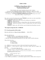
USER’S GUIDE
CAZINDS1.exe Design Masonry Software
CODE ORDA 068100002/23.12.2004
LICENSE UPDATED EVERY YEAR
Shear Capacities on the section of unreinforced masonry walls – Software
In accordance with the Methodology of failure in diagonal cracking (authors:Gh&R Popescu) -2004
and Handbook for the design of unreinforced masonry walls (approved by Ministry of Transport Construction and
Tourism, with ID:MP 001-96 ORDIN nr. 63/N/16.07.1996 )
(General Manager of Handbook and coauthor Design and Research Eng., 1st degree Rodica Popescu and coauthor
Design and Research Eng., 1st degree Gh. Popescu )
*
The software reads the file with input data named CAZIN.INP, created with a text editor (under DOS or
Windows); after running results the next output files:
CAZIN.OUT – with the results on the element (wall) containing some commentaries;
CAZIN.DAT – with the input data;
CAZIN.CAP – with the shear capacities to diagonal failure of the walls in the three stages: F, C, U;
CAZIN.ASO – with the shear capacities associated to bending moment of the walls in the three
stages: F,C,U;
CAZIN.TBL - with the values of Ψ coefficient, respectively 1/q calculated depending on capacities
The template of input data file: CAZIN.INP
F1 - General proprieties of the section
M(cantilever)/S(embrasure) , Shape of section, fp,f,Htot,N,n
(A20,A1,5F8.2)
M(cantilever)/S(embrasure)
- the height of cantilever is equal with the height of the building
- the height of embrasure is equal with the height of the window or door,
(!!! The name of the element MUST begin with the two letters: M for cantilever and S for embrasure)
Shape of the active section:
D = rectangular
T = with one flange
I = with two flanges
fp=fvd ; [Kgf/cm2] = average tensile resistance of the mortar (design shear strength of masonry)
f=fd ; [Kgf/cm2] = average compressive strength of the masonry (design compressive strength of the
masonry)
Htot ; [cm]
= Total vertical height of the wall:
- the height of cantilever is equal with the height from ±0.00 on the base,
- the height of embrasure (between two holes side by side: windows or doors) is equal with the
minimum height between the two holes.
N; [Kgf]
= design vertical load – dues to:
- Self weight of the wall
- Self weight of the floor and distributed loads on the floor (with seism hypothesis)
n = εc/εu = 0.666 – report between ( ε c ) - yield strain in compression and ( ε u ) ultimate strain in compression
F2- Geometrical characteristics of the horizontal cross section
D- Rectangular
H,B
(2F8.2)
H ; [cm] = height (in plain)
B ; [cm] = thickness (in plain)
T-with one flange*
Hi, Bi, Ht*, Bt * (4F8.2)
(* see Note at the and of text)
Hi ; [cm] = height of the hart
Bi ; [cm] = thickness of the hart
Ht ; [cm] = height of the flange
Bt ; [cm] = thickness f the flanges
I- with two flanges
Hi, Bi, Ht1, Bt1, Ht2, Bt2
(6F8.2)
Hi ; [cm] = height of the hart
Bi ; [cm] = thickness of the hart
Ht1;[cm] = height of the flange 1
Bt1;[cm] = thickness f the flange 1
Ht2;[cm] = height of the flange 2
Bt2;[cm] = thickness f the flange 2
* !!!!!! Note:
Active section with one flange (T) - the calculation considers by default the flange in the left.
The results must be read considering the calculation schemes with the real position of active sections and the
direction of the seism. If the flange is on the calculation scheme in position in the right and direction of
seism is 1, must considered the results for direction 2 and for the direction 2 the results for direction 1.
2
CANTILEVER
EMBRASURE
Htot
Htot
Hi
Hi
“D” RECTANGULAR SECTION
Direction 1
B
Direction 2
Hi
“T” SECTION
Bt
At
Ai
Ht
b
Bi
Hi
“DOUBLE « T » ” SECTION
Bt1
Bt2
At1
At2
Ai
Ht1
Bi
Ht2
Hi
3