1
End To End
Optical Beam Smoke Detector
User Guide
EN
Document Number: 0044-047-01-EN
Contents:
Page:
1. Installation
3
3. In Use
14
2. Commissioning
6
4. Maintenance and Troubleshooting
17
5. Display and Indicators
18
6. User Menu
19
7. Engineering Menu
20
8. Specification
24
9. Approval Information
25
2
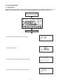
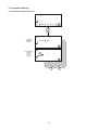
1. Installation
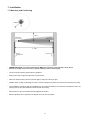
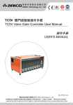
1.1 Mounting and Positioning
>30cm
Transmitter
(Clear Lens)
>30cm
Receiver
(Black Lens)
5 - 120m
Power
Supply Unit
Controller
• IMPORTANT NOTE: The infrared beam path MUST be kept clear of obstructions at all times!
Failure to comply may result in the system initiating a Fire or Fault signal.
• Check the beam spacing against local regulations
• Ensure clear line of sight from Receiver to Transmitter
• Mount on solid surfaces (structural wall or girder) and ensure fixing is rigid
• Position beam as high as possible, but with a minimum distance of 30cm from Receiver/Transmitter to ceiling
• For installations complying with UL 268/NFPA 72, the maximum distance of Transmitter and Receiver from the
ceiling must be 10% of the distance between floor and ceiling
• Mount Receiver and Transmitter directly opposite each other
• Do NOT position where personnel or objects can enter the beam path
3
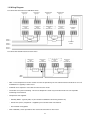
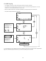
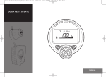
1.2 Wiring Diagram
For connection of Receivers to individual zones:
RECEIVER 1
OUTPUT
+ -
RECEIVER 2
OUTPUT
+ -
TRANSMITTER
SUPPLY
+ -
see note 1
ZONE 1 ZONE 1 +
RECEIVER 2
FAULT
N/O COM N/C
RECEIVER 2
FIRE
N/O COM N/C
RECEIVER 1
FAULT
N/O COM N/C
RECEIVER 1
FIRE
N/O COM N/C
TRANSMITTER
SUPPLY
+ -
12V to 36V DC
EXTERNAL
RESET
see note 1
EOL
EOL
EXTERNAL
RESET
ZONE 2 ZONE 2 +
SUPPLY SUPPLY +
For connection of both Receivers to one zone:
RECEIVER 1
FIRE
N/O COM N/C
RECEIVER 1
FAULT
N/O COM N/C
RECEIVER 2
FAULT
N/O COM N/C
RECEIVER 2
FIRE
N/O COM N/C
see note 1
see note 1
EOL
ZONE -
ZONE +
• Note 1: This component is the fire resistor. Its value is specified by the Fire Control Panel manufacturer. For U.S.
installations it is typically a short circuit
• ALWAYS use a separate 2-core cable for each Receiver head
• CAUTION: For system monitoring - Do not use looped wire under any terminals. Break wire run to provide
monitoring of connections
• Components not supplied:
• Schottky Diode - Typically 60V, 1A (UL-rated for installations conforming to NFPA 72)
• End Of Line ('EOL') component - supplied by Fire Control Panel manufacturer
• Fire Resistor not supplied
• After installation, check operation of Fire and Fault connection on Fire Panel
4
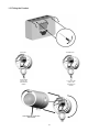
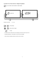
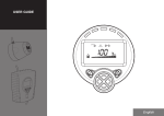
1.3 Fitting the Product
RECEIVER:
TRANSMITTER:
- +
TO
12 to 36V DC OR
SUPPLY ON
CONTROLLER
BOARD
- +
TO RECEIVER
OUTPUT ON
CONTROLLER
BOARD
LED indicator must face
downward
5
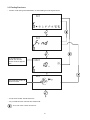
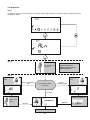
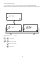
2. Commissioning
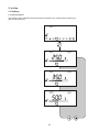
2.1 Apply Power
NOTE: One System Controller can be used to control and monitor up to two Receiver heads. The ‘#’
symbol in this guide is used to represent the number of the Receiver currently selected (1 or 2).
Apply Power to Controller,
Receiver(s) & Transmitter
3 seconds
• Receivers are not found (normal at this stage):
• Commissioned System:
• Receivers have been found but not commissioned:
• Communications fault, or no Receiver connected:
6
2.2 Enter Pass Code to Access Engineering Menu
To enter PASS CODE SCREEN in USER MENU
Default Pass Code:
1 2 3 4
Change digit
Move between digits
Accept
• An incorrect Pass Code will return the display to the Pass Code entry screen
• A partial passcode (ie. with dashes in it) will not be accepted
• Three incorrect attempts will lock access for three minutes
7
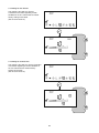
2.3 Finding Receivers
• Perform 'Find' during initial installation, or when adding or removing Receivers
As each Receiver is
"Found" the relevant
receiver number appears
here
This will be the number of
Receivers found
• Press tick to enable ‘Found’ Receivers
• Any unused Receiver channels are switched off
To re-scan if the number is incorrect
8
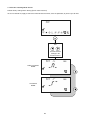
2.4 Select Receiver to be Accessed
• All Receivers need to be aligned separately
• The following sections in this User Guide explain how to align individual Receivers
9
2.5 LASER Targeting
• The LASER in the Receiver head is used to align the Receiver with the Transmitter.
• The LASER can be activated using the button on the Receiver head whilst in Engineering Menu, or via the
LASER icon in the ENGINEERING MENU as shown below.
• Move the LASER as close to the Transmitter as possible, by moving the Receiver’s thumbwheels
• The system will signal Fault while in this mode
This LASER TIMEOUT
value (MIN=1 min.;
MAX=59 mins.) may be
incremented or
decremented in 1 min.
steps by using:
DANGER
LASER RADIATION - AVOID
DIRECT EYE EXPOSURE
POWER OUTPUT < 5mW
CLASS IIIa LASER
Wavelength 630 - 680 nm
Countdown Elapsed
If it is not possible to see the LASER because of the installation environment (for example, if there is high ambient
light) then mechanically align the Receiver by eye so that it is pointing at the Transmitter.
10
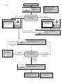
2.6 Alignment
Step 1
In alignment mode you are centring the Transmitter beam onto the Receiver and the system is adjusting its power
for optimum signal.
Step 2
Set Tx power to
maximum.
Tx
NOTE 1: Value can be
between 2 and 178.
A higher value means a
better alignment.
Step 3
Signal too
high
Rx
Green - short/long
flash
View LEDs on Rx or
LCD value
Amber short/long flash
Signal too
low
Rx
No flash
Tx
Reduce Tx
power
No flash
Rx
(SEE NOTE 1)
Proceed to Step 4
11
Adjust thumbwheels
No flash
Tx
From Step 3
Step 4
Tx
Green - flash/stop
(SEE NOTE 1)
Rx
(SEE NOTE 1)
Signal
increased
LED - no flash
LCD = between 2
and 178
Tx
Amber - flash/stop
View LEDs on Rx or
LCD value
Green - flash/stop
Reduce Tx
power
NOTE 1: Value can be
between 2 and 178.
A higher value means a
better alignment.
Adjust one
thumbwheel by
1/4 turn.
Tx
Green - short/long
flash
LCD = 180
Adjust same thumbwheel by 1/4 turn
in the same direction. Release thumbwheel and wait 1 second.
Amber flash/stop
LCD value
decreases
Tx
Green - flash/stop
LCD value
increases
Adjust same thumbwheel by 1/8 turn in
the opposite direction
Repeat step 4 for the other
thumb-wheel
12
Signal
decreased
Adjust same thumbwheel by
1/4 turn in the opposite
direction.
Tx
View LEDs on Rx or
LCD value
Rx
Press tick to accept
alignment
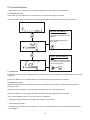
2.7 Fire and Fault Tests
• After alignment or maintenance, it is recommended that Fire and Fault tests are performed:
2.7.1 Remote Fire Test
The Remote Fire Test allows the user to perform a Fire Test from the System Controller.
The Remote Fire Test is acceptable for Fire Authority Acceptance and Routine Maintenance per UL 268-5.
Receiver Fire LED Test
The Receiver will signal 'Fire',
the System Controller will stay
Normal.
To exit without performing
test, press:
Relay / Controller Wiring
Test
The System Controller signals
'Fire' to the Fire Control Panel.
To exit, press either:
OR
2.7.2 Fault Test
Completely cover the Receiver taking less than 2 seconds to do so. The Controller will indicate Fault after the Fault
Delay time.
Uncover the Receiver. The Controller will return to Normal state after approximately 5 seconds.
2.7.3 Manual Fire Test
Although the Remote Fire Test adequately tests the Fire response of the system it is also possible to perform a
Manual Fire Test.
Slowly half-cover the Receiver. The Controller will indicate Fire after the Fire Delay Time.
Uncover the Receiver. The Controller will return to Normal state after approximately 5 seconds.
If Fire Latching Mode is set to ‘On’ then clear the Fire condition by:
• Applying a voltage between 5V and 40V to the external reset terminal
• Entering the Pass Code
• Disconnecting the power to the Controller for more than 20 seconds. System will clear latched fire when power
is re-applied.
13
3. In Use
3.1 Settings
3.1.1 Fire Threshold
This setting is the threshold at which the Receiver will detect a fire. Default factory setting=35%.
(Set for each Receiver).
14
3.1.2 Delay To Fire Screen
This setting is the delay the System
Controller uses before signalling a FIRE
condition to the Fire Control Panel. Default
factory setting=10 seconds.
(Set for each Receiver).
3.1.3 Delay To Fault Screen
This setting is the delay the System Controller
uses before signalling a FAULT condition to
the Fire Control Panel. Default factory
setting=10 seconds.
(Set for each Receiver).
15
3.1.4 Set Fire Latching Mode Screen
Default factory setting=Non-Latching (Set for each Receiver).
To clear a latched fire, apply 5-40V to the External Reset terminal, enter the passcode, or power cycle for 20s.
Use
to scroll between
settings in the
Receiver Menu.
NON-LATCHING
MODE
LATCHING
MODE
16
4. Maintenance and Troubleshooting
4.1 System Maintenance
The system will automatically compensate for dust build-up by changing the Compensation Level. However, it is
recommended that the Transmitter and Receiver lenses are cleaned periodically with a soft lint-free cloth. The
system should be isolated from the Fire Control Panel before cleaning takes place. After cleaning, verify that the
system is operating normally by following the Alignment procedure and the Fire and Fault Tests described in this
User Guide.
4.2 Error Codes
Error
Code
Meaning
Corrective Action
E-00
AIM not recognised
Refer to manufacturer for further technical
assistance
E-01
Receiver Communications Fault
Check wiring between Controller and
Receiver
E-02
‘Find’ not successfully executed
Follow ‘Find’ process
E-03
Compensation limit reached
Clean and re-align system
E-04
Receiver missed too many readings, or lost sync
with the Transmitter
Ensure clear line of sight from Transmitter to
Receiver
E-05
Receiver is not aligned
Follow alignment procedure
E-06
Rapid Obscuration Fault
Ensure clear line of sight from Transmitter to
Receiver
E-07
Signal High Fault
Ensure there is no stray light from another source
E-15
Signal too low at end of alignment
Ensure clear line of sight from Transmitter to
Receiver. Ensure alignment of Transmitter AND Receiver. Do not exit
whilst alignment status LEDs are still flashing
E-16
Signal too high at end of alignment
Follow alignment procedure again. Do not exit
whilst alignment status LEDs are still flashing
E-18
Short circuit detected on communications
between Controller and Receiver
Check wiring between Controller and Receiver
E-19
IR signal integrity fault
Check there are no strong sources of light near the Receiver, or direct
sunlight
E-20
Ambient light fault
Check there are no strong sources of light near the Receiver, or direct
sunlight
E-21
Power too low fault
Check power supply to Controller
17
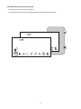
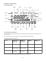
5. Display and Indicators
5.1 LCD Icon Layout
Receiver
Number
Latched /
Reset
Degrees
& LED
Setting
Minutes
Seconds
Compensation
Level
User
Prompt
Signal
Strength
Fire
Controller
Setting
External Reset
Fault
Warning
Busy
%/V
System Locked /
Unlocked
Address Setting
Alignment Mode
Laser
Bar Graph
Delay
To Fire
Beam
Alignment
Receiver
Find
LASER
Targeting
Receiver
Settings
Delay To
Fault
Fire
Threshold
Controller
Settings
Fire
Test
5.2 Receiver Status Indicators
The Green and Amber LEDs flash during alignment to indicate alignment status. Refer to alignment procedure for
further information.
The Red LED will flash every 10 seconds when a fire is detected during normal operation.
5.3 Controller Status Indicators
Condition
(LEFT HAND LED)
RECEIVER 1
STATUS LED
(MIDDLE LED)
RECEIVER 2
STATUS LED
FIRE RELAY
STATE
FAULT RELAY
STATE
Normal
No Flash
No Flash
Open
Closed
Fault (Trouble)
Flashes AMBER
every 10 seconds
Flashes AMBER
every 10 seconds
Open
Open
Fire (Alarm)
Flashes RED every
10 seconds
Flashes RED every
10 seconds
Closed
Closed
System Controller Status LED (Right-hand LED) flashes green every 10 seconds.
18
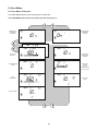
6. User Menu
6.1 User Menu Overview
The USER MENU allows system settings to be viewed only.
The USER MENU will timeout 15 minutes after the last key press.
CONTROLLER
SOFTWARE
VERSION
CONTROLLER
LED ON/OFF
STATUS
RECEIVED
SIGNAL %
RECEIVER
SOFTWARE
VERSION
COMPENSATION
LEVEL
RECEIVER
STATUS
(Refer to
Troubleshooting
for error codes)
FIRE
THRESHOLD
DELAY TO
FAULT
DELAY TO FIRE
19
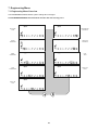
7. Engineering Menu
7.1 Engineering Menu Overview
The ENGINEERING MENU allows system settings to be changed.
The ENGINEERING MENU will timeout 60 minutes after the last key press.
RECEIVER
FIND
CONTROLLER
SETTINGS
LASER
TARGETING
RECEIVER
SETTINGS
BEAM
ALIGNMENT
FIRE
TEST
FIRE
THRESHOLD
DELAY TO
FAULT
DELAY TO
FIRE
20
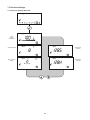
7.2 Receiver Settings
7.2.1 Receiver Settings Overview
VIEW
SIGNAL
STRENGTH
COMPENSATION
SOFTWARE
RX GAIN
SET LATCHING
MODE
HARDWARE
RX GAIN
21
7.3 Controller Settings
7.3.1 Controller Settings Overview
PASSCODE
CHANGE
SCREEN
CONTROLLER
STATUS
LED ON/
OFF
SCREEN
22
7.3.2 Passcode Change Screen
• This screen allows the user to change the Pass Code used to access the ENGINEERING MENU.
NOTE: The number being altered flashes. A partial passcode (ie. with dashes in it) will not be accepted.
Default Pass Code:
1234
Change digit
Move between digits
Save new Pass Code
Abort change
23
7.3.3 Controller Status LED ON/OFF Screen
This setting controls whether the System Controller Status LED will
flash.
OR
Toggle ON or OFF
Confirm setting
Abort change
8. Specification
Parameter
Operating Range:
Operating Voltage Range:
Transmitter Current:
Value
5 to 120m
12 to 36V DC +/- 10%
8mA
Alarm Current (Controller with 1 or 2 Receivers):
14mA
Quiescent Current (Controller with 1 or 2 Receivers):
14mA
Fault Current (Controller with 1 or 2 Receivers):
14mA
Power Down Reset Time:
Fire and Fault Relay Contacts:
Operating Temperature:
Storage Temperature:
Receiver Tolerance to Beam Misalignment at 25% sensitivity:
>20 seconds
VFCO 2A@ 30 Volts DC, resistive
-10°C to +55°C (non-condensing)- EN
-20°C to +55°C (non-condensing)- UL
-40°C to +85°C (non-condensing)
+/- 2.5%
Transmitter Tolerance to Beam Misalignment at 25% sensitivity: +/- 0.7%
Selectable increments of 1% from 10% to 60%.
Major selectable increments are 25, 35 and 50%
2-30s, individually selectable
850nm
203 x 124 x 73mm (W x H x D)
74 x 74 x 161mm (W x H x D)
606g
Fire Alarm Thresholds:
Delays to Fire and Fault:
Optical Wavelength:
Control Unit Dimensions:
Transmitter & Receiver Dimensions:
Weight (Control Unit):
Weight (Transmitter & Receiver inc. brackets):
207g
Red = Fire (one for each Receiver)
Amber = Fault (one for each Receiver)
Green = System OK
LED Indications - Control Unit:
Red = Fire. Green and Amber indication LEDs for
single-person alignment
IP54
93%, (non-condensing)
TBC
S3417 (volume 6)
UL94 V0 PC
LED Indications - Receiver:
IP Rating:
Relative Humidity (Max.):
CPD Reference:
UL File:
Housing Construction (Controller/Transmitter/Receiver):
24
9. Approval Information
9.1 UL Approval Information
• UL File Number: S3417
• All installations should comply with NFPA72. No liability will be accepted for applications not conforming to
NFPA regulations.
Distance betweenTransmitter Fire Threshold Range
and Receiver
5 - 10m (16.4 - 32.8 ft )
25%
20 - 40m (65.6 - 131.2 ft )
25 - 45%
10 - 20m (32.8 - 65.6 ft )
40 - 60m (131.2 - 196.8 ft )
60 - 80m (196.8 - 262.5 ft )
80 - 100m (262.5 - 328.1 ft )
100 - 120m (328.1 - 393.7 ft )
25 - 30%
35 - 60%
45 - 60%
55 - 60%
60 %
9.2 European Approval Information
• Complies with EN54-12 for sensitivity levels between 25% and 35%, with a maximum delay to fire of 20
seconds.
25