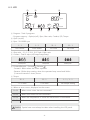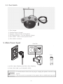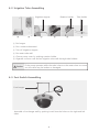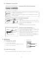
1
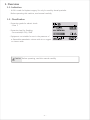
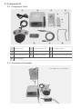
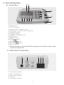
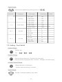
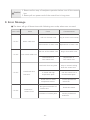
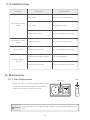
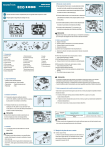
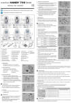
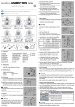
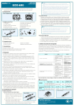
You have required to read this manual carefully before operating this machine.
Contents
1. Overview
p1
2. Precaution
p2
3. Components
p3
4. Part Introduction
p4
5. Main Power Input
p6
6. How to Install
p7
7. Operation
p9
8. Error Message
p12
9. Troubleshooting
p13
10. Maintenance
p13
11. Specification
p15
12. Disposal
p16
13. Warranty
p16
1. Overview
1-1. Indication
- Ki-20 is made for Implant surgery. It’s only for used by dental specialist.
Before operating this machine, read manual carefully.
1-2. Classification
- Protection grade for electric shock
: Class Ⅰ
- Protection level for flooding
: Foot switch(Ki-F20) / IPX8
- Equipment not suitable for use in the presence of
a flammable anaesthetic mixture with air or oxygen
or nitrous oxide.
Caution Before operating, read this manual carefully.
-1-
2. Precaution
Danger
- The system may be subject to malfunction when used in the presence of electromagnetic interfe
-rence.
- Do not locate the system in the vicinity of other devices that possibly emit electromagnetic inter
-ference.
Warning
- Ki-20 is designed for use by dental professionals only.
- Special care must be taken to maintain patient safety while in use.
- Read this user’s manual thoroughly and understand functions of individual components complet
-ely before use.
- Make sure the product is in good working condition prior to use. If there is no any abnormal co
-ndition, continue to use the product.
- Before using the product, the test run must be performed to check if the product is working no
-rmally.
- If there is any abnormal condition, including excessive vibration, noise and heat while using the
product, immediately turn off the power to stop using and contact your local dealer for repair.
- To prevent personal injury or product demage, it is required to check if the motor handpiece has
been turned off before changing the file.
- Violent shocks, such as dropping the product, may cause product damage.
- Do not disassemble the motor handpiece.
- Before cleaning the product, be sure to turn off the power and then wipe the motor handpiece
with a dry cloth.
- Do not use any organic solvent to clean motor handpiece and control box.
- Transport and storage conditions
The product must be transported and stored at temperature of -20°C~40°C, atmosphere pressure
of 700~1060 HPa, and humidity of 0~90%. If the conditions are not satisfied, the product may
not work normally.
Caution
- For the follow up service and spare parts, please contact your local dealer.
- Ensure that the product is not exposed to dust, sulfur or salt.
- Use the recommended files only.
-2-
3. Components
3-1. Component Parts
①
②
③
⑥
④
⑤
⑦
⑧
⑨
⑩
①
Power cord
②
Control box(Ki-20)
③
Irrigation tube
④
Y-tube
⑤
Tube holder
⑥
Coolant hanger
⑦
Foot switch(Ki-F20)
⑧
Handpiece stand
⑨
E-type motor & Motor cord
⑩
Foot hanger
3-2. Component Assembly
※ Coolant is not included.
-3-
4. Part Introduction
4-1. Control Box
①②
⑩
③
⑪
⑫
⑬
⑤ ⑥ ⑦ ⑧ ⑨
①
②
③
④
⑤
⑥
⑦
⑧
⑨
⑩
⑪
⑫
⑬
④
Display panel
LCD – Information
Rotation holder – Irrigation tube
PUSH button – Rotation holder open/close
GEAR RATIO button
COOLANT button
FORWARD / REVERSE button
OPTIC button
MEMORY button
SPEED
button
TORQUE
button
PROGRAM
button
Motor connector
※ All these button can be operated without getting on foot switch except coolant
button and light button.
4-2. Back Side of Control Box
①
①
②
③
④
⑤
③ ④ ⑤
②
Foot switch connector
Label – Specification
Power cord connector
Fuse box
Power switch (on/off)
-4-
4-3. LCD
①
③
②
PROGRAM
rpm
F
④
N.cm
⑥
⑤
⑦
① Program : Total 9 programs
- Program memory : Optic(on/off), Rpm, Gear ratio, Coolant, F/R, Torque
② Optic (on/off)
③ Rpm : 20~80000 rpm
1:1
1:2
20 : 1
32 : 1
600~40000
1200~80000
30~2000
20~1200
④ Gear ratio – 1:1, 1:2, 20:1, 32:1 Total 4 Gear ratio
⑤ Coolant : Total 4 steps (off/1step/2step/3step)
50ml/min
75ml/min
90ml/min
⑥ Forward/Reverse : Forward , Reverse
- Forward : Blinks when the motor operates.
- Reverse : Blinks when setting, when the operates beep sound and blinks
(2-second intervals 2 times) occurs.
⑦ Torque
20 : 1
5~70 Ncm
32 : 1
1:1 / 1:2
5~90 Ncm
No torque setting
⑧ When an error occurs, displayed on the screen.
Err 01
When micro motor has not connected.
Err 02
When foot switch has not connected.
Err 03
When the temperature of inside the transformer is overheated.
Err 04
When overload of coolant motor occurs.
Caution Special care must always be taken when handling the LCD panel.
-5-
4-4. Foot Switch
①
⑥
③
④
②
⑤
①
②
③
④
⑤
⑥
Foot hanger
Coolant button (4 steps)
Program change button (9 Programs)
F/R change button – For the direction change
Foot switch – Micro motor speed control
Foot switch connector
5. Main Power Input
USE ONLY WITH A 250V FUSE
Fuse Box
Fuse
① AC220~240V, 50/60Hz or AC100~120V, 50/60Hz)
② 2.0AL (220~240V ) or 3.15AL(100~120V)
Caution
1. To avoid electric shock, do not plug or unplug the power cord with wet
hands.
2. The unit must be connected to the power with a suitable earth ground.
-6-
6. How to install
1. The control box must be installed on a flat surface substantially uninte
-rferred with by peripheral devices. Avoid ventilation on the bottom
plate of the control box being blocked off.
Caution
2. The control box must be used in a place where indoor temperature is
maintained at a proper level (0~40°C).
3. Do not use the unit in a dirty or very hot and humid place.
6-1. Connection
Motor Cord Connection
- A motor cord connector is required to be well connected well
with a port in front of a control box by checking right connection
direction, pushing it to the end until click-sound correctly.
Foot Switch Connection
- Foot switch cord connector is required to be well connected with
a port of foot switch connect in the rear of a control box.
Power Cord Connection
- Power cord connection is required to be well connected with a
port of power connector in the rear of a control box.
Caution
- The power cord plug must be connected to the power outlet only after
making sure that all the cords have been connected properly and safely.
-7-
6-2. Irrigation Tube Assembling
Irrigation stopper
①
②
③
Rotation holder
④
Tube holder
⑤
⑥
① Put hanger.
② Put a coolant downward.
③ Turn off irrigation stopper.
④ Put water tube well.
⑤ Close a pump cover by pushing rotation holder.
⑥ Organize a motor cord and an irrigation tube well through tube holders.
Caution
- If the pump operates while the tube is bent or the water does not come
out, the tube may be broken or damaged.
6-3. Foot Switch Assembling
Foot hanger
- Assemble a foot hanger well by pushing it well into the holes on the right and left
sides.
-8-
6-4. Handpiece Connection
Contra angle and E-type motor assembling
Caution
1. Please turn the power off beforehand, when assembling and disasse
-mbling the implant angle.
2. Make sure that the implant angle is surely connected to the motor
before operation.
File insertion and removal
① Insertion
While pressing the button, insert the file into the
hole of the contra head part and try to move round
the file softly with a slight press.
② Removal
While pushing the button, pull out the file.
Connection Y-tube & Nozzle clamp
Y-tube
Internal
spray nozzle
External spray nozzle
① The internal and external irrigation is available with
internal spray nozzle and Y-tube.
② Please connect each part as the picture according
to the using bur and surgery type.
③ If the user presses the button or opens the lever
with the internal nozzle inserted, the nozzle may
be damaged during the bur change.
7. Operation
Power Switch
7-1. Operation by Hand
① Check power connector.
② Check motor cord and handpiece connector.
③ Turn on the control box.
7-2. Operation by Foot
Same as above operation by hand. And then, step on a foot switch.
-9-
ON
OFF
7-3. Setting
Gear ratio Change
1 : 1 → 1 : 2 → 20 : 1 → 32 : 1
Coolant Change
Off →
→
→
Forward / Reverse Change
Optic Change
Optic LED on & off
Memory Change
Save 9 programs.
Setting torque, speed and so on.
Press memory button for 2 seconds.
Torque Change
Torque can be adjusted by pushing buttons of
Gear ratio
Range(torque)
Variation(torque)
20 : 1
5~70
5
32 : 1
5~90
5
.
Remark
- In overload case, “88” signal will be appeared on torque sector.
- After five seconds, motor will be stopped.
Program Change
Program can be memorized up to 9 programs and it can be revised by
pushing buttons of
.
- 10 -
Speed Change
Speed can be adjusted by pushing buttons of
Gear ratio
Range(rpm)
1:1
600~400
1:2
1,200~80,000
20 : 1
30~2,000
32 : 1
20~1,250
Section(rpm)
.
Variation(rpm)
600~1,000
100
1,000~5,000
500
5,000~40,000
1,000
1,200~2,000
200
2,000~10,000
1,000
10,000~80,000
2,000
30~50
5
50~250
25
250~2,000
50
20~100
5
100~500
20
500~1,000
50
1,000~1,200
100
Remark
7-4. Setting - Foot Switch
Coolant Change
Coolant rate.
Off →
→
→
Program Change
Press the button one time : Change to the next prog.
Press the button longer(more than 2 seconds) : Change to the before prog.
Forward / Reverse Change
Change direction by F/R button.
- Reverse, beef sound every 2 seconds.
Speed Change
Increase or decrease speed by foot switch.
- 11 -
Caution
1. Please confirm stop of handpiece operation before turn off the control
box.
2. Please pull out power cord of the control box in long term.
8. Error Message
■ The alarm will go off three times with following error code, when error occurred.
Error code
Status
Cause
Pull out of motor cord.
“ Err 01 ”
Countermeasure
Plug in motor cord correctly.
Motor cable error
Disconnection of motor cord. Replacement of motor cord.
“ Err 02 ”
Pull out of foot switch cord.
Plug in foot switch cord.
Disconnection of
Replacement of
foot switch cord.
foot switch cord.
Foot switch cable error
Hard work for a long time.
“ Err 03 ”
Transformer and
heat error
Use the control box in
temperature place.
recommended place.
Break down in inside
Contact professional
Not good connection of
“ Err 04 ”
down the control box.
In closed and high
temperature sensor.
Overload of
Stop to use and cooling
coolant tube.
coolant motor
Problems of coolant parts.
- 12 -
technician.
Check tube status.
Contact professional
technician
9. Troubleshooting
Symptom
Check point
Not working of LCD
display
Not working of foot
switch
Heat problem
Countermeasure
Plug status.
Plug in motor cord correctly.
Fuse status.
Replacement of fuse.
Power switch status.
Contact professional technician.
Foot switch status.
Plug in foot switch correctly.
Trouble of ball bearing.
Contact professional technician.
Stained with foreign substance.
Clean the handpiece.
Trouble of ball bearing.
Contact professional technician.
Strong vibration
& noise
10. Maintenance
10-1. Fuse Replacement
- Check the fuse in case the power switch failed.
- Pull out the fuse box located on the back of
control box when you check the fuse.
Caution
Fuse
USE ONLY WITH A 250V FUSE
Fuse box
Be sure to turn the power off and unplug the unit before replacing the
fuse.
- 13 -
10-2. Maintenance for Control Box & Foot Switch
- Clean the control box or foot switch with alcohol after unplug.
10-3. Maintenance for Handpiece
- When cleaning the handpiece, put the head part into the water and repeat the opera
-tion and stop for 4-5 times.
- Dry it all after cleaning.
- Do not put the whole handpiece into water.
10-4. Sterilization
- We recommend an autoclave sterilization with high-pressure.
- Please, sterilize below items.
Contra angle/ E-type motor with motor cord
Caution
Please, Do not sterilize with high-pressure control box, foot switch,
ac power cord.
Autoclaving
- Remove foreign body from a handpiece.
- Put the autoclaving plug into micromotor.
- Put the handpiece into sterilizer.
Caution
1. Remove foreign body from a handpiece.
2. Do not plug out the motor cord from a handpiece.
- 14 -
11. Specification
Control Box
Model
Ki-20
AC 100~120V , 50/60Hz / AC 220~240V , 50/60Hz
Power(Input)
Output
100VA
Weight
2,606g
240(W)X225(D)X97(H)
Demension
E-Type Motor & Motor Cord
Model
Ki-MTO
Weight
265g
117(L), Ø22
Demension
Reduction gear
Contra Angle
28VDC / 40,000 RPM
Autoclaving
135℃
Model
Model
Ki-AG20
Weight
83g
Demension
97(L)
Reduction gear
20:1
135℃
Autoclaving
Autoclaving
Ø20
Angle Diameter
Foot Switch
Model
Ki-F20
Weight
1,015g
Demension
218(W)X190(D)X57(H)
Height including
a coolant bar
Handpiece Stand
Weight
Demension
165mm
101g
60(W)X130(D)X47(H)
- 15 -
12. Disposal
- If you have any inquiries, please contact a sales office you bought.
13. Warranty
- We do not quarantee the quality in case of user’s carelessness.
- 16 -
Head Office ㅣ 348, Seongseo-ro, Dalseo-gu, Daegu, 704-900, Korea
TEL +82-53-582-9000~2
FAX +82-53-581-9003
Seoul Office ㅣ #403 Cheong-am B/D 65-9,
Bongnae-dong 1-ga, Jung-gu, Seoul, 100-161, Korea
TEL +82-2-775-9023
FAX +82-2-775-9026
Website : www.saeyang.com
E-mail : [email protected]
June, 2013
201306-KI-E-01
Ver. 1-E