1
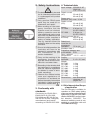
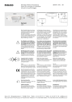
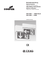
Betriebsanleitung
Systemleuchte
Zielgruppe: Elektrofachkräfte
Operating instructions
System luminaire
Target group: Skilled electricians
RZ 1506 .... 1808 CG-S
RZ 1506 .... 1808
300 80 001 640 (D)
Inhaltsverzeichnis
1 Aufbau und Maßilder ................................................ 3
1.1 Aufbau der Leuchten ............................................................ 3
1.2 Maßbilder ........................................................................ 4 - 6
2
Sicherheitshinweise ................................................. 7
3
Normenkonformität .................................................. 7
4 Technische Daten ..................................................... 7
4.1 Kurzbeschreibung / Verwendungsbereich .......................... 7
5 Installation ................................................................. 8
5.1 Montage/Lampenwechsel .................................................... 8
5.2 Typabhängige Montage ........................................................ 8
5.3 Adressierung (nur RZ 1X0X CG-S) .................................... 10
6
Instandhaltung / Wartung ........................................ 10
7
Recycling ................................................................. 10
Table of Contents
1 Construction and dimensional drawings ................ 3
1.1 Construction of the luminaires .............................................. 3
1.2 Dimensional drawings ........................................................ 4-6
2
Safety instructions ................................................... 11
3
Conformity with standards ...................................... 11
4 Technical Data ......................................................... 11
4.1 Brief description / Field of application ............................... 11
5 Installation ................................................................ 12
5.1 Mounting (Basic version) .................................................... 12
5.2 Mounting accessories ........................................................ 14
5.3 Addressing (only RZ 1X0X CG-S) ...................................... 14
6
Servicing / Maintenance ......................................... 14
7
Recycling ................................................................. 14
2
1.1 Aufbau der Leuchten
1.1 Construction of the luminaires
Beispiel/Example: RZ 1608 CG-S
Wandbefestigung
Wall mounting bracket
Leuchtenkörper
Body of luminaire
Seitenblech
Side cover
EVG13.2 CG-S
Schraube (1)
Screw
Abdeckplatte mit
Schraube
Cover plate with
screw
Netzklemmen
Mains terminals
Scheibe
Silk screen
Bild 1
Fig. 1
3
1.2 Maßbilder/Dimensional Drawings/Plans cotés
RZ 1506 CG-S/RZ 1506
Wandmontage parallel
Wall mounting in parallel
RZ 1606 CG-S/RZ 1606
Wandmontage Ausleger
Wall mounting bracket
RZ 1706 CG-S/RZ 1706
Deckenmontage
Ceiling mounting
4
1.2 Maßbilder/Dimensional Drawings/Plans cotés
Deckenausschnitt/Ceiling cut 327,0
Deckenausschnitt/
Ceiling cut
75,0 +2,5
+2,5
RZ 1806 CG-S/
RZ 1806
Deckeneinbau
Recessed
ceiling mounting
Deckenausschnitt/Ceiling cut 387,0
+2,5
RZ 1808 CG-S/RZ 1808/ Deckeneinbau/Recessed ceiling mounting
5
Deckenausschnitt/
Ceiling cut
75,0 +2,5
1.2 Maßbilder/Dimensional Drawings/Plans cotés
RZ 1508 CG-S/RZ 1508
Wandmontage parallel
Wall mounting in parallel
RZ 1608 CG-S/RZ 1608
Wandmontage Ausleger
Wall mounting bracket
RZ 1708 CG-S/RZ 1708
Deckenmontage
Ceiling mounting
6
2. Sicherheitshinweise
4. Technische Daten
EingangsDie Leuchte ist bestimmungs- spannung:
gemäß in unbeschädigtem
und einwandfreiem Zustand
Stromaufzu betreiben!
nahme (AC):
Als Ersatz dürfen nur Originalteile von CEAG verwendet Leistungsaufwerden!
nahme (AC):
Bei Durchführung von Arbeiten an der Notleuchte ist erst
die Anlage zu blockieren, der
Batteriekreis zu unterbrechen und dann das Netz
abzuschalten. Beachten Sie
dabei die unterschiedlichen
Versorgungen der Notleuchte bei Normal- und Notbetrieb. Nebenstehend ist
das Hinweisschild für die
Sicherheitsleuchte abgebildet.
Vor der ersten Inbetriebnahme muß die Leuchte entsprechend den im Abschnitt Installation genannten Anweisungen geprüft werden!
Die Notleuchtenkennzeichnung vornehmen: Stromkreis
und Leuchtennummer zuordnen und eintragen.
Die Protokollführung gemäß
der nationalen Vorschriften
ist durchzuführen (entfällt bei
automatischer Protokollierung)!
Stromaufnahme (DC):
Lampe
RZ 1X06 ..
RZ 1X08 ..
230/240 V AC
50/60 Hz
176 - 275 V DC
50 mA (6 W)
60 mA (8 W)
max. 16 VA
23 mA (6 W)
30 mA (8 W)
6 W nach
81-IEC-1040-1
8 W nach
81-IEC-1040-1
Nennlichtstrom
der Lampe:
240 lm (6 W)
450 lm (8 W)
Bemessungslichtstrom:
75 % (PhiNetz)
Schutzklasse: I
Schutzart nach
EN 60529:
IP 21
Umgebungstemperatur:
-10 °C .. +40 °C
Netzanschußklemmen:
2 x 2 x 2,5 mm²
Gewichte:
RZ 1506 ..
1,6 kg
RZ 1606 ..
1,6 kg
RZ 1706 ..
1,2 kg
RZ 1806 ..
2,4 kg
RZ 1508 ..
1,8 kg
RZ 1608 ..
1,7 kg
RZ 1708 ..
1,4 kg
RZ 1808 ..
2,5 kg
Abmessungen: siehe Maßbilder S. 4-6
Beachten Sie bei allen Arbeiten an dem Gerät die nationalen Sicherheits- und Unfallverhütungsvorschriften
und die nachfolgenden 4.1 Kurzbeschreibung/
Sicherheitshinweise in der
Verwendungsbereich
Betriebsanleitung, die mit ei- Die Rettungszeichenleuchte ist
versehen sind!
nem
für den Betrieb an CEAG
Sicherheitsbeleuchtungsanlagen
3. Normenkonformität
sowie alle Versorgungsanlagen
Konform mit: EN 60 598-1,
nach DIN VDE 0108, EMV-RichtEN 60 598-2-22, EN 1838, linie 89/336/EWG und NiederDIN 4844 und IEC 60 924 sowie spannungsrichtlinie 73/23/EWG
IEC 60 928.
geeignet. Die besondere SchaltGemäß DIN EN ISO 9001 ent- funktion wird nur mit CEAG CGwickelt, gefertigt und geprüft.
S-Technologie ermöglicht.
7
b
5. Installation
a
Halten Sie die für das
Errichten und Betrei
ben von elektrischen
Betriebsmitteln geltenden Sicherheitsvorschriften und das
Gerätesicherheitsgesetz sowie die allgemein anerkannten
Regeln der Technik ein!
5.1 Montage (Grundversion)
Lösen sie mit einem geeigneten
Kreuzschlitzschraubendreher
die Deckelschraube M4 (Bild 1)
und entfernen sie die Abdeckplatte. Schwenken sie das Seitenblech nach oben heraus.
Schließen sie die Netzleitungen
an den Klemmen L und N am EVG
an (Bild 2). Befestigen sie den
Schutzleiter an der Schraubklemmen (a) und schließen sie
alle PE-Verbindungen an den
vorgesehenen Steckverbindungen (b) an.
Bild 2
Lampenwechsel
Bild 4
Schalten Sie die Leuchte
spannungsfrei!
Zum
Lampenwechsel lösen sie mit einem geeigneten Kreuzschlitzschraubendreher die Deckelschraube M4 (Bild 1) und entfernen sie die Abdeckplatte.
Schwenken sie das Seitenblech
nach oben heraus. Drehen Sie
die Lampe vorsichtig aus der
Fassung heraus. Beim Einbau
der neuen Lampe ist auf ein sicheres Einrasten der Lampe in
die Fassung zu achten!
Bild 4a
Montage der Haltewinkel
RZ 1806/1808
Bild 4b
Haltewinkel hochgeschoben
zum Deckeneinbau
Bild 3
Haltewinkel
Einbaudecke
max. 35 mm
Abstand
8
5.2 Typabhängige Montage
RZ 1506/RZ 1508..
Wandmontage parallel
Das Leuchtengehäuse an den
Seitenwänden öffnen und danach die Frontplatte entfernen.
Durch Lösen der Muttern der
Halteschrauben das hintere
Wandmontagegehäuse lösen.
Die Leitung einführen und das
Leitungsgehäuse an der Wand
mit 2 Schrauben befestigen.
Danach die Leitung auch durch
die Leitungseinführung des
Leuchtengehäuses führen und
PE und Netz anschließen.
Das Leuchtengehäuse auf das
Leitungsgehäuse setzen und mit
den Muttern an den Halteschrauben befestigen. Optional
ist mit einem geeigneten Schraubendreher am Modul 2L-CGSL4 die gewünschte Leuchtenadresse zur Überwachung einzustellen, s. Kap. 5.2. Das
Leuchtengehäuse schließen!
RZ 1706/RZ 1708..
Deckenmontage
Lösen Sie die Befestigungsschrauben des Wandblechs,
trennen Sie die Steckklemme
und die PE-Leitung und montieren Sie das Wandblech gemäß
Maßbild 1.2 (S.4 u.6) mit mind. 3
geeigneten Schrauben an einer
tragfähigen Wand. Stecken Sie
nach erfolgtem elektrischen Anschluss (L, N, PE) die PE-Leitung und die Steckklemme sicher
auf und befestigen Sie die
Leuchte am Wandblech.
RZ 1606/RZ 1608 ..
Wandmontage Ausleger
Lösen Sie die Befestigungsschraube (1) des Wandhalters,
ziehen Sie den Befestigungswinkel heraus, lösen sie die PEVerbindung und montieren Sie
das Wandblech gemäß Maßbild
1.2 (S.4-6) mit mind. 3 geeigneten Schrauben an einer tragfähigen Wand. Stecken Sie nach
erfolgtem elektrischen Anschluss (L, N, PE) die PE-Leitung und die Steckklemme sicher
auf und befestigen Sie die
Leuchte am Wandblech.
B
RZ 1806/RZ 1808..
Deckeneinbau
Die Piktogrammscheiben sind nach den Bildern
8c und 8d zu montieren.
Beachten Sie beim Deckenausschnitt die exakten Einbaumaße gem. Maßbild 1.2 (S.5).
Montieren Sie die Haltewinkel nach Bild 4a auf
Abstand vom Gehäuse. Schieben Sie die Haltewinkel nach oben über die Gehäusekanten,B.4b.
Führen Sie das Metallgehäuse in den Deckenausschnitt ein. Schieben Sie die Montagewinkel
bis zur Einbaudecke zurück (Bild 4). Ziehen Sie
die Schrauben wieder fest.
Sichern Sie das Einbaugehäuse mit zusätzlichen Schrauben an der Deckenkonstruktion!
A
Hängen Sie das Leuchtenchassis (A) gem. Bild 5
mit den Führungssteg in die Aussparung (B) ein.
Schließen Sie die Netzleitung an den Klemmen (L)
und (N) sowie (PE) an. Sichern Sie die Leitung mit
der Zugentlastung (nur RZ 1808..) (C, Bild 6).
Führen Sie das Chassis weiter ins Gehäuse ein
und sicheren Sie es durch Einstecken in die Aussparung (D), (Bild 7).
Hängen Sie die Scheibe gemäß Bild 8 ein. Schieben Sie den Abdeckrahmen über die Scheibe.
a) RZ 1806.. : Befestigen Sie den Rahmen mit
den beiden Schrauben am Gehäuse.
Bild 5
C (nur RZ 1808..)
b) RZ 1808.. : Drücken Sie den Rahmen bis zum
deutlichen Einrasten fest. Zum Lösen drücken
Sie einen Schlitzschraubendreher in die seitlichen
Aussparungen und lösen damit den Rasthaken.
Bild 6
D
Bild 7
Bild 8b
Bild 8a
9
5.3 Adressierung (nur RZ
1X0X CG-S)
Bild 8c
Montage von Bolzen und
Piktogrammscheiben
RZ 1806/1808
Unterlegscheibe
Gegenmutter
Bolzen
Vor Montage der Leuchte muss
die individuelle Leuchtenadressierung eingestellt werden.
Hierzu ist mit einem geeigneten
Schraubendreher die gewünschte Adresse (1 - 20) am
Adressschalter einzustellen (Pfeil
auf Zahl, Bild 9). Soll die Leuchte
nicht überwacht werden, ist
immer die Stellung 0/0 einzustellen.
6. Wartung/Instandhaltung
Halten Sie die für Instandhaltung,
Wartung und Prüfung von elektrischen Betriebsmitteln geltenden Bestimmungen ein! Bei
sachgerechtem Betrieb und unter Beachtung der Montagehinweise und Umgebungsbedingungen ist keine ständige Wartung erforderlich.
7. Entsorgung/
Die Leuchten RZ 1X0X sind Recycling
nicht mit einer Überwachungselektronik ausgerüstet und ist Beachten Sie bei der Entsorgung defekter Geräte die gültinicht adressierbar.
gen Vorschriften hinsichtlich Recycling und Entsorgung.
Montagezubehör
Kunststoffmaterialien sind mit
Pendelbefestigung 0,5 m
entsprechenden Symbolen geDie
Piktogrammscheiben für RZ 170X ...
kennzeichnet.
sind seiten- und lagerichtig Bestell Nr. 400 71 348 721
zusammenzuschrauben!
Auf passgenaue Montage Pendelbefestigung 1,5 m
für RZ 170X ...
aller Kanten ist zu achten!
Bestell Nr. 400 71 348 722
Bild 8d
Montage von Bolzen und
Piktogrammscheibe einseitig
mit Ausgleichstück
Kettenbefestigung (ohne
Kette)
für RZ 170X ...
Bestell Nr. 400 71 348 723
Betoneinbaukasten
für RZ 1806 ...
Bestell Nr. 400 71 348 725
Betoneinbaukasten
für RZ 1808 ...
Bestell Nr. 400 71 341 710
Im Fall von Rücksendungen benötigen Sie von uns
eine RMA - Nummer.
Entnehmen Sie bitte weitere
Infos hierzu unserer Internetseite www.ceag.de!
- Technische Änderungen vorbehalten -
2
2
1
0
3
1
4
0
5
9
6
8
Schalter 1
7
Schalter 2
Adressschalter 1
0
0
0
...
1
1
...
...
2
2
...
2
Bild 9 Adressschalter
(nur RZ XXXX CG)
10
Adressschalter 2
0
1
2
...
0
1
...
...
0
1
...
9
Leuchtenadresse
Überwachung aus
1
2
...
10
11
...
...
20
nicht zulässig
...
nicht zulässig
2. Safety Instructions 4. Technical data
The device shall only be used
for its intended purpose and
in undamaged and perfect
condition!
Only genuine CEAG spare
parts may be used for replacement and repair!
When working on the emergency luminaire first the
system must be blocked,
battery operation must be
interrupted and mains must
be cut off. Pay attention to the
different power supplies in
mains or battery operation.
The fig. beside shows the
indication label on the safety
luminaire.
Prior to its initial operation, the
luminaire will have to be
checked in accordance with
the instructions as per
section Installation!
Carry out the marking of the
emergency luminaire: Assign the circuit and the luminaire No. and enter them.
Recording in the minutes shall
be performed in compliance
with the national regulations
(is deleted in case of automatic recording).
Observe the national safety
rules and regulations for
prevention of accidents as
well as the safety instructions
included in these operating
instruction marked with
3. Conformity with
standards
Input voltage: 230/240 V AC
50/60 Hz
176 - 275 V DC
Rated current
(AC):
50 mA (6 W)
60 mA (8 W)
Power consumption (AC): max. 16 VA
Rated current
(DC):
23 mA (6 W)
30 mA (8 W)
Lamp:
RZ 1X06 ...
6 W acc. to
81-IEC-1040-1
RZ 1X08 ...
8 W acc. to
81-IEC-1040-1
Rated luminous flux of
the lamp:
240 lm (6 W)
450 lm (8 W)
Rated luminous flux for
emergency
operation:
75 % (phimains)
Insulation class: I
Protection category acc.
to EN 60529: IP 21
Perm. ambient
temperature: - 10 °C ..+ 40 °C
Supply
terminals:
2 x 2 x 2.5 mm²
Weight:
RZ 1506 ..
1.6 kg
RZ 1606 ..
1.6 kg
RZ 1706 ..
1.2 kg
RZ 1806 ..
2.4 kg
RZ 1508 ..
1.8 kg
RZ 1608 ..
1.7 kg
RZ 1708 ..
1.4 kg
RZ 1808 ..
2.5 kg
Dimensions: see dimensional
drawings on
pages 4-6
4.1 Brief description/Scope
of application
The Exit luminaire is suitable for
operation on CEAG safety lighting
systems as well as on all power supply
Conforming to: EN 60 598-1,
systems acc. to DIN VDE 0108, EMC
EN 60 598-2-22, EN 1838,
directive 89/336/EEC and low potenDIN 4844 and IEC 60 924 as
well as IEC 60 928. Designed, tial directive 73/23/EEC. The
advanced switching mode is only
manufactured and tested
according to DIN EN ISO 9001. available in combination with new
CEAG CG-S technology.
11
b
5. Installation
a
For the mounting and
operation of electrical
apparatus, the respective national safety regulations
as well as the general rules of
engineering will have to be observed.
5.2 Mounting of individual
types
RZ 1506/1508 ...
Wall mounting
Open the light fitting enclosure at
the side frame and remove the
front cover. Loose the fixing
screws by loosing the nuts to
dismantle the mains connection
5.1 Mounting (Basic verenclosure. Introduce the cable
and fix the mains connection
sion)
Use a suitable recessed-head enclosure to the wall.
screwdriver to open the cover After that also the cable must be
introduced through the light fitting
plate screw M4 (fig 1, page 3)
enclosure and than be connecand remove the cover plate.
ted to the PE and mains.
Swing the sideplate upwards
Optionally, the desired luminaire
out of the enclosure. Connect
line cable to the terminals L and address can be set for
monitoring with an appropriate
N at the ballast. Connect the
screwdriver, see chapter 5.2.
protective conductor (PE) to
Put the light fitting enclosure on
the destined terminal (a) and
the mains connection enclosure
connect all other protective
and fix it with the nuts.
conductors to the destined
Now close the enclosure.
plug connections (b).
fig.10
Lamp replacement
make sure that the
luminaire is disconnected from the voltage!
Use a suitable recessed-head
screwdriver to open the cover
plate screw M4 (fig 1, page 3)
and remove the cover plate.
Swing the sideplate upwards
out of the enclosure. Remove
carefully the lamp by turning
from the lampholder (fig 11).
For installation the new lamp
make sure the proper fit into
the lampholder by click into
fig. 11
Holding angle
Mounting ceiling
max. 35 mm
RZ 1706/1708 ...
Ceiling mounting
Unscrew the screw (1) (page 3)
of the wall bracket, disconnect
the PE-conductor from the plug
and mount the wall bracket onto
a good bearing wall with min. 3
suitable screws accd. dimensional drawings on page 4-6.
After connection of mains lines
(L, N, PE) plug securely the protective conductor (PE) and the
plug terminal. Fix the enclosure
to the wall bracket.
RZ 1606/RZ 1608..
fig. 12
fig. 12a
Mounting of the holding angle
RZ 1806/1808
fig. 12b
Holding angle uplifted for recessed ceiling mounting
Displacement
12
Wall mounting bracket
Loose the fixing screw (1) of the
wall bracket, pull it out of the fixing
bracket, now loose the PEconnection and mount the wall
sheet acc. to drawing 1.2 with 3
suitable screws.
After occured connection (L, N,
PE) put the PE-connector and
the terminal on and fix the light at
the wall sheet.
RZ 1806/RZ 1808..
B
Recessed ceiling mounting
The panel must be mounted according to fig.
18a and 18b.
For the ceiling cut-out observe the exact
fitting dimensions you find in the dimensional drawing on page 5 (see fig 1.2).
Mount the holding angle as you see in figure 12a.
Push the holding angle upwards via the
enclosure, figure 12b.
Insert the enclosure in the ceiling cut-out. Push
the mounting angle back to the mounting ceiling
A
(see fig. 12). Now tighten the screws again.
Ensure the enclosure by using an additional fixing to the ceiling construction.
Fasten the luminaire chassis (A) accd. fig. 13 with
fig. 13 the guide rib into the cutout (B). Connect the mains
cable to the terminals (L) and (N) as well as (PE).
Fix the cable with the cable clamp (only RZ 1808..,
C, fig. 14).
C (only RZ 1808 ..)
Continue inserting the chassis into the enclosure
and fasten it by fixing into the cutout (D, fig. 7).
Mount the sink screen accd. to fig. 16.
a) Press the cover frame over the screen onto the
enclosure and fix it with the two screws.
b) Press the cover frame over the screen onto
the enclosure and click it into place. For dismounting press a screwdriver into the slot an remove
the frame.
fig. 14
D
fig. 15
fig. 16b
fig 16a
13
fig.18a
Mounting of the bolt and the
legend panals
Washer
Bolt
Lock nut for
bolt
5.3. Addressing (only RZ
1X0X CG-S)
Mounting accessories
Pendulum set 0.5 m
for RZ 170X ...
Order No. 400 71 348 721
Pendulum set 1.5 m
for RZ 170X ...
Order No. 400 71 348 722
Chain suspension (without
chain)
for RZ 170X ...
Order No. 400 71 348 723
Concrete mounting box
for RZ 1806 ...
Order No. 400 71 348 725
The legend panels must
be mounted true sided
and in correct positional
arrangement. While
mounting take care that
the panels suite together!
Concrete mounting box
for RZ 1808 ...
Order No. 400 71 341 710
6. Servicing/
Maintenance
Observe the relevant national
regulations which apply to the
maintenance, servicing and
check of electrical apparatus
(in Germany DIN VDE 0105,
part 9)! On condition of an appropriate operation and of observing the mounting instructions and environmental conditions, no permanent servicing
will be required.
fig. 18b
Mounting of bolt and panel
single-sided with levelling
piece
2
2
1
0
Switch 1
3
1
4
9
6
0
5
8
7
Switch 2
fig. 17 Address switch
(only RZ 1X0X CG-S)
Address switch 1
0
0
0
...
1
1
...
...
2
2
...
2
Before fitting the luminaire, the
addressing of the individual
luminaires will have to be performed. To do so, the desired
address (1 - 20) is set on the
address switch by means of a
suitable screw driver (Arrowhead to No., fig. 17). If the
luminaire should not be monitored the code 0/0 has to be
selected.
The luminaire RZ 1X0X is not
equipped with monitoring circuit and will not be
addressable.
Address switch 2
0
1
2
...
0
1
...
...
0
1
...
9
Luminaire address
Monitoring off
1
2
...
10
11
...
...
20
not permissable
not permissable
14
7. Disposal/
Recycling
When a defective apparatus is
disposed of, the respective
national regulations on waste
disposal and recycling will
have to be observed. Plastic
parts have been provided with
respective symbols.
In case of returns you
need a RMA - number
from us. For further
information
see
www.ceag.de!
-We reserve the right to carry
out technical changes!-
15
300 80 001 640(D)/ X /09.07/
CEAG Notlichtsysteme GmbH
Senator-Schwartz-Ring 26
D-59494 Soest / Germany
Telefon + 49 29 21/69-870
Telefax + 49 29 21/69-617
Internet http://www.ceag.de
E-Mail
[email protected]