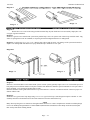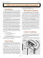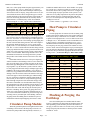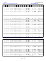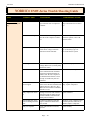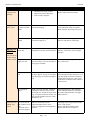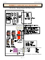
1
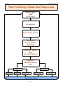
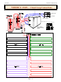
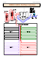
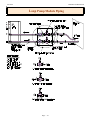
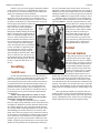
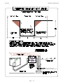
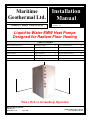
Maritime
Geothermal Ltd.
NORDIC® models EMW-45-55-65
Installation
Manual
Revision 4.0
Liquid-to-Water EMW Heat Pumps
Designed for Radiant Floor Heating
Table of Contents
Water Well Requirements .....
3
Groundloop design..............
13
Electrical Requirements ...........
22
Optimum Placement .......................
5
Circulator pumps ………....
15
Performance Tables..............
23
Plumbing the Heat Pump ................
5
Loop Flushing & antifreeze......
17
Trouble Shooting Guide ………..
26
Safety Controls ..............................
7
Engineering Data ................
19
Ranco® Aquastat Controls ……..
29
Starting the Heat Pump ...................
11
General Specifications ............... 20
Electrical Diagrams .....................
31
Maintenance ..................................
11
EMW Series features ………… 21
Warranty ...................................
35
Water Well or Groundloop Operation
Maritime Geothermal Ltd.
P.O. Box 413
Petitcodiac, N.B.
E0A 2H0
Email: [email protected]
www.discribe.ca/nordic
13-Feb-00
Maritime Geothermal Ltd.
Water Well Energy Module Heat Pump System
Energy Input:
Solar
Geothermal
Groundwater
Water Pump System
NORDIC®
Energy Module
Heat Pump
Fan Coils / Infloor
Heat
(Heat Distribution)
Disposal of
thermally altered
water
Surface
Irrigation
Domestic
Subsurface
Pond/Lake
Return Well
Underground Water
Page .... 2
Leaching
Maritime Geothermal Ltd.
13-Feb-00
NORDIC® EM Water Well System Prerequisites
There are five specific parts or sub-systems to a groundwater heat pump installation:
The source of energy (groundwater)
Water Well
The method of supplying energy to the heat pump
Water Pump System
Converting the energy to a useable form
Heat Pump
Distributing the heat
Infloor Heat / Fan Coil Units
Returning the exhaust water to the earth for reheating
Water disposal
Water Well Requirements
1.
2.
3.
4.
5.
A DRILLED well of 5'' diameter or larger.
Well casing properly sealed or grouted into rock.
Water flow preferably entering well at a depth of 75 ft. or
more.
Temperature of well at least 40° F. (Normally 45+ °F.)
Well must be able to supply requirements of BOTH heat
pump and residence usage at the same time with maximum drawdown from static level of 30 ft.
The Heat Pump
A heat pump with Btu output capable of heating the
home in all winter weather conditions should be selected using a “rule of thumb” as follows:
Water Requirements For
Nordic® Heat Pumps
Model
Heat Pump
Home
Total
Nordic EMW-45
7 Igpm
3
11
Nordic EMW-55
10 Igpm
3
13
Nordic EMW-65
12 Igpm
3
15
Note: These are minimum water requirements based on an
entering water temperature of 46° F.
Igpm = Imperial gallons per min.
Water Pump System
1.
2.
3.
4.
A submersible pump is generally required. Must be able
to pump the required water flow listed above at a minimum of 30 psig. at the dynamic pumping depth of your
well.
Make sure you select the pump using the pump manufacturers pump chart.
Use a minimum of 30 gal. equivalent air bladder tank.
Make sure the pump will be able to pump the required
flow for the heat pump while maintaining 40 psig. on the
water lines for usage in the rest of the home.
Page .... 3
Model
Sq. Ft of Home*
Nordic EMW-45
1800
Nordic EMW-55
2700
Nordic EMW-65
3500
NOTE: Rule of thumb, use proper heat load software to
determine exact requirements
Maritime Geothermal Ltd. recommends that anyone considering the installation of a heat pump in their home or office
have a professional heat loss / load calculation prepared on
the building to determine the heating and cooling requirements. The correct sizing of the heat pump to the home can
only be properly accomplished with the use of specialized
software programs designed for this job.
Discharge Water Methods
1.
Although we highly recommend it, you do NOT necessarily have to have a return well.
2. Some of our customers do one of the following with their
return or waste water:
A. Run it into a drain or ditch.
B. Pond, river or stream.
C. Leaching field.
In most instances if you run the water right out on
top of the ground it will soak back into the ground in less than
50 ft. of travel. If suitable care is taken to insure that the drain
pipe runs downhill and the end of the pipe is protected by a
bale of hay or spruce bows etc. the end of the pipe will not
freeze. When snow comes it will usually cover the entire
process much like a small spring.
The above information is intended to give the prospective user/purchaser some insight as to the general requirements for a successful application of the NORDIC® heat
pump.
13-Feb-00
Maritime Geothermal Ltd.
NORDIC® EMW Series - Open Loop Disposal Methods
A. Single Well (Pump & Dump)
Two Well System
C
Tile Bed or Leaching Field
Page .... 4
Maritime Geothermal Ltd.
13-Feb-00
When setting up the unit, Maritime Geothermal Ltd.
recommends the installation of a water flow meter on the discharge line so that the exact amount of water flowing can be
When the heat pump reaches it's destination it should
determined at a glance. Once the correct flow of water has
be unpacked to determine if any damage has occurred during
been established and determined to be consisshipment. Any visible damage should
tent, the water flow meter could be removed
be noted on the carrier's freight bill and
In to Heat Pump
from the line.
a suitable claim filed at once.
NOTE: Installing unions at each end of the
Brass fitting on
meter and similar unions on a piece of pipe
The heat pump is well conwater lines to
of the same length, allows the user to insert
structed and every effort has been made
heat Pump
the meter in the line whenever the flow of
to insure that it will arrive intact, howwater is to be checked and then remove the
ever it is in the customer's best interest
meter so that it does not deteriorate from day
to examine the unit thoroughly when it
Water (IN)
to day usage
arrives.
and (OUT)
Plumbing lines, both supply and dislines
charge, must be of adequate size to handle
the water flow necessary for the heat pump.
1/8”
D
stem
ThermomeFor distances less than 40 ft. from the presThe location of liquid-to water
ters
&
Pressure
gauges
sure tank, 3/4'' copper or plastic lines should
heat pump inside the home should be
attached
through
P/T
port.
be run while for longer distances we recomdetermined by:
mend that 1'' plastic or copper lines should be
1. The ease at which piping runs
run to the heat exchanger. Similarly, a 1'' line
can be connected to the inshould be run from the discharge pipe to the
floor heating headers on the
method if disposal.
output side of the unit.
2. Space availability in a mechanical room for the heat
Install a P/T (Pete’s Plug) plug on the Water (IN) and
pump and associated piping.
Water
(OUT) lines just outside the heat pump so that it is
3. Ease of access to the water well supply and discharge
easy
to
record the water in and out temperatures and
lines or groundloop lines.
pressures
accurately.
If possible the six main service doors should remain
Ideally there will be water flow available in excess
clear of obstruction for a distance of (2) two ft. so that servicof the requirement of the heat pump. In such a situation the
ing and general maintenance can be carried out with a miniproper pump can be selected to maintain a pressure of 30 to
mum of difficulty. Raising the heat pump off the floor a few
40 psig. on the lines when the heat pump is operating.
inches is generally a good practice since this will prevent unHowever in some cases a well can supply a heat pump only if
necessary corrosion of the bottom panel of the unit.
the
We recommend that the heat pump be placed on a
piece of 2'' Styrofoam covered with 1/4'' plywood. The Styrofoam will smooth out any irregularities in the cement floor
while the plywood will distribute the weight of the NORDIC® unit evenly over the Styrofoam. This process will also
deaden the compressor noise emitted from the bottom of the
cabinet.
Unpacking
Placement
As an alternative, several pieces of 2''x 4'' lumber can
be placed under the unit running from the electrical connection side to the opposite side of the heat pump. Laying the 2''x
4'''s in this manner will give the best support since they will
be at right angles with the internal steel compressor and heat
exchanger support.
Plumbing the Heat Pump
(water well application)
When installed on a water well, the NORDIC® heat
pump must be supplied with an adequate water supply, since
in essence, water is the fuel for the unit. It is imperative that
the flow requirements listed in the engineering section be
closely adhered to.
Page .... 5
Fittings and accessories available for P/T
plug application to heat pump.
13-Feb-00
Maritime Geothermal Ltd.
NORDIC® EMW – Closed Loop Connections
From Loops
To Loops
Pump Module
Energy Module
(Loop Connections
Shown)
Page .... 6
Maritime Geothermal Ltd.
13-Feb-00
minimum requirement for water is used.
Water Disposal Methods
Supply water flow to the heat pump can be controlled very accurately by the installation of a reverse action
pressure valve in the supply water discharge line of the unit.
If the unit is a heating / cooling unit then a dual high pressure / low pressure valve or a pair of valves must be installed.
Another method of regulating the flow is by the use
of a “DOLE” valve. This valve will automatically control the
amount of water flowing through it by varying the diameter of
a flexible rubber orifice through which the water passes. If
either of such valves is needed they can be supplied and installed by your dealer.
All water line valves on both the supply and discharge lines should be either BALL or GATE valves since a
GLOBE valve will create too much restriction across the line
possibly causing the heat pump to trip out on it's low pressure
safety cutout control as a result of insufficient water flow.
Exposed water lines will have a tendency to sweat
when the heat pump is in operation, therefore it is recommended that both the water supply and discharge lines be insulated with suitable insulation.
Hot Water Connections
Connection to the hot water generator feature of the
heat pump is accomplished by teeing into an electric or oil
fired hot water tank with a capacity of 40 gal. minimum. A
typical piping diagram is shown on page 6 in this manual. Be
sure to note the position of the check valve and the direction
of water flow.
One should be sure the tank is filled with water and
is under pressure before activating the heat pump. Slightly
loosen the copper union on the hot water discharge pipe to
allow air to escape from the system before the unit is started.
This step will make certain that the water circulator is flooded
with water when it is started.
Since the pump is water lubricated, damage will occur to the
pump if it is run dry for even a short period.
The union on the discharge water line may have to be purged
of air several times before good circulation is obtained. A
hand placed several feet down the line will sense when the
water is flowing.
The thermostats on the domestic hot water tank should
be set to 100°F. since the heat pump has an internal thermostat set at a high of 115°F. By setting the tank thermostats as
described, the heat pump will try to keep the tank above the
cut-in point of the electric element settings thus generating
hot water from the heat pump only. During periods of high
demand, the electric elements may energize to help make hot
water.
NOTE: If (2) shut-off valves are located on the hot water
lines, be sure that the valves are open when the heat pump is
operating. If both valves are closed when the heat pump is
operating, water will expand in the hot water heat exchanger and could cause damage to the hot water circulator
pump.
Page .... 7
Water disposal methods vary from area to area however some consideration should be made to prevent the cooled
discharge water from immediately coming in contact with the
supply source. Generally speaking, returning water to a
second well, pond lake or stream is acceptable while returning water to the same well will usually cool the water
so much that the heat pump will shut off on it's low pressure / temperature safety control.
A return well should be a minimum of 80 ft. from the
supply well for residential applications. The water returned to
the well will not be necessarily be pumped into the same aquifer, depending on underground conditions, but the return well
does have to be able to supply the same quantity of water as
the amount you wish to recharge into it.
If the static level (level when not being pumped) of a
well is high (10 to 20 ft. from the surface) it may be necessary
to place a watertight well cap on the well to keep the return
water from flowing out the top of the well. This cap is commonly required since a certain amount of pressure is needed
to force the return water back down the well if the static level
is high.
Return wells are not always the answer and to some
it may be more satisfactory to pump the water to a pond or
away into the woods.
Water recharged naturally through percolation into the soil is
an alternative to a recharge well. The water discharged will
generally soak into the ground within a distance of 50 to 100
ft. If care is taken to make sure the end of the pipe does not
freeze then this method of disposal works well.
Safety Controls
The NORDIC EMW series heat pump has two built-in safety
controls which are designed to protect the unit from situations
which could damage it.
A. LOW REFRIGERANT PRESSURE (heating mode)
The low refrigerant pressure control is designed to
shut the unit down if the refrigerant evaporating pressure becomes too low thus risking the danger of freezing conditions
in the evaporator.
There are only (4) reasons why this control would
activate and they are:
1. Low water flow. (See requirements for each model)
2. Low water temperature. (Below 40 °F.)
3. Dirty or fouled heat exchanger.
4. Low refrigerant charge.
B. HIGH PRESSURE CONTROL
The second safety control is a high pressure safety limit
which monitors compressor discharge pressure. This device
will not normally trip unless the water level is low in the internal storage tank. Such a situation could occur if the tank
was drained for service and not refilled or the aquastat setting
was set above 120° F.
If one of these controls trips it will activate a
13-Feb-00
Maritime Geothermal Ltd.
NORDIC® EMW– Well Water Connections
Page .... 8
Maritime Geothermal Ltd.
13-Feb-00
EMW – Hot Water tank Plumbing (Alternate)
The drawing above describes how to plumb a single domestic hot water tank to an Energy Module. However
this technique will only allow the hot water to reach the same temperature setting as the EM internal tank.
LOCK-OUT RELAY which prevents the unit from restarting until the electrical supply to the unit is broken by opening
the heat pump breaker and then closing it again. If one of
these controls trips there is a serious problem with the system
and it must be rectified if the unit is to maintain good service.
NOTE: Under no circumstances should the heat pump
lock-out relay be reset more than twice in an hour. If the
heat pump is shutting off because of LOW or NO water
flow on the cold side then repeated resetting of the unit
could cause the heat exchanger to freeze and rupture –
destroying the heat pump.
Electrical Connections
The NORDIC unit is supplied with an opening for 3/4'' conduit nipple on the right side of the unit. Above this is another
3/8'' hole for the thermostat wire. A wiring diagram is located
Page .... 9
inside the electrical box cover for quick reference and although the connections to be made are quite simple, Maritime
Geothermal Ltd. recommends that a properly qualified electrician be retained to make the connections and wire the thermostat.
The NORDIC® EM unit has its own digital thermostat which
controls both the heat pump first stage and the electric heat
second stage. Settings are described on page 26 of this manual.
Starting the Heat Pump
BEFORE starting the heat pump the following areas
should be rechecked to assure proper operation.
1. Check all high voltage field wiring and electrical connec-
13-Feb-00
Maritime Geothermal Ltd.
3 – 4– and 5 Loop Closed Loop Header Designs
Typical reverse return 3 ton
(3 loop) header shown at
right.
In a Reverse return header
system the first line out on
the supply header is the last
line back on the return
header.
A reverse return header
automatically balances the
flow in each loop as long as
the loops are the same
length and diameter.
3
2
1
Supply
Header
2
1
Return
Header
3
3 loop design
4 loop design
Trench Walls (2-3 ft)
¾ PE 3408 loops
1¼ x ¾ x ¾ tee
1¼ x 1¼ x ¾ tee
1¼ 90° elbow
1¼ PE 3408
5 loop design
¾ 90° elbow
¾ tee
Page .... 10
Maritime Geothermal Ltd.
13-Feb-00
tions inside the control box for good connection.
2. Check all low voltage thermostat to make sure they are
connected properly.
3. Turn on the main power switch. Allow the power to remain
ON without starting the unit for a period of 4 hours. Refrigerant migrates to the compressor oil when the compressor is
unheated. On most units a crankcase heater is standard equipment on your heat pump and it will warm the compressor,
dispelling the liquid refrigerant. Compressor damage can occur if the heat pump has been brought in from a cold location
and immediately started up.
13. Observe the readings on the high and low pressure gauge
set. With entering water temperature of 45° to 50°F, the suction pressure (blue gauge) should be approximately 53 to 58
psig. while the head or discharge pressure (red gauge) should
be in the area of 225 to 300 psig. Depending on the temperature of the water in the tank. Record this information on the
warranty test card.
14. Using an electronic thermometer or other accurate thermometer, record the supply water temp. ''IN'' and the water
temperature “OUT“.
The outlet water temperature should be from 4° to 7° F.
cooler than the inlet water temperature.
4. Turn on the water supply and check all plumbing for leaks.
15. Record the supply water flow in gpm.
5. Check the domestic hot water tank to be sure it is filled
with water before energizing the circuit.
On systems equipped with ball valves on the domestic hot
water lines, both valves must be in the open position. Never
shut off both valves when the heat pump is operational, since
water expanding in the hot water generator loop may cause
damage to the circulator pump housing.
Slightly open the union on the hot water discharge pipes to
make sure that all air is out of the system and the circulator
pump is flooded with water.
16. Record the time required to heat the tank up to temperature.
6. Make sure all pumps are wired, purged of air and ready to
pump water.
7. Vacuum out any dust and debris that may have collected in
the unit during installation.
8. Make sure the unit is sitting level.
9. Make sure the proper time-delay fuse or breaker has been
installed in the electrical box.
10. Have the following tools on hand and know how to use
them.
! A refrigeration gauge set.
! An electronic or other accurate thermometer
! An amprobe.
! A water flow meter.
17. Record the voltage at the terminal blocks with a digital
voltmeter.
18. At the electrical disconnect switch place the amprobe jaws
around the supply wires and record the current in each.
General Maintenance
As with any piece of equipment there will eventually be some
maintenance to be done on the heat pump.
NORDIC® water and loop based heat pumps are equipped
with coaxial type heat exchangers. These heat exchangers are
not manually cleanable however they can be cleaned with a
sulfamic acid solution commonly marketed under the trade
name "Iron-Out". If you suspect that the supply water being
pumped through the unit is of a poor quality or you notice a
decrease in performance after several years of use it may be
necessary to have the liquid heat exchanger cleaned.
Maritime Geothermal recommends that a qualified serviceman be retained to carry out this procedure since the solution
involved is highly corrosive.
The hot side of the heat pump requires no maintenance.
11. Connect your refrigeration gauge set.
12. Turn on the main power switch. The compressor should
start and water will begin to be heated in the storage tank.
NOTE: If the unit is equipped with an electric TACO water
valve the valve will open in 30 to 60 seconds followed by the
compressor. When the TACO water valve is fully open, an
internal switch activates the compressor circuit.
You can observe the rise of temperature in the tank via the
Ranco® aquastat digital output display. If the electric backup
element breakers are energized and the water is below 95°F,
the electric elements will also be ON with factory aquastat
settings.
Page .... 11
13-Feb-00
Maritime Geothermal Ltd.
Diagram A.
Design # 2
Design # 1
Diagram A.
Shown above are several of the many possible horizontal loop layouts which have been successfully employed in various types of ground conditions.
Design # 1
Shown is a typical reverse return header system and 2 parallel loops. On a 2 ton system each of these loops would be 500 ft. long
with 4 ft. spacing between the “U” sections, 10 ft spacing between the loops and buried 6 ft. underground.
Design # 2 is a single loop of 1-1/4” to 1-1/2” diameter pipe with a length of 500 ft. x the tonnage of the system and buried to a
depth of 6 ft. underground. Individual runs of pipe should be kept a minimum of 10 ft. apart.
Diagram B.
Design # 3
Design # 4
Design # 3.
Shown is a vertical borehole reverse-return header system. Vertical systems generally require 125 to 175 ft of borehole per ton of
heat pump for successful heat transfer to take place with the earth. Boreholes should be spaced a minimum of 10 ft apart while if
land is available, 15 ft. spacing will produce better results.
Boreholes should be tremie grouted from bottom to top with bentonite or a mixture of bentonite and neat cement for proper conduction with the earth.
Design # 4.
Shown here is a typical series loop design using 1-1/4 to 1-1/2” pipe for the loops. Some designs incorporate a double “U” tube
assembly down the well which allows for better heat transfer between the earth and the loop.
NOTE
Many other loop designs are in common use throughout North America. For a more comprehensive manual on earthloop design
refer to our Earthloop Design Manual or contact IGSHPA (International Ground Source Heat Pump Association) and request
their earth systems dealer training manual.
Page .... 12
Maritime Geothermal Ltd.
13-Feb-00
EMW- Series Closed Loop Installation Information
discribe.ca/nordic/fusion.htm) or request a copy of the Central Tools Butt and Socket fusion manual.
Introduction
Many commercial buildings select a vertical or horizontal closed loop as the earth heat exchanger either because of a
lack of available groundwater or for the reduced maintenance
costs which can be obtained when compared to open loop systems. Often the problems which occur in a geothermal system are associated with the wells, pumps, or the direct result
of utilizing poor quality water or water which is contaminated
with sand or other foreign materials. Such contamination can
cause premature failure with pumps, water valves, heat exchangers and return wells.
To reduce these problems to a minimum a closed secondary heat exchange system is constructed with Type 3408
Polyethylene Plastic Pipe specifically engineered for the job.
Materials such as PVC and polybutylene are not recommended since their underground joining process is not as reliable as the fusion process used with type 3408 polyethylene.
The earthloop heat exchanger can consist of a single long
length of plastic commonly called a series style heat exchanger or more commonly is found as a number of parallel
loops connected to a reverse return header system. The series system for homes or light commercial applications up to
10 tons normally is constructed with 1-1/4” to 2” diameter
pipe while the parallel system uses multiple branch loops
from 3/4” to 1” connected to a larger header pipe system of 11/4” to 2” diameter. The parallel system offers several advantages such as:
! Less expensive pipe.
! Easier to handle the smaller pipe.
! Lower pressure drop
! Smaller circulator pump(s)
Of course on larger commercial systems it would not be
unusual to find header systems with up to 6” diameter pipe for
fluid flow into and out of the building.
Horizontal Groundloops
Horizontal groundloop systems are most commonly
used where land is readily available since they are cheaper to
construct than their vertical counterparts. Although many configurations are available, we have found that a parallel system
with one (1) 500 ft. “U” pipe per ton placed in a 250 ft. x 4 ft.
wide x 6 ft. deep trench is easy to construct and provides ample ground impact area to adequately supply a 32°F or better
Entering Fluid Temperature to the heat pump even in the most
severe winter months. (See opposite Diagram A.)
Several companies including “Thermalworks” and the
International Ground Source Heat Pump Association (igshpa)
provide modeling software to size the heat pump to the home
and then size the loop to the demand of the home and heat
pump. Consideration is given to many factors such as type of
ground, moisture content and configuration of loops desired.
It is often possible to shorten loop lengths and resulting costs
when using some of the newer “Slinky” designs of earthloops. A comprehensive manual dedicated entirely to the installation of groundloops is available from Maritime Geothermal Ltd. which describes in detail the techniques involved in
installing a closed loop system.
Vertical Groundloops
Vertical groundloop systems are generally the system of
choice for commercial and institutional buildings since the
land area available is often limited to parking lots with some
adjacent landscaped areas.
Boreholes of 4 to 6 in. diameter are drilled with conventional drilling equipment usually to a depth of less than 300 ft.
Horizontal
Groundloop
Socket Fusion
Mechanical joints or metal fittings of any kind are not
acceptable underground in an earth loop system due to large
temperature fluctuations which may loosen and break clamps
and the possibility of eventual corrosion perforation in couplings and “T’s”.
Fittings and joints are socket or butt fused together into
one contiguous unit using a technique developed by the gas
industry. A heater tool with the appropriate faces heats both
the pipe and fitting for a prescribed period of time and then
the two pieces are quickly removed from the heater, inserted
together and held in place until the joint cools. When properly
done the resulting joint is stronger than the original pipe with
no chance of leaks or breaks. For more information on butt
and socket fusion techniques see our website at (http://www.
Page .... 13
2 Well
System
Vertical
Boreholes
13-Feb-00
Maritime Geothermal Ltd.
Page .... 14
Maritime Geothermal Ltd.
13-Feb-00
Each “ton” of heat pump installed requires approximately 150
ft. of borehole. The 3/4” to 1” plastic pipe “U” tubes are
fused together using socket fusion techniques and then pressure tested for leaks at 100 psig. using either water or air. Provision should be made to allow enough extra pipe to extend
from the boreholes to the proposed location of the header system. Prior to inserting down the hole the assembly must be
filled with water so that buoyancy will be at a minimum
when inserting the “U” tube. Cap the ends so that mud and
Grundfoss® Model UPS 26-99 or Taco® Model 0011 pump
for systems up to 3 ton and (2) pumps for systems up to 5 ton.
These units must be able to pump at least 2.5 to 3 USgpm. per
ton of heat pump for proper operation of the system. To calculate the size of pumps required use the pressure drop tables
for the diameter and type of tubing used along with all elbows, T’s etc and the pressure drop through the unit’s heat
exchanger to arrive at:
( total ft of head) x (3 gpm/ton) x (No. of tons)
Table 1. Antifreeze Percentages by Volume
Protection down to:
10°F
15°F
20°F
25°F
Methanol
25%
21%
16%
10%
Propylene Glycol
38%
30%
22%
15%
debris cannot enter the loops during insertion and grouting. A
piece of heavy rebar or galvanized pipe is attached to the bottom 10 to 15 ft of the “U” tube with tape to add weight to the
assembly and also prevent it from curling up and gouging into
the side of the borehole during insertion. The entire length of
the assembly should be taped every 10 ft. to create greater
rigidity in the “U” tube assembly as it is installed in the borehole. The “U” tube is inserted into the borehole along with the
tremie pipe and the borehole is tremie grouted from bottom to
within 10 ft. of the top with a mixture of neat cement and bentonite or 100% bentonite. When using bentonite refer to the
manufacturers instructions for mixing and select a product
that provides a total solids content of from 25 to 30% when
mixed.
Horizontal trenches from 4 to 6 ft. deep are dug alongside the boreholes to the building so that a reverse return (first
pipe out on the supply line is the last pipe back on the return
line) header pipe arrangement can be constructed to tie all the
loops together. Lay out the header system so that air cannot
be easily trapped in the header using a technique approved by
IGSPHA or the local governing authority. Use a shovel to
break away any ground between the trench and the boreholes
and dig a relief no less than 30 times the diameter of the pipe
to allow the pipe to bend to the header pipe without kinking.
Be very careful not to disturb the original ground under the
relief so that you do not have to worry about the pipe being
kinked through compaction of the earth under the pipe after
the trench is backfilled. Fuse the individual smaller loops to
the main header loops and extend these into the home by drilling through the concrete wall or by rising up the outside of
the basement wall or slab and entering the structural part of
the home or building above grade. Any piping that comes
within 10 ft. of the structure should be insulated with 3/8” to
1/2” closed cell armaflex insulation to prevent freezing from
occurring near any structural part of the building. Likewise,
all piping inside the building must be insulated to prevent
condensation and subsequent dripping onto floors or walls.
Circulator Pump Module
When the groundloop has been brought inside the home
or building to the location of the heat pump it must be connected to the pump module which generally consists of (1)
Heat Pump to Circulator
Piping
The heat pump must be connected to the circulator pump
module with a lineset suitable for the flow required with minimum pressure drop. Common line sizes would be 3/4” rubber
or plastic for heat pumps from 1 to 2.5 ton while for unit sizes
3 through 5 ton, 1” lines should be used. The installation of P/
T plugs (pressure / temperature) pronounced “Pete’s plugs”
should be installed on both the entering and leaving lines at
the heat pump. The P/T plug will allow the installer or homeowner to check water flow through the loop by measuring the
pressure difference through the heat exchanger and comparing
this pressure drop to that of the appropriate model in the engineering section. (see Pressure Drop vs. Water Flow Table)
Table 2. US Gal. of fluid per 100 ft. of pipe
Type of Pipe
Diameter
Volume (US gal.)
Copper
1”
4.1
1-1/4”
6.4
1-1/2”
9.2
Rubber Hose
1”
3.9
Polyethylene
3/4” IPS SDR11
2.8
1” IPS SDR11
4.5
1-1/4” IPS SDR11
8.0
1-1/2” IPS SDR11
10.9
2” IPS SDR11
18.0
Heat Exchanger
Average
1.5
Flush Cart Tank
15”D x 3 ft. high
28
Flushing & Purging the
Earthloop
Once the earthloop has been installed and all connections are completed to the heat pump and pumping station the
entire plumbing system should be pressure tested with air to
100 psig. to make sure there are no leaks on any of the inside
fittings. Soap all joints and observe that the pressure remains
constant for 1 hour.
Page .... 15
13-Feb-00
Maritime Geothermal Ltd.
Loop Pump Module Piping
Page .... 16
Maritime Geothermal Ltd.
13-Feb-00
NOTE: If you use pressure gauges permanently installed
on the system as in the case of a demonstration situation etc.
be careful not to exceed the maximum pressure rating of the
gauges to avoid damage to their mechanism.
When satisfied all connections are leak free, release the
air pressure and connect a flush cart (see diagram) to the
flushing access ports at the pump station. A temporary flushing system can alternately be constructed using a 45 gal. barrel and a pump with sufficient volume and
head capability to circulate fluid at a veTypical
locity of at least 2 ft./min. through all
Flush
parts of the loop. Begin pumping water
Cart
through the earthloop making sure that the
intake of the pump stays submerged at all
times by continuously adding water from
a hose etc. Water flowing back on the return line should be directed below the water level in the barrel or flush tank to prevent air being mixed with the outgoing
water. Once the lines have been filled and
no more air bubbles are appearing in the
line, adjust the flow valves to circulate
water through the heat pump using the
same technique as described above. When
all air is removed reverse the flow of water through the lines by interchanging the
flush cart lines and purge again. You will
be able to visibly tell when all air is removed.
Installing
Antifreeze
In most mid and northern areas of the US and in all of
Canada it is necessary to condition the loop fluid by the addition of some type of antifreeze solution so that it will not
freeze during operation in the winter months. This antifreeze
is required because the loop fluid will normally reach a low
entering temperature of 28°F to 32°F. and refrigerant temperatures inside the heat pump’s heat exchanger may be as
low as 20°F cooler. See the antifreeze concentration chart at
left for details of freeze protection afforded under different
concentrations.
NOTE: Add enough antifreeze to allow for a temperature 20°F lower than the expected lowest loop fluid
temperature entering the heat pump.
NOTE: Although many different antifreeze solutions
have been employed in geothermal systems, the alcohols such
as methanol or ethanol have the most desirable characteristics
for earthloop application. The overall heat transfer characteristics of these fluids remain high although care must be taken
when handling pure alcohols since they are extremely flammable. Once mixed in a typical 25% by volume ratio with water the solution is not flammable. In situations where alcohols
are not allowed as a loop fluid due to local regulations then
propylene glycol is a non-toxic alternative which can be substituted . Propylene glycol should only be used in cases where
alcohols are not permitted since the heat transfer characteris-
Page .... 17
tics are less desirable and it becomes more viscous at low
temperatures which increases pumping watts. The volume of
fluid that your loop system holds can be closely estimated by
totaling the number of ft. of each size pipe in the system and
referencing Table 2. the for approximate volume per 100 ft.
When the volume of the loop has been calculated and
the appropriate amount of antifreeze is ready for addition by
referencing Table 1. , drain the equivalent amount of water
from the flush cart or mixing barrel and
replace it with the antifreeze. When using alcohols be sure to inject it below
the water line to reduce initial volatility
of the pure antifreeze. If the loop is
large and the tank is small it may be
necessary to refill the tank with antifreeze several times to get all the antifreeze into the loop. Pump the loop for 5
to 10 minutes longer to insure the remaining fluid has been well mixed.
Initial
Pressurization
At this point open all valves in the flow
circuit and slowly close off the supply
and return flush cart valves in a manner
that leaves about 20-30 psig. on the system. If an air bladder expansion tank is
used the bladder should be charged to
the above pressure before actual water
pressure is put on the system . Systems
employing a commercially available
loop pump kit that do not have an expansion tank, thermometers and pressure gauges will experience a greater fluctuation of pressure in the loop between
winter and summer. This fluctuation is normal since expansion and contraction of the loop fluid must be handled by the
elasticity of the plastic loop. Pressurize the loop to a pressure
of 45 psig. when installing a system in the fall going into the
heating season. If installing in spring or summer charge to 25
psig.
After operating the machine for a period of time, any
residual air in the system can be bled off through valved vertical standpipes in the pump module. If pressure drops below
25 psig. add additional water / antifreeze mix with the purge
pump to bring the pressure back to the original setting.
13-Feb-00
Maritime Geothermal Ltd.
Page .... 18
Maritime Geothermal Ltd.
13-Feb-00
NORDIC®
Series EMW-45-55-65
Engineering and Performance Data
13-Feb-00
Page .... 19
13-Feb-00
Maritime Geothermal Ltd.
Revision 1.3
Color: Caissie Grey
Models: EMW-45-65
Style: Vertical
Maritime Geothermal Ltd.
EMW Series Heat Pumps
Date: Sunday, February
Drawn By: G.Kaye
Page .... 20
Title: Dimensions
Maritime Geothermal Ltd.
13-Feb-00
Revision 3.3
Color: Caissie Grey
Models: EMW-45-65
Style: Vertical
Maritime Geothermal Ltd.
Energy Module Heat Pumps
Date: Sunday, February
Drawn By: G.Kaye
Title: Internal Component Layout
Electrical Box
Expansion Tank
Domestic Circulator
Taco B4-06
Floor Circulator
Taco 0011
5
Filter Drier
TXV
Compressor
Receiver
Accumulator
30# Pressure Relief
Valve
Internal SS Tank
Electric Backup
9 KW
General Specifications:
!
!
!
!
Satin Galvanized cabinet enclosure.
316 SS (40 Igpm) tank.
Separate domestic hot water heat exchanger.
Integrated floor circulator pump.
!
!
!
!
!
Page .... 21
Integrated expansion tank
9 KW back-up electricheat installed.
2-stage digital thermostat
Pressure relief valve.
Pressure guage & drain valve standard.
13-Feb-00
Maritime Geothermal Ltd.
Revision 4.0
Color: Caissie Grey
Models: EMW-45-65
Style: Vertical
Maritime Geothermal Ltd.
Energy Module Heat Pumps
Date: Sunday, February
Drawn By: G. Kaye
Title: Component & Piping Layout
Heat Pump Electrical Service Requirements
Second row lists requirements with 9KW internal back-up heat installed
Model
EMW-45-HW
EMW-55-HW
EMW-65-HW
Voltage
230/1
208/3
230/1
208/3
230/1
208/3
Min. Circuit Ampacity
21
61 with
Elec. back-up
15
50
28
64
20
53
34
70
23
56
Recommended Wire Size
8-3
3-3
10-3
6-3
8-3
3-3
10-3
6-3
6-3
3-3
10-3
6-3
TD Fuse or Breaker
40
70
20
60
40
100
30
60
50
100
30
60
Control Wire
18-3 thermostat wire (for all)
Page .... 22
Maritime Geothermal Ltd.
13-Feb-00
Performance Specification Sheets
Source
EWT
Igpm
Lpm
LWT
Diff
HAB
Model EMW-45
Pres. Sink
Drop EWT
LWT
Igpm Diff
Btu's
Out
Comp.
Amps
Comp.
Watts
COP
CSA
COP
Suct. Disch
Pres. Pres.
70
14
63.3 65.1 4.9 41,51 4.5 104 111. 12
7.7 55,225 17.5 4018 4.027 3.46 72.1 295
70
12
54.2 64.0 6.0 41,01 3.82 104 111. 12
7.6 54,562 17.3 3970. 3.978 3.50 71.2 292.
70
10
45.2
7.5 53,908 17.2 3922. 3.931 3.53 70.4 289.
60
14
63.3 55.6 4.8 39,30 4.5 104 111. 12
7.3 52,290 17.3 3918 3.910 3.36 69.9 291
60
12
54.2 54.6 5.8 38,83 3.82 104 111. 12
7.2 51,663 17.1 3871. 3.863 3.40 69.1 288.
60
10
45.2
7.1 51,043 17.0 3824. 3.817 3.43 68.3 286.
55
14
63.3 50.4 4.6 37,21 4.5 104 111. 12
7.0 49,512 17.1 3820 3.798 3.27 67.8 288
55
12
54.2 49.4 5.6 36,76 3.82 104 110. 12
6.8 48,917 16.9 3774. 3.752 3.30 67.0 285.
55
10
45.2
6.6 48,330 16.7 3728. 3.707 3.33 66.2 282.
50
14
63.3 45.7 4.5 35,23 4.5 104 110. 12
6.6 46,881 16.7 3680 3.733 3.21 65.0 285
50
12
54.2 44.7 5.5 34,81 3.82 104 110. 12
6.4 46,318 16.5 3635. 3.688 3.24 64.2 281.
50
10
45.2
6.2 45,762 16.5 3592. 3.644 3.27 63.5 279.
45
14
63.3 40.9 4.4 33,36 4.5 104 110. 12
6.4 44,389 16.5 3588 3.625 3.12 63.1 281
45
12
54.2 40.0 5.3 32,96 3.82 104 110. 12
6.2 43,857 16.3 3544. 3.581 3.15 62.3 278.
45
10
45.2
6.0 43,330 16.3 3502. 3.539 3.18 61.6 276.
42
14
63.3 38.1 4.2 31,59 4.5 104 110. 12
6.2 42,030 16.3 3498 3.520 3.03 61.2 278
42
12
54.2 37.2 5.1 31,21 3.82 104 110. 12
6.0 41,526 16.2 3456. 3.478 3.06 60.4 275.
42
10
45.2
5.9 41,028 16.2 3414. 3.436 3.09 59.7 272.
40
14
63.3 35.8 4.1 29,91 4.5 104 110. 12
6.0 39,797 16.1 3411 3.419 2.94 59.3 274
40
12
54.2 34.9 5.0 29,55 3.82 104 109. 12
5.9 39,319 16.0 3369. 3.378 2.97 58.6 271.
40
10
45.2
5.7 38,848 16.0 3329. 3.337 3.00 57.9 269.
63
53
48
44
39
36
34
7.2 40,52 2.75 104 111. 12
7.0 38,36 2.75 104 111. 12
6.8 36,32 2.75 104 110. 12
6.6 34,39 2.75 104 110. 12
6.4 32,56 2.75 104 110. 12
6.2 30,83 2.75 104 109. 12
6.0 29,20 2.75 104 109. 12
Operational figures below are obtained with a 15% solution of methanol (closed loop penalty)
38
14
63.3
33.3
4.8 28,324
4.5
104 109.8
12
5.8
37,682
15.9
3286
3.360
3.06
57.6
38
38
12
10
54.2
45.2
32.3
31
5.8 27,984 3.82
7.1 27,648 2.75
104 109.6
104 109.5
12
12
5.6
5.5
37,230
36,783
15.8
15.8
3246
3207
3.320
3.280
3.10
3.14
56.9 268.7
56.2 266.2
36
36
36
14
12
10
63.3
54.2
45.2
31.4
30.4
29
4.7 26,819 4.5
5.7 26,497 3.82
6.9 26,179 2.75
104 109.7
104 109.6
104 109.4
12
12
12
5.7
5.6
5.4
36,552
36,113
35,680
15.7
15.6
15.6
3203
3165
3127
3.343
3.303
3.263
3.04
3.08
3.13
55.8 268
55.2 265.4
54.5 263.0
34
34
34
14
12
10
63.3
54.2
45.2
29.5
28.5
27
4.5 25,394 4.5
5.5 25,089 3.82
6.7 24,788 2.75
104 109.7
104 109.5
104 109.3
12
12
12
5.7
5.5
5.3
35,455
35,030
34,609
15.5
15.4
15.4
3123
3086
3049
3.326
3.286
3.247
3.03
3.07
3.11
54.2 265
53.5 262.2
52.9 259.9
32
32
32
14
12
10
63.3
54.2
45.2
27.4
26.5
25
4.4 24,044 4.5
5.3 23,756 3.82
6.5 23,471 2.75
104 109.6
104 109.4
104 109.3
12
12
12
5.6
5.4
5.3
34,391
33,979
33,571
15.3
15.2
15.2
3045
3009
2973
3.309
3.269
3.230
3.01
3.05
3.10
52.5 261
51.9 259.1
51.3 256.8
30
30
30
14
12
10
63.3
54.2
45.2
25.2
24.3
23
4.3 22,766 4.5
5.2 22,493 3.82
6.3 22,223 2.75
104 109.5
104 109.4
104 109.2
12
12
12
5.5
5.4
5.2
33,360
32,959
32,564
15.2
15.0
15.0
2969
2933
2898
3.292
3.253
3.213
3.00
3.04
3.08
51.0 258
50.3 256.0
49.7 253.7
Tested in accordance with ARI 325 & ARI 330 standards & CAN/CSA C446-M94
Page .... 23
271
13-Feb-00
Maritime Geothermal Ltd.
Performance Specification Sheets
Source
EWT
Igpm
Lpm
LWT
Diff
HAB
Pres. Sink
Drop EWT
Model EMW-55
LWT
Igpm Diff
Btu's
Out
Comp.
Amps
Comp.
Watts
COP
CSA
COP
Suct. Disch
Pres. Pres.
70
14
63.3 64.2 5.8 49,05 4.5 104 113. 12
9.1 65,510 21.0 4821 3.981 3.42 68.0 305
70
12
54.2 62.9 7.1 48,41 3.82 104 113. 12
9.0 64,658 20.8 4758. 3.930 3.46 67.1 302
70
10
45.2
8.6 47,78 2.75 104 112. 12
8.9 63,818 20.6 4696. 3.879 3.49 66.2 300
60
14
63.3 54.7 5.7 46,35 4.5 104 112. 12
8.6 61,903 20.7 4700 3.859 3.32 66.0 301
60
12
54.2 53.5 6.9 45,75 3.82 104 112. 12
8.5 61,099 20.5 4639. 3.809 3.35 65.1 298
60
10
45.2
8.3 45,15 2.75 104 112. 12
8.4 60,304 20.3 4579. 3.759 3.39 64.3 296
55
14
63.3 49.5 5.5 43,80 4.5 104 112. 12
8.3 58,495 20.4 4583 3.740 3.22 64.0 297
55
12
54.2 48.4 6.6 43,23 3.82 104 112. 12
8.1 57,735 20.2 4523. 3.691 3.25 63.1 294
55
10
45.2
8.0 42,67 2.75 104 111. 12
7.8 56,984 20.1 4464. 3.643 3.28 62.3 292
50
14
63.3 44.9 5.3 41,39 4.5 104 111. 12
7.8 55,275 20.0 4410 3.672 3.16 61.3 293
50
12
54.2 43.8 6.4 40,85 3.82 104 111. 12
7.6 54,556 19.8 4352. 3.624 3.19 60.5 291
50
10
45.2
7.8 40,32 2.75 104 111. 12
7.4 53,847 19.8 4296. 3.577 3.22 59.7 288
45
14
63.3 40.1 5.2 39,11 4.5 104 111. 12
7.6 52,231 19.7 4300 3.559 3.06 59.4 289
45
12
54.2 39.0 6.3 38,60 3.82 104 111. 12
7.4 51,552 19.5 4244. 3.513 3.09 58.6 287
45
10
45.2
7.6 38,10 2.75 104 111. 12
7.2 50,882 19.5 4188. 3.467 3.12 57.9 284
42
14
63.3 37.3 5.0 36,95 4.5 104 111. 12
7.4 49,356 19.5 4193 3.449 2.97 57.6 286
42
12
54.2 36.2 6.1 36,47 3.82 104 111. 12
7.2 48,714 19.3 4138. 3.404 3.00 56.9 283
42
10
45.2
7.3 36,00 2.75 104 110. 12
6.9 48,081 19.3 4084. 3.360 3.03 56.1 281
40
14
63.3 35.0 4.9 34,92 4.5 104 111. 12
7.2 46,638 19.2 4088 3.343 2.87 55.9 282
40
12
54.2 34.0 5.9 34,47 3.82 104 110. 12
6.9 46,032 19.0 4034. 3.299 2.90 55.2 279
40
10
45.2
6.7 45,434 19.0 3982. 3.257 2.93 54.5 277
61
52
47
42
38
35
33
7.1 34,02 2.75 104 110. 12
Operational figures below are obtained with a 15% solution of methanol (closed loop penalty)
38
38
38
14
12
10
63.3 32.4 5.7 33,00 4.50 104 110. 12
54.2 31.2 6.9 32,57 3.82 104 110. 12
45.2 29.7 8.4 32,14 2.75 104 110. 12
6.9 44,071 19.0 3934 3.283 3.09 54.2 278
6.7 43,498 18.8 3882. 3.240 3.13 53.5 276
6.5 42,932 18.8 3832. 3.198 3.18 52.8 273
36
36
36
14
12
10
63.3 30.6 5.5 31,18 4.50 104 110. 12
54.2 29.4 6.7 30,77 3.82 104 110. 12
45.2 28.0 8.1 30,37 2.75 104 110. 12
6.8 42,749 18.7 3835 3.266 3.07 52.6 275
6.6 42,193 18.5 3785. 3.223 3.12 51.9 272
6.4 41,644 18.5 3736. 3.181 3.16 51.2 270
34
34
34
14
12
10
63.3 28.6 5.4 29,46 4.50 104 110. 12
54.2 27.5 6.5 29,08 3.82 104 110. 12
45.2 26.1 7.9 28,70 2.75 104 110. 12
6.7 41,466 18.5 3739 3.249 3.05 51.0 271
6.5 40,927 18.3 3690. 3.207 3.10 50.4 269
6.3 40,395 18.3 3642. 3.165 3.15 49.7 266
32
32
32
14
12
10
63.3 26.6 5.2 27,84 4.50 104 110. 12
54.2 25.5 6.3 27,48 3.82 104 110. 12
45.2 24.2 7.6 27,12 2.75 104 110. 12
6.6 40,222 18.2 3646 3.232 3.04 49.5 268
6.4 39,699 18.1 3598. 3.190 3.08 48.8 265
6.2 39,183 18.1 3551. 3.149 3.13 48.2 263
30
30
30
14
12
10
63.3 24.4 5.1 26,31 4.50 104 110. 12
54.2 23.4 6.1 25,97 3.82 104 110. 12
45.2 22.1 7.4 25,63 2.75 104 110. 12
6.5 39,015 18.0 3555 3.216 3.02 48.0 264
6.3 38,508 17.8 3508. 3.174 3.07 47.4 262
6.1 38,008 17.8 3463. 3.133 3.11 46.8 259
Tested in accordance with ARI 325 & ARI 330 standards & CAN/CSA C446-M94
Page .... 24
Maritime Geothermal Ltd.
13-Feb-00
Performance Specification Sheets
Source
EWT
Igpm
Lpm
LWT
Diff
HAB
Pres. Sink
Drop EWT
Model EMW-65
LWT
Igpm Diff
Btu's
Out
Comp.
Amps
Comp.
Watts
COP
CSA
COP
Suct. Disch
Pres. Pres.
70
14
63.3 63.1 6.9 58,00 4.5 104 114. 12 10.8 78,000 24.4 5860 3.900 3.43 67.0 315
70
12
54.2 61.6 8.4 57,24 3.82 104 114. 12 10.7 76,986 24.2 5783. 3.849 3.48 66.1 312
70
10
45.2
60
14
63.3 53.7 6.7 54,80 4.5 104 114. 12 10.2 73,706 24.1 5713 3.780 3.33 65.0 311
60
12
54.2 52.3 8.1 54,09 3.82 104 114. 12 10.1 72,747 23.9 5639. 3.731 3.38 64.1 308
60
10
45.2
55
14
63.3 48.5 6.5 51,78 4.5 104 113. 12
9.9 69,648 23.8 5571 3.663 3.22 63.0 307
55
12
54.2 47.1 7.9 51,11 3.82 104 113. 12
9.6 68,742 23.6 5498. 3.616 3.27 62.2 304
55
10
45.2
9.5 50,45 2.75 104 113. 12
9.3 67,849 23.4 5426. 3.569 3.32 61.4 301
50
14
63.3 43.9 6.3 48,93 4.5 104 113. 12
9.3 65,813 23.3 5431 3.550 3.12 60.4 303
50
12
54.2 42.6 7.6 48,30 3.82 104 113. 12
9.1 64,958 23.1 5360. 3.504 3.17 59.6 300
50
10
45.2
9.2 47,67 2.75 104 112. 12
8.8 64,113 23.1 5291. 3.459 3.22 58.8 297
45
14
63.3 39.2 6.1 46,24 4.5 104 113. 12
9.1 62,190 23.0 5296 3.441 3.03 58.5 299
45
12
54.2 37.9 7.4 45,64 3.82 104 112. 12
8.8 61,381 22.8 5226. 3.396 3.07 57.8 296
45
10
45.2
8.9 45,04 2.75 104 112. 12
8.5 60,583 22.8 5158. 3.352 3.12 57.0 294
42
14
63.3 36.4 5.9 43,69 4.5 104 112. 12
8.8 58,766 22.7 5163 3.335 2.93 56.8 295
42
12
54.2 35.1 7.2 43,13 3.82 104 112. 12
8.5 58,002 22.5 5096. 3.291 2.98 56.0 292
42
10
45.2
8.7 42,56 2.75 104 112. 12
8.3 57,248 22.5 5029. 3.249 3.02 55.3 290
40
14
63.3 34.1 5.8 41,29 4.5 104 112. 12
8.5 55,530 22.4 5034 3.232 2.84 55.1 291
40
12
54.2 32.9 7.0 40,75 3.82 104 112. 12
8.3 54,809 22.2 4968. 3.190 2.89 54.4 289
40
10
45.2
8.0 54,096 22.2 4904. 3.149 2.93 53.7 286
60
51
45
41
36
34
31
10. 56,50 2.75 104 114. 12 10.6 75,985 24.0 5708. 3.799 3.54 65.3 309
9.8 53,39 2.75 104 114. 12 10.0 71,802 23.7 5565. 3.682 3.43 63.3 305
8.4 40,22 2.75 104 112. 12
Operational figures below are obtained with a 15% solution of methanol (closed loop penalty)
38
38
38
14
12
10
63.3 31.3 6.8 39,01 4.50 104 112. 12
54.2 29.9 8.2 38,51 3.82 104 111. 12
45.2 28.2 9.9 38,01 2.75 104 111. 12
8.2 52,473 22.1 4844
7.9 51,791 21.9 4781
7.7 51,118 21.9 4719
3.17 2.98 53.4 287
3.13 3.03 52.7 285
3.09 3.07 52.1 282
36
36
36
14
12
10
63.3 29.6 6.5 36,87 4.50 104 112. 12
54.2 28.2 7.9 36,39 3.82 104 111. 12
45.2 26.5 9.6 35,91 2.75 104 111. 12
8.1 50,899 21.8 4723
7.8 50,237 21.6 4662
7.6 49,584 21.6 4601
3.16 2.97 51.8 284
3.12 3.01 51.2 281
3.08 3.06 50.5 279
34
34
34
14
12
10
63.3 27.6 6.4 34,84 4.50 104 112. 12
54.2 26.3 7.7 34,38 3.82 104 111. 12
45.2 24.7 9.3 33,94 2.75 104 111. 12
8.0 49,372 21.5 4605
7.7 48,730 21.3 4545
7.5 48,097 21.3 4486
3.14 2.95 50.3 280
3.10 3.00 49.6 277
3.06 3.04 49.0 275
32
32
32
14
12
10
63.3 25.6 6.2 32,92 4.50 104 111. 12
54.2 24.3 7.5 32,49 3.82 104 111. 12
45.2 22.8 9.0 32,07 2.75 104 111. 12
7.8 47,891 21.2 4490
7.6 47,268 21.0 4432
7.4 46,654 21.0 4374
3.13 2.94 48.8 276
3.08 2.98 48.1 274
3.04 3.03 47.5 271
30
30
30
14
12
10
63.3 23.5 6.0 31,11 4.50 104 111. 12
54.2 22.3 7.2 30,70 3.82 104 111. 12
45.2 20.8 8.7 30,30 2.75 104 111. 12
7.7 46,454 21.0 4378
7.5 45,850 20.8 4321
7.3 45,254 20.8 4265
3.11 2.92 47.3 273
3.07 2.97 46.7 270
3.03 3.01 46.1 268
Tested in accordance with ARI 325 & ARI 330 standards & CAN/CSA C446-M94
Page .... 25
13-Feb-00
Maritime Geothermal Ltd.
NORDIC® EMW-Series Trouble Shooting Guide
Fault
Possible Cause
Verification
Recommended Action
COMPRESSOR
Compressor not operating
Power Failure
Electric circuit test shows no voltage on the line side of compressor
contactor.
Check for blown fuse at heat
pump’s disconnect box or blown
fuse
Disconnect switch open
Voltmeter shows no voltage on the
line side of the compressor contactor.
Determine why the disconnect
switch was opened, if all is OK
close the switch.
Fuse blown
At heat pump disconnect box, volt- Replace fuse with proper size and
meter shows voltage on the line
type. (Time-delay) type “D”
side but not on the load side.
Check total load on system.
Low voltage
Voltmeter shows abnormally low
Call power company.
voltage (Below 210 v) at heat pump
disconnect switch.
Burned out motor
Ohmmeter shows no resistance between common and run terminals
or between common and start terminals. Note: Be sure compressor
overload has had a chance to reset.
If comp. is hot this may take several hours.
Thermal overload on compressor tripped.
Ohmmeter shows reading when
If windings are open or overload is
placed across R and S terminals and faulty, replace compressor.
infinity between C & R or C & S.
Make sure the internal overload has
had time to reset.
Faulty compressor contactor.
Voltage on line side with contactor
held closed, but no voltage on one
or both terminals on the load side.
Points pitted or burned.
Replace contactor.
Seized compressor due to
locked or damaged mechanism.
Compressor attempts to start but
trips it’s internal overload after a
few seconds.
Attempt to “rock” compressor free.
If normal operation cannot be established, replace compressor.
Faulty run capacitor.
Check with ohmmeter for shorts,
open etc.
Replace if faulty.
Page .... 26
Determine cause and replace motor.
Maritime Geothermal Ltd.
13-Feb-00
Fault
Possible Cause
(cont)
Compressor not
operating
Open control circuit.
!
!
!
Thermostat not calling for heat.
High or low pressure limit open.
Lock-out relay energized.
Locate open control and determine cause.
Replace faulty control if necessary.
Compressor
“short cycles”
Intermittent contact
in electrical control
circuit.
Normal operation except too frequent
starting and stopping.
Check for loose wiring.
Check differential setting on aquastat.
Widen setting to allow longer run cycles.
Compressor overloaded.
Check for continuity through internal
overload in compressor.
Observe suction & discharge pressures –
make sure amp draw is within range.
HEATING
MODE
Recommended Action
Low or no evaporator Manually open water valve (if equipped) Check well pump or circ. pump for proper
water flow.
and measure water flow with a flowmeter. operation. Check water valve for proper
operation.
Unit trips off on
“LOW” suction
pressure control. Evaporator water
supply too cold.
Unit trips off on
“HIGH” pres.
control.
Verification
Measure temperature of water. Check
flow rate with spec. sheet to determine if
proper gpm is available.
Increase flow to proper gpm for temperature of water used.
Faulty low pressure
ctrl.
Refrigerant pressure control should open
on drop at approx. 45 psig. for well operation and 35 psig. For closed loop application.
The low control should reset automatically
when refrigerant pressure reaches 65 to 70
psig. Heat pump can then be restarted by
resetting the lock-out relay. (Turn power
off then back on) Replace faulty control if
it will not reset.
Low refrigerant
charge.
Check water temp. and flow. Clean heat
exchanger. If suction is still low check
suction gas pres. Normal suction is 50-60
psig. (55 typical) on R-22 or R-407C on a
well. Pressure should be 40-45 on a loop
during heavy use.
Add refrigerant slowly until sight glass
clears. Install fluorescent dye and check
for possible leaks with ultra violet light,
halide sniffer etc..
Low or no water in
tank. Aquastat set too
high.
TXV stuck closed
Filter drier plugged.
Make sure tank is full of water.
Aquastat should be below 120°F.
Check for refrigerant flow through TXV
and filter.
Open purge valve on top of tank to make
sure it is full of water.
Observe and adjust aquastat setting.
Replace filter or TXV if required.
Page .... 27
13-Feb-00
Maritime Geothermal Ltd.
Fault
Possible Cause
COOLING
MODE
(OPTIONAL)
Low “temperature
sensor” opens.
Low or no water level in
evaporator tank.
(Note: The function of the two
heat exchangers are reversed
when in cooling mode. Evap.
Becomes cond. / cond. Becomes evaporator.)
Verification
Recommended Action
Check fluid flow, strainers, pumps
and valves in the system. Temp. ctrl.
will open in about 1 minute if water
level is low or if unit is run with suction pressure below 50 psig.
Restore proper level in cold
buffer tank. Purge air through relief valve.
Reset lock-out relay.
Replace low suction temp. thermostat.
Aquastat on cold buffer tank
Verify accuracy of aquastat with reli- Replace or readjust aquastat for
set too low. Should be 43 – 45° able hand held thermometer.
proper operation.
F
High Pressure limit
opens.
Low water flow on condenser Check flow of well water or loop wa- Restore flow and reset lock-out
ter.
relay.
side
Check for air or strainer restrictions.
Water valves open.
TXV possibly not opening.
Liquid line possibly plugged.
DOMESTIC
HOT WATER
PREHEAT TANK
Insufficient hot water.
Warm bulb with hand and observe
suction pressure while operating.
Circulator pump not operating. Use an amprobe to measure current
draw.
Blockage or restriction in the
water line or hot water heat
exchanger.
Replace TXV or filter-drier id
non operational or plugged.
Replace if faulty.
Check water flow and power to
Remove obstruction in water
pump. Check water lines for obstruc- lines. Acid treat the domestic hot
tion
water coil.
Service Tools
Dole flow control Valve
Refrigeration Gauges
Amprobe
Digital Thermometer
In-line Flowmeter
Page .... 28
The Dole® flow control is a simple, selfcleaning device designed to deliver a constant volume of water from any outlet
whether the pressure is 15 psig or as high
as 125 psi. The controlling mechanism
consists of a flexible orifice that varies it’s
area inversely with pressure so that a constant flow is maintained.
Maritime Geothermal Ltd.
13-Feb-00
Ranco® ETC Thermostat Controls
The Ranco® ETC is a microprocessor-based electronic temperature
control designed to handle the
OFF/ON functions of the NORDIC® EMW unit. The ETC is
equipped with an LCD display
which provides a constant readout
of the sensed temperature and a
touch keypad that allows the user
to easily and accurately select the
setpoint temperatures and differentials for the first and second stages
of operation.
ther C1 for cooling or H1 for
heating. Then press the UP or
DOWN key to toggle between
the C1 or H1 designation.
STAGE 2
Step 5– Press the SET key again
to access the stage 2 setpoint.
The LCD will display the current setpoint and the S2 annunciator will be blinking on and off
to indicate the control is in the
setpoint mode. Then press either
the UP key to increase or the
DOWN key to decrease the setpoint to the desired temperature.
Programming Steps and
Display
STAGE 1
Step 1– To start programming,
press the SET key once to access
the Fahrenheit/Celsius mode. The
display will show the current
status, either F for degrees Fahrenheit or C for degrees Celsius.
Then press either the UP arrow or
DOWN arrow key to toggle between the F° or C° designation.
For closer regulation of your water temperatures we recommend
you program in the Fahrenheit
mode.
Step 2– Press the SET key again
to access the stage1 setpoint. The
LCD will display the current setpoint and the S1 annunciator will
be blinking on and off to indicate
that the control is in the setpoint
mode. Then press either the UP
arrow key to increase or the
DOWN arrow key to decrease the
setpoint to the desired temperature.
Step 6– Press the SET key again
to access the stage2 differential .
The LCD will display the current differential and the DIF 2
annunciator will be blinking on
and off to indicate that the control is in the differential mode.
Then press either the UP arrow
key to increase or the DOWN
arrow key to decrease the differential to the desired setting.
ETC Location
EMW
Electrical Box
Step 3– Press the SET key again
to access the stage1 differential.
The LCD will display the current
differential and the Dif 1 annunciator will be blinking on and off
to indicate that the control is in the
differential mode. Then press either the UP arrow key to increase or the DOWN arrow key to
decrease the differential to the desired setting.
Step 4– Press the SET key again to access the stage1 cooling
or heating mode. The LCD will display the current mode, eiPage .... 29
Step 7– Press the SET key
again to access the stage 2 cooling or heating mode. The LCD
will display the current mode,
either C2 for cooling or H2 for
heating. Then press either the
up or down key to toggle between the C2 and H2 designation. Press the SET key once
more and programming is complete.
NOTE: The ETC will automatically end programming if no
keys are depressed for a period
of 30 seconds. Any settings
that have been input to the control will be accepted at that
point.
All control settings are retained
in non-volatile memory if
power to ETC is interrupted for
any reason. Re-programming is not necessary after power
outages or disconnects unless different control settings are
required.
13-Feb-00
Maritime Geothermal Ltd.
Ranco® ETC Thermostats
8 ft. extension cable
Cover screws (4)
Temperature sensor
Circuit board
Mounting Holes
Locking switch
NOTE:
The temperature “sensor” can
be extended up to 400 ft. by
cutting the sensor extension
cable and splicing 22 gauge (2
conductor) copper wire in
place.
Regular telephone wire can be
used for this operation.
Shown Below
Conduit Opening
24v Power Connection
Stage 1 relay
Stage 2 relay
Stage 1
NC NO C
Stage 2
NC C NO
Page .... 30
Maritime Geothermal Ltd.
13-Feb-00
NORDIC® EMW-45-55-65-HW Series - Schematic
230/1/60 Schematic Diagram
Page .... 31
13-Feb-00
Maritime Geothermal Ltd.
NORDIC® EMW-HW Series Electrical Box
230v/1/60 Box – Heating & Domestic Hot Water Versions
Page .... 32
Maritime Geothermal Ltd.
13-Feb-00
NORDIC® EMW-45-55-65-HW Series - Schematic
208v/3ph/60Hz
Greyed Circled Items (Optional)
Page .... 33
13-Feb-00
Maritime Geothermal Ltd.
NORDIC® EMW-HW Series Electrical Box
208v/3/60 Box – Heating & Domestic Hot Water Versions
NOTE (A)
Electric Heat Back-up is
An option which can be activated or deactivated by the customer by disconnecting the
breaker as required. To disconnect permanently – remove
wires D, E & F at left.
Electric Heat
Breaker & Relay
A
E
F
D
Page .... 34
Maritime Geothermal Ltd.
13-Feb-00
LIMITED WARRANTY
MARITIME GEOTHERMAL LTD. warrants that the heat pumps manufactured
by it shall be free from defects in materials and workmanship for a period of (1)
ONE YEAR after the date of installation or for a period of (1) ONE YEAR AND
(60) SIXTY DAYS after the date of shipment, whichever occurs first. In addition
MARITIME GEOTHERMAL LTD. warrants that the compressor shall be free of
defects in materials and workmanship for an additional period of (48) FORTYEIGHT MONTHS from said date.
MARITIME GEOTHERMAL LTD. shall, at it's option repair or replace any part or
parts covered by this warranty which shall be returned to MARITIME GEOTHERMAL LTD., transportation charges prepaid, which, upon examination proves to be
defective in materials or workmanship. Replacement or repaired parts and components are warranted only for the remaining portion of the original warranty period.
This warranty is subject to the following conditions:
1.
The NORDIC® heat pump must be properly installed and maintained in accordance with MARITIME Geothermal LTD.'s installation and maintenance instruct
ions.
2.
The installer must complete the “Installation Data Sheet”, have it endorsed
by the owner and return it to Maritime Geothermal Ltd. within 21 days after the installation of the unit.
3. It is the responsibility of the building or general contractor to supply temporary
heat to the structure prior to occupancy. These heat pumps are designed to provide
heat only to the completely finished and insulated structure. Start-up of the unit shall
not be scheduled prior to completion of construction and final duct installation for
validation of this warranty.
If the heat pump, manufactured by MARITIME GEOTHERMAL LTD. fails to conform to this warranty, MARITIME GEOTHERMAL LTD. 's sole and exclusive liability shall be, at it's option, to repair or replace any part or component which is returned by the customer during the applicable warranty period set forth above, provided that (1) MARITIME Geothermal LTD. is promptly notified in writing upon
discovery by the customer that such part or component fails to conform to this warranty. (2) The customer returns such part or component to MARITIME GEOTHERMAL LTD., transportation charges prepaid, within (30) thirty days of failure, and (3)
MARITIME GEOTHERMAL LTD. 's examination of such component shall disclose to it's satisfaction that such part or component fails to meet this warranty and
the alleged defects were not caused by accident, misuse, neglect, alteration, improper installation, repair or improper testing.
Page .... 35
Maritime Geothermal Ltd.
has the solution for all your
heating and cooling projects
Vertical
Liquid-to-Air
Liquid-to-Liquid
NORDIC
NORDIC
Horizontal Slim
Liquid-to-Air
Split Systems
NORDIC® — Environmentally sound solutions to
today’s Heating and Cooling needs.