1
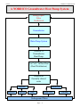
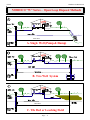
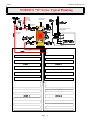
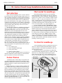
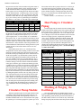
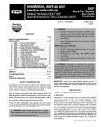
Installation
Manual
NORDIC® models Wec-45-55-65-80-175
Revision 5.0
February 00
Liquid-to-Water
Geothermal Heat Pumps
Table of Contents
Water Well Requirements .....
3
Groundloop design..............
13
Refrigerant Circuit HACW
24
Optimum Placement .......................
5
Circulator pumps ………....
15
Electrical Requirements ...........
25
Plumbing the Heat Pump ................
5
Loop Flushing & antifreeze......
17
Performance Charts ...........
26
Safety Controls ..............................
7
Engineering Data ................
19
Trouble Shooting Guide ..............
31
Starting the Heat Pump ...................
10
General Specifications ............... 21
Electrical Diagrams .....................
34
Maintenance ..................................
11
W Series features …………. ..
Warranty ...................................
36
22
METRIC VERSION
Water Well or Groundloop Operation
Maritime Geothermal Ltd.
P.O. Box 413
Petitcodiac, N.B.
E0A 2H0
Email: [email protected]
www.discribe.ca/nordic
Feb-00
Maritime Geothermal Ltd.
A NORDIC® Groundwater Heat Pump System
Energy Input:
Solar
Geothermal
Groundwater
Water Pump System
NORDIC®
Groundwater
Heat Pump
Fan Coils / Infloor Heat
(Heat Distribution)
Disposal of
thermally altered
water
Surface
Irrigation
Domestic
Subsurface
Pond/
Return Well
Underground Water
Page .... 2
Leaching
Maritime Geothermal Ltd.
Feb-00
NORDIC® Liquid-to-Water System Prerequisites
There are five specific parts or sub-systems to a groundwater heat pump installation:
The source of energy (groundwater)
Water Well
The method of supplying energy to the heat pump
Water Pump System
Converting the energy to a useable form
Heat Pump
Distributing the heat
Infloor Heat / Fan Coil Units
Returning the exhaust water to the earth for reheating
Water disposal
Water Well Requirements
1.
2.
3.
4.
5.
A DRILLED well of 127 mm diameter or larger.
Well casing properly sealed or grouted into rock.
Water flow preferably entering well at a depth of 25m or
more.
Temperature of well at least 4.4°C. (Normally 7+ °C.)
Well must be able to supply requirements of BOTH heat
pump and residence usage at the same time with maximum drawdown from static level of 9 m.
The Heat Pump
A heat pump with Btu output capable of heating the
home in all winter weather conditions should be selected using a “rule of thumb” as follows:
Water Requirements For
Nordic® Heat Pumps
Model
Wec-45
Wec-55
Wec-65
Wec-80
Wec-175
Heat Pump
32 L/min
45 L/min
55 L/min
90 L/min
113 L/min
Home
14
14
14
14
14
Total
46
59
69
104
127
Note: These are minimum water requirements based on an
entering water temperature of 7° C.
Water Pump System
1.
2.
3.
4.
A submersible pump is generally required. Must be able
to pump the required water flow listed above at a minimum of 210 kPa at the dynamic pumping depth of your
well.
Make sure you select the pump using the pump manufacturers pump chart.
Use a minimum of 135 litre equivalent air bladder tank.
Make sure the pump will be able to pump the required
flow for the heat pump while maintaining 275 kPa on the
water lines for usage in the rest of the home.
Page .... 3
Model
Sq. M of Home*
Nordic Wec-45
Nordic Wec-55
Nordic Wec-65
Nordic Wec-80
Nordic Wec-175
160
250
325
500
700
*NOTE: Rule of thumb, use proper heat load software to
Maritime Geothermal Ltd. recommends that anyone considering the installation of a heat pump in their home or office
have a professional heat loss / load calculation prepared on
the building to determine the heating and cooling requirements. The correct sizing of the heat pump to the home can
only be properly accomplished with the use of specialized
software programs designed for this job.
Discharge Water Methods
1.
Although we highly recommend it, you do NOT necessarily have to have a return well.
2. Some of our customers do one of the following with their
return or waste water:
A. Run it into a drain or ditch.
B. Pond, river or stream.
C. Leaching field.
In most instances if you run the water right out on
top of the ground it will soak back into the ground in less than
15m of travel. If suitable care is taken to insure that the drain
pipe runs downhill and the end of the pipe is protected by a
bale of hay or spruce bows etc. the end of the pipe will not
freeze. When snow comes it will usually cover the entire
process much like a small spring.
The above information is intended to give the prospective
user/purchaser some insight as to the general requirements for
a successful application of the NORDIC® heat pump.
Feb-00
Maritime Geothermal Ltd.
NORDIC® “W” Series - Open Loop Disposal Methods
25 to 30 m
A. Single Well (Pump & Dump)
25 to 30 m
B. Two Well System
C
25 to 30 m
C. Tile Bed or Leaching Field
Page .... 4
Maritime Geothermal Ltd.
Feb-00
recommends the installation of a water flow meter on the discharge line so that the exact amount of water flowing can be
determined at a glance. Once the correct flow of water has
When the heat pump reaches it's destination it should
been established and determined to be consistent, the water
be unpacked to determine if any damage has occurred during
flow meter could be removed from the line.
shipment. Any visible damage should
NOTE: Installing unions at each end of the
be noted on the carrier's freight bill and
In to Heat Pump
meter and similar unions on a piece of pipe
a suitable claim filed at once.
of the same length, allows the user to insert
Brass fitting on
the meter in the line whenever the flow of
The heat pump is well conwater lines to
water
is to be checked and then remove the
structed and every effort has been made
heat Pump
meter
so that it does not deteriorate from day
to insure that it will arrive intact, howto
day
usage
ever it is in the customer's best interest
Plumbing lines, both supply and disto examine the unit thoroughly when it
Water (IN)
charge,
must
be of adequate size to handle
arrives.
and (OUT)
the water flow necessary for the heat pump.
lines
For distances less than 12 m from the pressure tank, 19 mm copper or plastic lines
3.2
mm
D
stem
Thershould be run while for longer distances we
The location of liquid-to water
mometers
&
Pressure
recommend that 25 mm plastic or copper
heat pump inside the home should be
gauges
attached
through
lines should be run to the heat exchanger.
determined by:
P/T
port.
Similarly, a 25 mm line should be run from
1. The ease at which piping runs
the discharge pipe to the method if disposal.
can be connected to the inInstall a P/T (Pete’s Plug) plug on the Wafloor heating headers on the
ter (IN) and Water (OUT) lines just outside the heat pump
output side of the unit.
so that it is easy to record the water in and out tempera2. Space availability in a mechanical room for the hot
tures and pressures accurately.
water distribution tank and associated pumps etc.
Ideally there will be water flow available in excess
3. Ease of access to the water well supply and discharge
of
the
requirement
of the heat pump. In such a situation the
lines or groundloop lines.
proper
pump
can
be
selected to maintain a pressure of 200
If possible the four main service doors should remain
to
275
kPa
on
the
lines
when the heat pump is operating.
clear of obstruction for a distance of (.6m) so that servicing
However in some cases a well can supply a heat pump only if
and general maintenance can be carried out with a minimum
the minimum requirement for water is used.
of difficulty. Raising the heat pump off the floor a few inches
is generally a good practice since this will prevent unnecesSupply water flow to the heat pump can be consary corrosion of the bottom panel of the unit.
Unpacking
Placement
We recommend that the heat pump be placed on a
piece of 50 mm Styrofoam covered with 6.5 mm plywood.
The Styrofoam will smooth out any irregularities in the cement floor while the plywood will distribute the weight of the
NORDIC® unit evenly over the Styrofoam. This process will
also deaden the compressor noise emitted from the bottom of
the cabinet.
As an alternative, several pieces of 50 mm x 100 mm
lumber can be placed under the unit running from the electrical connection side to the opposite side of the heat pump.
Laying the 50 mm x 100 mm lumber in this manner will give
the best support since they will be at right angles with the internal steel compressor and heat exchanger support.
Plumbing the Heat Pump
(water well application)
When installed on a water well, the NORDIC heat
pump must be supplied with an adequate water supply, since
in essence, water is the fuel for the unit. It is imperative that
the flow requirements listed in the engineering section be
closely adhered to.
When setting up the unit, Maritime Geothermal Ltd.
Page .... 5
Fittings and accessories available for P/T
plug application to heat pump.
Feb-00
Maritime Geothermal Ltd.
NORDIC® “W” Series Typical Plumbing
Boiler feed
pressure reducer set at
80 to 10 kPa
Pressure gauge
0 to 400 kPa
Thermometer
10 to 60°C
275 to
400 Ltr
Pressure relief valve set at
500 to 700 kPa
Minimum line
size 25 mm
Set at
49°C
Minimum line size 25 mm
Page .... 6
Maritime Geothermal Ltd.
Feb-00
trolled very accurately by the installation of a reverse action
pressure valve in the supply water discharge line of the unit.
If the unit is a heating / cooling unit then a dual high pressure / low pressure valve or a pair of valves must be installed
Another method of regulating the flow is by the use
of a “DOLE” valve. This valve will automatically control the
amount of water flowing through it by varying the diameter of
a flexible rubber orifice through which the water passes. If
either of such valves is needed they can be supplied and installed by your dealer.
All water line valves on both the supply and discharge lines should be either BALL or GATE valves since a
GLOBE valve will create too much restriction across the line
possibly causing the heat pump to trip out on it's low pressure
safety cutout control as a result of insufficient water flow.
Exposed water lines will have a tendency to sweat
when the heat pump is in operation, therefore it is recommended that both the water supply and discharge lines be insulated with suitable insulation.
Hot Water Connections
Connection to the hot water generator feature of the
heat pump is accomplished by teeing into an electric or oil
fired hot water tank with a capacity of 180 litre minimum. A
typical piping diagram is shown on page 11 in this manual.
Be sure to note the position of the check valve and the direction of water flow.
One should be sure the tank is filled with water and
is under pressure before activating the heat pump. Slightly
loosen the copper union on the hot water discharge pipe to
allow air to escape from the system before the unit is started.
This step will make certain that the water circulator is flooded
with water when it is started.
Since the pump is water lubricated, damage will occur to the
pump if it is run dry for even a short period.
The union on the discharge water line may have to be purged
of air several times before good circulation is obtained. A
hand placed several feet down the line will sense when the
water is flowing.
The thermostats on the hot water tank should be set to
49°C. since the heat pump has an internal thermostat set at a
low of 52°C. By setting the tank thermostats as described, the
heat pump will try to keep the tank above the cut-in point of
the electric element settings thus generating hot water from
the heat pump only. During summer, or periods of high demand, the electric elements will energize to help make hot
water.
NOTE: If (2) shut-off valves are located on the hot water
lines as shown in the diagram on page 11, be sure that the
valves are open when the heat pump is operating. If both
valves are closed when the heat pump is operating, water
will expand in the hot water heat exchanger and could
cause damage to the hot water circulator pump.
Water Disposal Methods
Page .... 7
Water disposal methods vary from area to area however some consideration should be made to prevent the cooled
discharge water from immediately coming in contact with the
supply source. Generally speaking, returning water to a
second well, pond lake or stream is acceptable while returning water to the same well will usually cool the water
so much that the heat pump will shut off on it's low pressure / temperature safety control.
A return well should be a minimum of 25 m from the
supply well for residential applications. The water returned to
the well will not be necessarily be pumped into the same aquifer, depending on underground conditions, but the return well
does have to be able to supply the same quantity of water as
the amount you wish to recharge into it.
If the static level (level when not being pumped) of a
well is high (3 to 6 m from the surface) it may be necessary to
place a watertight well cap on the well to keep the return water from flowing out the top of the well. This cap is commonly required since a certain amount of pressure is needed
to force the return water back down the well if the static level
is high.
Return wells are not always the answer and to some
it may be more satisfactory to pump the water to a pond or
away into the woods.
Water recharged naturally through percolation into the soil is
an alternative to a recharge well. The water discharged will
generally soak into the ground within a distance of 15 to 30 m
If care is taken to make sure the end of the pipe does not
freeze then this method of disposal works well.
Safety Controls
The NORDIC reversible W series heat pump has three built
in safety controls which are designed to protect the unit from
situations which could damage it.
A. LOW REFRIGERANT PRESSURE (heating mode)
The low refrigerant pressure control is designed to
shut the unit down if the refrigerant evaporating pressure becomes too low thus risking the danger of freezing conditions
in the evaporator.
There are only (4) reasons why this control would
activate and they are:
1. Low water flow. (See requirements for each model)
2. Low water temperature. (Below 4.5 °C)
3. Dirty or fouled heat exchanger.
4. Low refrigerant charge.
B. HIGH PRESSURE CONTROL
The second safety control is a high pressure safety limit
which monitors compressor discharge pressure. This device
will not normally trip unless there is an interruption in water
flow.
Such a situation could occur if the hot buffer tank circulator
pump failed or if the heat pump had an extremely dirty air
filter.
C. LOW SUCTION TEMPERATURE CONTROL (cooling
mode)
Feb-00
Maritime Geothermal Ltd.
NORDIC® W–Series Hot Water Production
Aquastat set
at 49°C max
0 to
690 kPa
Dole® flow regulating
valve 35 to 55 L/min.
10 mm Copper or
Plastic lines
Page .... 8
Maritime Geothermal Ltd.
Feb-00
NORDIC® W Series (2 fitting) Buffer Tank Piping
4°C to 70°C
Min 25 mm lines—Wec-45-65
Min 32 mm lines Wec-80
Min 38 mm lines Wec-175
IMPORTANT INSTRUCTIONS
1. Diagram above shows the proper manner for plumbing a tank that has only (2) ports.
2. The tank must have at least 38 mm fittings at “A” to accommodate the flow from the heat pump and the floor
circulator pump when both are in operation.
3. The water line between “A” on the tank and the “Tee” at “B” should be at least 38 mm.
4. Install a check valve at “C” and “D” to prevent back flow through the floor system or the heat pump when only
one of the two pumps is running.
5. The tank should have an additional 19 mm fitting at “M” to allow for an immersion (well style) probe thermostat.
This control works during the cooling mode to shut down
the compressor as in A above.
If one of these controls trips it will activate a
LOCK-OUT RELAY which prevents the unit from restarting until power to the control circuit is broken (by turning the
thermostat to the OFF position and then back on again) or the
electrical supply to the unit is broken by opening the heat
pump breaker and then closing it again. If one of these controls trips there is a serious problem with the system and it
must be rectified if the unit is to maintain good service.
NOTE: Under no circumstances should the heat pump
lock-out relay be reset more than twice in an hour. If the
heat pump is shutting off because of LOW or NO water
flow then repeated resetting of the unit could cause the
heat exchanger to freeze and rupture destroying the heat
pump.
Page .... 9
Electrical Connections
The NORDIC unit is supplied with an opening for 19 mm
conduit nipple on the right side of the unit. An additional
knockout (13 mm) is provided to facilitate connection of an
external circulator pump to the set of dry contacts provided.
Above this is another 9.5 mm hole for the thermostat wire. A
wiring diagram is located inside the electrical box cover for
quick reference and although the connections to be made are
quite simple, Maritime Geothermal Ltd. recommends that a
properly qualified electrician be retained to make the connections and wire the thermostat.
The NORDIC unit may be supplied with a thermostat and
connections are clearly marked on the control box. Using a 3conductor (18 gauge) wire suitable for the job, connect the
terminals in the heat pump electrical box to the corresponding
terminals on the thermostat.
Feb-00
Maritime Geothermal Ltd.
Starting the Heat Pump
BEFORE starting the heat pump the following areas
should be rechecked to assure proper operation.
1. Check all high voltage field wiring and electrical connections inside the control box for good connection.
2. Check all low voltage thermostat to make sure they are
connected properly. Place thermostat HEAT-OFF-COOL
switch in the OFF position.
3. Turn on the main power switch. Allow the power to remain
ON without starting the unit for a period of 4 hours. Refrigerant migrates to the compressor oil when the compressor is
unheated. On most units a crankcase heater is standard equipment on your heat pump and it will warm the compressor,
dispelling the liquid refrigerant. Compressor damage can occur if the heat pump has been brought in from a cold location
and immediately started up.
4. Turn on the water supply and check all plumbing for leaks.
5. Check all buffer tanks and the domestic hot water tank to
be sure it is filled with water before energizing the circuit.
NOTE: The hot water tank should be energized for at least 4
hours before the heat pump is started. A combination of low
condenser temperature water and 7º C. water in the hot water
tank may cause the unit to shut down on it's low pressure control. If this happens close ONE valve in the hot water circuit
to temporarily shut off the flow to the domestic hot water generator. Do not shut off both valves since water expanding in
the hot water generator loop may cause damage to the circulator pump housing. When the hot buffer tank has come up to
temperature open the valve for normal hot water operation.
Slightly open the union on the hot water discharge
pipes to make sure that all air is out of the system and the circulator pump is flooded with water.
6. Make sure all pumps are wired, purged of air and ready to
pump water.
7. Vacuum out any dust and debris that may have collected in
the unit during installation.
8. Make sure the unit is sitting level.
9. Make sure the proper time-delay fuse has been installed in
the fuse box.
10. Have the following tools on hand and know how to use
them.
•
•
•
•
A refrigeration gauge set.
An electronic or other accurate thermometer
An amprobe.
A water flow meter.
11. Connect your refrigeration gauge set.
12. After the 4 hour warm-up period place the thermostat
function switch in the HEAT position, turn up the thermostat.
The compressor, main heat exchanger circulators and domestic hot water circulator will start.
NOTE: If the unit is equipped with an electric TACO water
valve the valve will open in 30 to 60 seconds followed by the
compressor. When the TACO water valve is fully open, an
internal switch activates the compressor circuit.
13. Observe the readings on the high and low pressure gauge
set. With entering water temperature of 7° to 10°C, the suction pressure (blue gauge) should be approximately 365 to
400 kPa while the head or discharge pressure (red gauge)
should be in the area of 1550 to 1900 kPa Depending on the
condenser side water flow and temperature. Record this information on the warranty test card.
14. Using an electronic thermometer or other accurate thermometer, record the supply water temp. ''IN'' and the water
temperature ``OUT''.
The outlet water temperature should be from 2.2° to 4°C.
cooler than the inlet water temperature.
15. Record the supply water flow in gpm.
16. Record the condenser (HOT) water flow through the machine. At 45 Lpm. You will see a 4°C to 5.5°C rise through
the heat exchanger.
17. Record the voltage at the terminal blocks with a digital
voltmeter.
18. At the electrical disconnect switch place the amprobe jaws
around the supply wires and record the current in each.
19. Place the thermostat function selector in the COOL position and turn down the stat to a temperature that will cause
water chilling to begin. When the aquastat selector switch is
set in the COOL mode the reversing valve will be energized.
Service Tools
Dole flow control Valve
Refrigeration Gauges
Amprobe
Digital Thermometer
In-line Flowmeter
Page .... 10
The Dole® flow control is a simple, selfcleaning device designed to deliver a constant volume of water from any outlet
whether the pressure is 100 kPa or as high as
860 kPa. The controlling mechanism consists of a flexible orifice that varies it’s area
inversely with pressure so that a constant
flow is maintained.
Maritime Geothermal Ltd.
Feb-00
General Maintenance
As with any piece of equipment there will eventually be some
maintenance to be done on the heat pump.
Maritime Geothermal recommends that a qualified serviceman be retained to carry out this procedure since the solution
involved is highly corrosive.
Reversible NORDIC® heat pumps are equipped with coaxial
type heat exchangers. These heat exchangers are not manually
cleanable however they can be cleaned with a sulfamic acid
solution commonly marketed under the trade name "IronOut". If you suspect that the water being pumped through
the unit is of a poor quality or you notice a decrease in performance after several years of use it may be necessary to
have the liquid heat exchanger cleaned.
Open Well & Hot Water Tank Plumbing Diagram
W Series Liquid-to-Water Heat Pumps
NOTE:
Check (IN) and (OUT)
Labels on your heat pump.
Design changes can cause
piping arrangement to differ from those shown at
left.
Follow the labeling on
your unit
49°C
Page .... 11
Feb-00
Maritime Geothermal Ltd.
Diagram A.
Design # 2
Design # 1
Diagram A.
Shown above are several of the many possible horizontal loop layouts which have been successfully employed in various types of ground conditions.
Design # 1
Shown is a typical reverse return header system and 2 parallel loops. On a 2 ton system each of these loops would be 150m long
with 1.3m spacing between the “U” sections, 3m spacing between the loops and buried 1.8m underground.
Design # 2 is a single loop of 32 to 38 mm diameter pipe with a length of 150m x the tonnage of the system and buried to a
depth of 1.8m underground. Individual runs of pipe should be kept a minimum of 3m apart.
Diagram B.
25 – 90m
Design # 3
Design # 4
3m min.
Design # 3.
Shown is a vertical borehole reverse-return header system. Vertical systems generally require 40 to 55m of borehole per ton of
heat pump for successful heat transfer to take place with the earth. Boreholes should be spaced a minimum of 3m apart while if
land is available, 8m spacing will produce better results.
Boreholes should be tremie grouted from bottom to top with bentonite or a mixture of bentonite and neat cement for proper conduction with the earth.
Design # 4.
Shown here is a typical series loop design using 32 to 38 mm pipe for the loops. Some designs incorporate a double “U” tube assembly down the well which allows for better heat transfer between the earth and the loop.
NOTE
Many other loop designs are in common use throughout North America. For a more comprehensive manual on earthloop design
refer to our Earthloop Design Manual or contact IGSHPA (International Ground Source Heat Pump Association) and request
their earth systems dealer training manual.
Page .... 12
Maritime Geothermal Ltd.
Feb-00
W- Series Closed Loop Installation Information
Horizontal Groundloops
Introduction
Many commercial buildings select a vertical or horizontal closed loop as the earth heat exchanger either because of a
lack of available groundwater or for the reduced maintenance
costs which can be obtained when compared to open loop systems. Often the problems which occur in a geothermal system are associated with the wells, pumps, or the direct result
of utilizing poor quality water or water which is contaminated
with sand or other foreign materials. Such contamination can
cause premature failure with pumps, water valves, heat exchangers and return wells.
To reduce these problems to a minimum a closed secondary heat exchange system is constructed with Type 3408
Polyethylene Plastic Pipe specifically engineered for the job.
Materials such as PVC and polybutylene are not recommended since their underground joining process is not as reliable as the fusion process used with type 3408 polyethylene.
The earthloop heat exchanger can consist of a single long
length of plastic commonly called a series style heat exchanger or more commonly is found as a number of parallel
loops connected to a reverse return header system. The series system for homes or light commercial applications up to
10 tons normally is constructed with 32 to 51 mm diameter
pipe while the parallel system uses multiple branch loops
from 19 to 25 mm connected to a larger header pipe system of
32 to 38 mm diameter. The parallel system offers several advantages such as:
• Less expensive pipe.
• Easier to handle the smaller pipe.
• Lower pressure drop
• Smaller circulator pump(s)
Of course on larger commercial systems it would not be
unusual to find header systems with up to 152 mm diameter
pipe for fluid flow into and out of the building.
Horizontal groundloop systems are most commonly
used where land is readily available since they are cheaper to
construct than their vertical counterparts. Although many configurations are available, we have found that a parallel system
with one (1) 150m “U” pipe per ton placed in a 76m x 1.3m
wide x 1.8m deep trench is easy to construct and provides
ample ground impact area to adequately supply a 0°C or better Entering Fluid Temperature to the heat pump even in the
most severe winter months. (See opposite Diagram A.)
Several companies including “Thermalworks” and the
International Ground Source Heat Pump Association (igshpa)
provide modeling software to size the heat pump to the home
and then size the loop to the demand of the home and heat
pump. Consideration is given to many factors such as type of
ground, moisture content and configuration of loops desired.
It is often possible to shorten loop lengths and resulting costs
when using some of the newer “Slinky” designs of earthloops. A comprehensive manual dedicated entirely to the installation of groundloops is available from Maritime Geothermal Ltd. which describes in detail the techniques involved in
installing a closed loop system.
Vertical Groundloops
Vertical groundloop systems are generally the system of
choice for commercial and institutional buildings since the
land area available is often limited to parking lots with some
adjacent landscaped areas.
Boreholes of 100 to 152 mm diameter are drilled with
conventional drilling equipment usually to a depth of less than
90m Each “ton” of heat pump installed requires approximately 46m of borehole. The 19 to 25 mm plastic pipe “U”
tubes are fused together using socket fusion techniques and
Horizontal
Groundloop
Socket Fusion
Mechanical joints or metal fittings of any kind are not
acceptable underground in an earth loop system due to large
temperature fluctuations which may loosen and break clamps
and the possibility of eventual corrosion perforation in couplings and “T’s”.
Fittings and joints are socket or butt fused together into
one contiguous unit using a technique developed by the gas
industry. A heater tool with the appropriate faces heats both
the pipe and fitting for a prescribed period of time and then
the two pieces are quickly removed from the heater, inserted
together and held in place until the joint cools. When properly
done the resulting joint is stronger than the original pipe with
no chance of leaks or breaks. For more information on butt
and socket fusion techniques see our website at (http://www.
discribe.ca/nordic/fusion.htm) or request a copy of the Central Tools Butt and Socket fusion manual.
Page .... 13
2 Well
System
Vertical
Boreholes
Feb-00
Maritime Geothermal Ltd.
18.2 m
Type 3408 PE tubing.
3
1.3
Excavated trenches minimum
1.3 m wide x 1.8 m deep.
NOTE: Trenches will be backfilled with material which will
maximize the thermal conductivity of the adjacent earth.
Each loop consists of 150 m
of 19 mm type 3408 PE 1100
kPa (SDR 11) geothermal
heat pump polyethylene tubing.
76 m
Allow a minimum of 3 m between each trench and preferably 5 to 6 meters if space
is available
19 mm “T’s”
Header
Detail
32 mm
header pipe
Insulate all tubing within 3 m of the structure
with 13 mm closed cell insulation.
Piping that is laid in a header trench should
be insulated to a point where each loop
branches to it’s individual trench.
Loop 4 shown above could be left uninsulated to pick up heat in the header trench as
long as the header trench is more than 3 m
out from the building.
18 m
Manifolding is normally done outside the
building using suitable fusion tools.
12 m
Page .... 14
Maritime Geothermal Ltd.
Feb-00
then pressure tested for leaks at 690 kPa using either water or
air. Provision should be made to allow enough extra pipe to
extend from the boreholes to the proposed location of the
header system. Prior to inserting down the hole the assembly
must be filled with water so that buoyancy will be at a minimum when inserting the “U” tube. Cap the ends so that mud
and debris cannot enter the loops during insertion and grouting. A piece of heavy rebar or galvanized pipe is attached to
the bottom 3 to 5 m of the “U” tube with tape to add weight
Table 1. Antifreeze Percentages by Volume
Protection down to:
-12°C
-9.5°C
-7°C
-4°C
Methanol
25%
21%
16%
10%
Propylene Glycol
38%
30%
22%
15%
to the assembly and also prevent it from curling up and gouging into the side of the borehole during insertion. The entire
length of the assembly should be taped every 3 m to create
greater rigidity in the “U” tube assembly as it is installed in
the borehole. The “U” tube is inserted into the borehole along
with the tremie pipe and the borehole is tremie grouted from
bottom to within 3 m of the top with a mixture of neat cement
and bentonite or 100% bentonite. When using bentonite refer
to the manufacturers instructions for mixing and select a product that provides a total solids content of from 25 to 30%
when mixed.
Horizontal trenches from 1.3 to 1.8m deep are dug
alongside the boreholes to the building so that a reverse return
(first pipe out on the supply line is the last pipe back on the
return line) header pipe arrangement can be constructed to tie
all the loops together. Lay out the header system so that air
cannot be easily trapped in the header using a technique approved by IGSPHA or the local governing authority. Use a
shovel to break away any ground between the trench and the
boreholes and dig a relief no less than 30 times the diameter
of the pipe to allow the pipe to bend to the header pipe without kinking. Be very careful not to disturb the original ground
under the relief so that you do not have to worry about the
pipe being kinked through compaction of the earth under the
pipe after the trench is backfilled. Fuse the individual smaller
loops to the main header loops and extend these into the home
by drilling through the concrete wall or by rising up the outside of the basement wall or slab and entering the structural
part of the home or building above grade. Any piping that
comes within 3 m of the structure should be insulated with 10
to 13 mm closed cell armaflex insulation to prevent freezing
from occurring near any structural part of the building. Likewise, all piping inside the building must be insulated to prevent condensation and subsequent dripping onto floors or
walls.
Circulator Pump Module
When the groundloop has been brought inside the home
or building to the location of the heat pump it must be connected to the pump module which generally consists of (1)
Grundfoss® Model UPS 26-99 or Taco® Model 0011 pump
for systems up to 3 ton and (2) pumps for systems up to 5 ton.
These units must be able to pump at least 9.5 to 12 l/min. per
ton of heat pump for proper operation of the system. To calculate the size of pumps required use the pressure drop tables
for the diameter and type of tubing used along with all elbows, T’s etc and the pressure drop through the unit’s heat
exchanger to arrive at:
( total ft of head) x (12 l/min./ton) x (No. of tons)
Heat Pump to Circulator
Piping
The heat pump must be connected to the circulator pump
module with a lineset suitable for the flow required with minimum pressure drop. Common line sizes would be 19 mm rubber or plastic for heat pumps from 1 to 2.5 ton while for unit
sizes 3 through 5 ton, 25 mm lines should be used. The installation of P/T plugs (pressure / temperature) pronounced
“Pete’s plugs” should be installed on both the entering and
leaving lines at the heat pump. The P/T plug will allow the
installer or homeowner to check water flow through the loop
by measuring the pressure difference through the heat exchanger and comparing this pressure drop to that of the appropriate model in the engineering section. (see Pressure Drop
vs. Water Flow Table)
Table 2. Litres of fluid per 30 meters of pipe
Type of Pipe
Diameter
Volume
(Litres)
Copper
25 mm
15.5
32 mm
24.2
38 mm
34.8
Rubber Hose
25 mm
14.8
Polyethylene
19 mm IPS SDR11
10.6
25 mm IPS SDR11
17.0
32 mm IPS SDR11
32.2
38 mm IPS SDR11
41.3
51 mm IPS SDR11
71.5
Heat Exchanger
Average
6.0
Flush Cart Tank
381 mm x .9 m
high
10.8
Flushing & Purging the
Earthloop
Once the earthloop has been installed and all connections are completed to the heat pump and pumping station the
entire plumbing system should be pressure tested with air to
690 kPa to make sure there are no leaks on any of the inside
fittings. Soap all joints and observe that the pressure remains
Page .... 15
Page .... 16
LEGEND:
1. 19 mm copper “T”
1a. 19 mm Type “L” copper pipe
2. 19 mm copper union.
3. 19 to 32 mm Copper to female adaptor.
4. 32 mm galv. nipple or threaded pipe.
5. 32 mm galv. 90° elbow.
6. –20°C to 60°C thermometer (19 mm MPT)
7. 32 x 32 x 13 mm galv. “T”
8. Automatic air vent ( 6 mm MPT)
9. 19 x 6 mm reducing bushing.
10. 500 kPa pressure relief valve (19 mm MPT)
11. 19 mm galv. “T”
12. 19 mm galv nipple.
13. 32 x 32 x 19 mm galv. “T”
14. 32 mm full port ball valve.
15. Taco® 0011 or Grundfos UP-26-99 pump.
16. 25 mm Barbed adaptor to 25 mm MPT.
17. 25 mm full port ball valve.
18. 25 mm galv. Nillpe or threaded pipe.
19. 32 mm x 32 x 25 mm galv. “T”
20. 1o Litre expansion tank.
21. 0 to 200 kPa gauge (6 mm MPT)
22. 32 mm PE 3408 to brass MPT transition adaptor.
23. 32 mm PE 3408 90° elbow.
24. 32 mm PE 3408 Plastic earthloop pipe.
32 mm Galv. lines
32 mm lines from
flush cart.
Feb-00
Maritime Geothermal Ltd.
Maritime Geothermal Ltd.
Feb-00
constant for 1 hour.
NOTE: If you use pressure gauges permanently installed
on the system as in the case of a demonstration situation etc.
be careful not to exceed the maximum pressure rating of the
gauges to avoid damage to their mechanism.
When satisfied all connections are leak free, release the
air pressure and connect a flush cart (see diagram) to the
flushing access ports at the pump station. A temporary flushing system can alternately be constructed
using a 170 litre barrel and a pump with
Typical
sufficient volume and head capability to
Flush
circulate fluid at a velocity of at least 1
Cart
cm/sec. through all parts of the loop. Begin pumping water through the earthloop
making sure that the intake of the pump
stays submerged at all times by continuously adding water from a hose etc. Water
flowing back on the return line should be
directed below the water level in the barrel
or flush tank to prevent air being mixed
with the outgoing water. Once the lines
have been filled and no more air bubbles
are appearing in the line, adjust the flow
valves to circulate water through the heat
pump using the same technique as described above. When all air is removed
reverse the flow of water through the lines
by interchanging the flush cart lines and
purge again. You will be able to visibly
tell when all air is removed.
Installing
Antifreeze
In most mid and northern areas of the US and in all of
Canada it is necessary to condition the loop fluid by the addition of some type of antifreeze solution so that it will not
freeze during operation in the winter months. This antifreeze
is required because the loop fluid will normally reach a low
entering temperature of –2.2°C to 0°C. and refrigerant temperatures inside the heat pump’s heat exchanger may be as
low as 11°C cooler. See the antifreeze concentration chart at
left for details of freeze protection afforded under different
concentrations.
NOTE: Add enough antifreeze to allow for a temperature 11°C lower than the expected lowest loop fluid
temperature entering the heat pump.
NOTE: Although many different antifreeze solutions
have been employed in geothermal systems, the alcohols such
as methanol or ethanol have the most desirable characteristics
for earthloop application. The overall heat transfer characteristics of these fluids remain high although care must be taken
when handling pure alcohols since they are extremely flammable. Once mixed in a typical 25% by volume ratio with water the solution is not flammable. In situations where alcohols
are not allowed as a loop fluid due to local regulations then
propylene glycol is a non-toxic alternative which can be substituted . Propylene glycol should only be used in cases where
alcohols are not permitted since the heat transfer characteristics are less desirable and it becomes more viscous at low
temperatures which increases pumping watts. The volume of
fluid that your loop system holds can be closely estimated by
totaling the number of ft. of each size pipe in the system and
referencing Table 2. the for approximate volume per 30 meters.
When the volume of the loop has been calculated and
the appropriate amount of antifreeze is
ready for addition by referencing Table
1. , drain the equivalent amount of water
from the flush cart or mixing barrel and
replace it with the antifreeze. When using
alcohols be sure to inject it below the water line to reduce initial volatility of the
pure antifreeze. If the loop is large and
the tank is small it may be necessary to
refill the tank with antifreeze several
times to get all the antifreeze into the
loop. Pump the loop for 5 to 10 minutes
longer to insure the remaining fluid has
been well mixed.
Initial
Pressurization
At this point open all valves in the flow
circuit and slowly close off the supply
and return flush cart valves in a manner
that leaves about 175-300 kPa on the
system. If an air bladder expansion tank
is used the bladder should be charged to the above pressure
before actual water pressure is put on the system . Systems
employing a commercially available loop pump kit that do not
have an expansion tank, thermometers and pressure gauges
will experience a greater fluctuation of pressure in the loop
between winter and summer. This fluctuation is normal since
expansion and contraction of the loop fluid must be handled
by the elasticity of the plastic loop. Pressurize the loop to a
pressure of 300 kPa when installing a system in the fall going
into the heating season. If installing in spring or summer
charge to 175 kPa.
After operating the machine for a period of time, any
residual air in the system can be bled off through valved vertical standpipes in the pump module. If pressure drops below
175 kPa add additional water / antifreeze mix with the purge
pump to bring the pressure back to the original setting.
Page .... 17
Feb-00
Maritime Geothermal Ltd.
1.8 m
19 mm type 3408 Plastic
laid in each corner
3m
1.3 m
3m
IMPORTANT NOTES:
Horizontal style pipe runs should be placed 1.8 m deep a minimum of 1.3 m wide trench as shown
above. Hand backfilling in the area just over the plastic is recommended to prevent crushing or pinching the pipe during backfilling operations. Individual trenches (1 per ton) should be spaced a minimum of 3 m apart to allow the best performance of the ground field.
Insulate all inside piping with
Armaflex
closed cell insulation 10
mm minimum
thickness.
Insulate all lines within 3 m of the
foundation with 10 mm armaflex.
Page .... 18
Maritime Geothermal Ltd.
Feb-00
32 mm
32 mm
Page .... 19
Feb-00
Maritime Geothermal Ltd.
Typical 3-4 and 5 Loop Parallel Header Design
160 m loops
32 x 19 x 19 mm tee
32 x 32 x 19 mm tee
32 mm 90°
19 mm 90°
19 mm tees
1m
32 mm SDR 11 Type 3408 PE pipe
Page .... 20
Maritime Geothermal Ltd.
Feb-00
NORDIC® Series Wec-45-55-65-80-175
Engineering and Performance Data
June 1998
Page .... 21
Feb-00
Maritime Geothermal Ltd.
Revision 4.0
Color: Caissie Grey
Models: W-45-55-65
Style: Vertical
Maritime Geothermal Ltd.
Liquid-to-Water Heat Pumps
Date: June 1998
Drawn By: G. Kaye
Title: Cabinet Layout
76 mm
76 mm
710 mm
815 mm
76 mm
76 mm
100 mm
280 mm
660 mm
100 mm
76 mm
64 mm
General Specifications
1.
2.
3.
4.
5.
6.
7.
8.
Case constructed of satin galvanized materials with epoxy latex enamel finish.
Type 316 copper brazed plate heat exchangers on both source and sink sides.
High Efficiency scroll or reciprocating heat pump compressor.
Liquid receiver and suction line accumulator .
Four removable doors and a removable top for easy access from any side
Acoustically insulated cabinet.
Optional domestic hot water heat exchanger.
All Copper piping throughout the heat pump.
Page .... 22
Maritime Geothermal Ltd.
Feb-00
Maritime Geothermal Ltd.
Liquid-to-Water Heat Pumps
Date: June 1998
•
Supply water (IN)
Thermostatic expansion valves.
•
High efficiency
scroll compressors.
•
Supply water
(OUT)
•
Suction accumulator.
•
Baked enamel cabinet with satin galvanized condensate
tray and floor.
Components accessible from all four
sides.
Heavy duty electrical
components.
Hard start kit on all
models single phase
models.
•
•
Style: Horizontal
Title: Component & Piping Layout
Galvanized metal
with baked enamel
or epoxy based finish.
•
•
•
Models: W-45-55-65
Condenser
•
Color: Caissie Grey
Domestic Hot Water
(IN)
Domestic Hot Water
(OUT)
Evaporator
•
Drawn By: G. Kaye
Revision 4.0
•
Double wall potable
water desuperheater.
•
Hot Water circulator
•
High Efficiency brazed
plate heat exchangers.
•
Reversing Valve
•
Liquid line filter drier.
•
HOT water (OUT)
•
Sight glass.
•
Liquid receiver.
•
•
HOT water (IN)
Insulated water coils.
•
High & Low access
ports.
Remote reset lockout relay system.
(Front) Plumbing side
•
•
Acoustically insulated
cabinet.
•
Cabinet spot welded
together for superior
strength.
High efficiency scroll
compressor.
•
•
(Back) Electrical Box Side
Page .... 23
Functions: Heating, Cooling & Domestic Hot Water
HOT
Water
OUT
Cool Water
IN
Compressor
Accumulator
Connect to common
suction line
Bulb
Bulb
Plate
Eaporator
Desuperheater
Rev. Valve
De-energized
Heating Mode
Plate
Condenser
CK Valve
Filter
Receiver
TXV
Equalizer Tube
Cold
Water
OUT
Warm
Water
IN
Maritime Geothermal Ltd.
Drawn By: Glenn Kaye
Maritime Geothermal Ltd.
Feb-00
Water Flow Requirements in Litres/min (Condenser (HOT) Side)
(LWT)°C - (EWT)°C
Wec-45 (35,000 Btu’s)
Wec-55 (50,000 Btu’s)
Wec-65 (60,000 Btu’s)
13.9°C
10.45 (l/min)
15 (l/min.)
18.2 (l/min.)
11.1
13.2
19.1
22.7
8.3
17.7
25.5
30.5
5.55°C
26.4
37.7
45.5
2.8
52.7
75.5
91
1.7
88.2
126
151.4
NOTE: When selecting circulator pump sizes for the condenser side of a heat pump for infloor heat use, it
is normal practice to limit the temperature rise to 5.6°C or less for the highest output temperature vs. refrigerant discharge pressure.
Equation
Btu Output (Btu’s/hr) = (L/min) x (2.2 lbs./litre) x (60 min/hr) x (temp. diff. °C x 1.8)
Therefore for a W- 45 the temp rise across the heat exchanger would be:
Igpm =
(Btu/hr Output)
=
35,000
= 35,000 = 26.51 L/min.
(°C temp. diff. x 1.8) x (2.2 lbs./gal.) x (60 min/hr)
(10 x 2.2 x 60)
1320
Divide the BTU output of any water heat pump by 1320 yields the flow required at a temperature rise of
5.55°C form entering water temp (EWT) to leaving water temp (LWT).
Electrical Supply and Thermostat Wire Sizes @ 380v/3/50
Model
Wec-45
Wec-55
Wec-65
BTU output @ W10°C/W50°C
35m (10.3 kw)
50m (15.4 kw)
60m (17.7 kw)
9
11
13
22
33
# 14-4
# 14-4
# 14-4
# 10-4
# 6-4
Max. Fuse Size ( Delay)
15
20
20
30
50
Max. breaker size
15
20
20
30
50
# 18
# 18
# 18
#18
#18
4
4
4
4
4
Min. circuit ampacity
Minimum wire size
Thermostat wire size
Thermostat conductors
Wec-80
Wec-175
100m (30 kw) 150m (44 kw)
Brazed Plate Heat Exchanger —Water Flow Vs. Pressure drop Tables (kPa)
(L/min)
Wec-45 (CB50-30)
Wec-55
53
42 (kPa)
26.6
16.1
45.4
31
19.9
11.9
37.9
22.1
14.1
8.5
30.3
14.5
9.2
5.5
22.7
8.4
5.3
3.17
15.1
3.7
2.4
1.44
Page .... 25
(CB50-38)
Wec-65
(CB50-50)
Feb-00
Maritime Geothermal Ltd.
Nominal 3 ton
W-45ec-HAC
Source Data
ELT °F Evap. °F Flow Igpm
Power Consumption
LLT °F Temp. Diff °F HAB (Btu's)
°C
°C
L/min
°C
°C
tons
27
15
8.0
23.2
3.79
18,204
-2.8
-9.4
36
-4.9
2.1
1.5
33
20
8.0
28.7
4.28
20,556
0.6
-6.7
36
-1.8
2.4
1.7
39
25
8.0
34.2
4.81
23,084
3.9
-3.9
36
1.2
2.7
1.9
45
30
8.0
39.6
5.37
25,793
7.2
-1.1
36
4.2
3.0
2.1
51
35
8.0
45.0
5.98
28,688
10.6
1.7
36
7.2
3.3
2.4
57
40
8.0
50.4
6.62
31,773
13.9
4.4
36
10.2
3.7
2.6
63
45
8.0
55.7
7.30
35,056
17.2
7.2
36
13.2
4.1
2.9
69
50
8.0
61.0
8.03
38,539
20.6
10.0
36
16.1
4.5
3.2
Watts
Amps
Output
(Btu's)
Sink Data
KW OUT
COP
tons
2,707
5.0
27,441
8.0
2.97
2.3
2,687
5.0
29,727
8.7
3.24
2.5
2,667
4.9
32,187
9.4
3.54
2.7
2,647
4.9
34,828
2,628
4.9
37,658
10.2
3.85
11.0
4.20
2.9
3.1
2,611
4.9
40,685
11.9
4.57
3.4
2,596
4.8
43,916
12.9
4.96
3.7
2,584
4.8
47,359
13.9
5.37
3.9
ZR40K3-TFD
380
Source Data
EWT °F
Igpm
LWT °F
Delta °F
Cond. °F
°C
L/min
°C
°C
°C
105
8.0
110.7
5.7
120
40.6
36
43.7
3.2
48.9
105
8.0
111.2
6.2
120
40.6
36
44.0
3.4
48.9
105
8.0
111.7
6.7
120
40.6
36
44.3
3.7
48.9
105
8.0
112.3
7.3
120
40.6
36
44.6
4.0
48.9
105
8.0
112.8
7.8
120
40.6
36
44.9
4.4
48.9
105
8.0
113.5
8.5
120
40.6
36
45.3
4.7
48.9
105
8.0
114.1
9.1
120
40.6
36
45.6
5.1
48.9
105
8.0
114.9
9.9
120
40.6
36
46.0
5.5
48.9
50
Nominal 3 ton
W-45ec-HAC
ELT °F Evap. °F Flow Igpm
Heating
3phase
Cooling
Power Consumption
LLT °F Temp. Diff °F HAB (Btu's)
°C
°C
L/min
°C
°C
tons
52
40
8.0
43.9
8.09
38,826
11.1
4.4
36
6.6
4.5
3.2
52
40
8.0
44.1
7.91
37,987
11.1
4.4
36
6.7
4.4
3.2
52
40
8.0
44.3
7.74
37,138
11.1
4.4
36
6.8
4.3
3.1
52
40
8.0
44.4
7.56
36,276
11.1
4.4
36
6.9
4.2
3.0
52
40
8.0
44.6
7.38
35,403
11.1
4.4
36
7.0
4.1
3.0
52
40
8.0
44.8
7.19
34,516
11.1
4.4
36
7.1
4.0
2.9
52
40
8.0
45.0
7.00
33,616
11.1
4.4
36
7.2
3.9
2.8
52
40
8.0
45.2
6.81
32,702
11.1
4.4
36
7.3
3.8
2.7
Watts
Amps
Output
(Btu's)
1,577
3.6
44,208
Sink Data
KW OUT
EER
13.0
24.62
tons
3.7
1,682
3.7
43,728
12.8
22.58
3.6
1,793
3.9
43,256
12.7
20.72
3.6
1,909
4.0
42,792
12.5
19.00
3.6
2,033
4.1
42,340
12.4
17.42
3.5
2,164
4.3
41,902
12.3
15.95
3.5
2,304
4.5
41,478
12.2
14.59
3.5
2,452
4.7
41,072
12.0
13.34
3.4
ZR40K3-TFD
Page .... 26
Model
380
50
EWT °F
Igpm
°C
L/min
65
8.0
18.3
36
70
LWT °F
Delta °F
Cond. °F
°C
°C
°C
74.2
9.2
80
23.5
5.1
26.7
8.0
79.1
9.1
85
21.1
36
26.2
5.1
29.4
75
8.0
84.0
9.0
90
23.9
36
28.9
5.0
32.2
80
8.0
88.9
8.9
95
26.7
36
31.6
5.0
35.0
85
8.0
93.8
8.8
100
29.4
36
34.3
4.9
37.8
90
8.0
98.7
8.7
105
32.2
36
37.1
4.8
40.6
95
8.0
103.6
8.6
110
35.0
36
39.8
4.8
43.3
100
8.0
108.6
8.6
115
37.8
36
42.5
4.8
46.1
3phase
Model
Maritime Geothermal Ltd.
Feb-00
Nominal 4 ton
W-55ec-HAC
Source Data
ELT °F Evap. °F Flow Igpm
Power Consumption
LLT °F Temp. Diff °F HAB (Btu's)
°C
°C
L/min
°C
°C
tons
27
15
10.0
22.8
4.20
25,208
-2.8
-9.4
45
-5.1
2.3
2.1
33
20
10.0
28.2
4.77
28,645
0.6
-6.7
45
-2.1
2.7
2.4
39
25
10.0
33.6
5.39
32,354
3.9
-3.9
45
0.9
3.0
2.7
45
30
10.0
38.9
6.06
36,336
7.2
-1.1
45
3.9
3.4
3.0
51
35
10.0
44.2
6.77
40,592
10.6
1.7
45
6.8
3.8
3.4
57
40
10.0
49.5
7.52
45,124
13.9
4.4
45
9.7
4.2
3.8
63
45
10.0
54.7
8.32
49,935
17.2
7.2
45
12.6
4.6
4.2
69
50
10.0
59.8
9.17
55,027
20.6
10.0
45
15.5
5.1
4.6
Watts
Amps
Output
(Btu's)
Sink Data
KW OUT
COP
tons
3,754
6.7
38,021
11.1
2.97
3.2
3,727
6.7
41,364
12.1
3.25
3.4
3,700
6.6
44,983
13.2
3.56
3.7
3,675
6.6
48,880
3,652
6.6
53,057
14.3
3.90
15.5
4.26
4.1
4.4
3,631
6.5
57,518
16.9
4.64
4.8
3,612
6.5
62,264
18.2
5.05
5.2
3,595
6.5
67,297
19.7
5.48
5.6
ZR57K3-TFD
380
Source Data
EWT °F
Igpm
LWT °F
Delta °F
Cond. °F
°C
L/min
°C
°C
°C
105
10.0
111.3
6.3
120
40.6
45
44.1
3.5
48.9
105
10.0
111.9
6.9
120
40.6
45
44.4
3.8
48.9
105
10.0
112.5
7.5
120
40.6
45
44.7
4.2
48.9
105
10.0
113.1
8.1
120
40.6
45
45.1
4.5
48.9
105
10.0
113.8
8.8
120
40.6
45
45.5
4.9
48.9
105
10.0
114.6
9.6
120
40.6
45
45.9
5.3
48.9
105
10.0
115.4
10.4
120
40.6
45
46.3
5.8
48.9
105
10.0
116.2
11.2
120
40.6
45
46.8
6.2
48.9
50
Nominal 4 ton
W-55ec-HAC
ELT °F Evap. °F Flow Igpm
Heating
3phase
Cooling
Power Consumption
LLT °F Temp. Diff °F HAB (Btu's)
°C
°C
L/min
°C
°C
tons
52
40
10.0
42.7
9.26
55,537
11.1
4.4
45
6.0
5.1
4.6
52
40
10.0
43.0
9.04
54,243
11.1
4.4
45
6.1
5.0
4.5
52
40
10.0
43.2
8.83
52,962
11.1
4.4
45
6.2
4.9
4.4
52
40
10.0
43.4
8.61
51,685
11.1
4.4
45
6.3
4.8
4.3
52
40
10.0
43.6
8.40
50,406
11.1
4.4
45
6.4
4.7
4.2
52
40
10.0
43.8
8.19
49,118
11.1
4.4
45
6.6
4.5
4.1
52
40
10.0
44.0
7.97
47,813
11.1
4.4
45
6.7
4.4
4.0
52
40
10.0
44.3
7.75
46,484
11.1
4.4
45
6.8
4.3
3.9
Watts
Amps
Output
(Btu's)
2,172
4.6
62,950
Sink Data
KW OUT
EER
18.4
25.57
tons
5.2
2,325
4.8
62,180
18.2
23.33
5.2
2,483
5.0
61,437
18.0
21.33
5.1
2,648
5.2
60,722
17.8
19.52
5.1
2,820
5.4
60,032
17.6
17.87
5.0
3,003
5.7
59,368
17.4
16.35
4.9
3,198
5.9
58,729
17.2
14.95
4.9
3,407
6.2
58,112
17.0
13.64
4.8
ZR57K3-TFD
Page .... 27
Model
380
50
EWT °F
Igpm
°C
L/min
65
10.0
18.3
45
70
LWT °F
Delta °F
Cond. °F
°C
°C
°C
75.5
10.5
80
24.2
5.8
26.7
10.0
80.4
10.4
85
21.1
45
26.9
5.8
29.4
75
10.0
85.2
10.2
90
23.9
45
29.6
5.7
32.2
80
10.0
90.1
10.1
95
26.7
45
32.3
5.6
35.0
85
10.0
95.0
10.0
100
29.4
45
35.0
5.6
37.8
90
10.0
99.9
9.9
105
32.2
45
37.7
5.5
40.6
95
10.0
104.8
9.8
110
35.0
45
40.4
5.4
43.3
100
10.0
109.7
9.7
115
37.8
45
43.2
5.4
46.1
3phase
Model
Feb-00
Maritime Geothermal Ltd.
Nominal 5 ton
W-65ec-HAC
Source Data
ELT °F Evap. °F Flow Igpm
Power Consumption
LLT °F Temp. Diff °F HAB (Btu's)
°C
°C
L/min
°C
°C
tons
27
15
12.0
22.6
4.38
31,564
-2.8
-9.4
54
-5.2
2.4
2.6
33
20
12.0
28.1
4.92
35,435
0.6
-6.7
54
-2.2
2.7
3.0
39
25
12.0
33.5
5.50
39,586
3.9
-3.9
54
0.8
3.1
3.3
45
30
12.0
38.9
6.12
44,039
7.2
-1.1
54
3.8
3.4
3.7
51
35
12.0
44.2
6.78
48,820
10.6
1.7
54
6.8
3.8
4.1
57
40
12.0
49.5
7.49
53,951
13.9
4.4
54
9.7
4.2
4.5
63
45
12.0
54.7
8.26
59,456
17.2
7.2
54
12.6
4.6
5.0
69
50
12.0
59.9
9.08
65,360
20.6
10.0
54
15.5
5.0
5.4
Watts
Amps
Output
(Btu's)
Sink Data
KW OUT
COP
tons
4,430
7.8
46,682
13.7
3.09
3.9
4,415
7.8
50,505
14.8
3.35
4.2
4,405
7.8
54,622
16.0
3.63
4.6
4,400
7.8
59,056
4,398
7.8
63,832
17.3
3.93
18.7
4.25
4.9
5.3
4,401
7.8
68,973
20.2
4.59
5.7
4,409
7.8
74,503
21.8
4.95
6.2
4,420
7.8
80,446
23.6
5.33
6.7
ZR68KC-TFD
380
Source Data
EWT °F
Igpm
LWT °F
Delta °F
Cond. °F
°C
L/min
°C
°C
°C
105
12.0
111.5
6.5
120
40.6
54
44.2
3.6
48.9
105
12.0
112.0
7.0
120
40.6
54
44.5
3.9
48.9
105
12.0
112.6
7.6
120
40.6
54
44.8
4.2
48.9
105
12.0
113.2
8.2
120
40.6
54
45.1
4.6
48.9
105
12.0
113.9
8.9
120
40.6
54
45.5
4.9
48.9
105
12.0
114.6
9.6
120
40.6
54
45.9
5.3
48.9
105
12.0
115.3
10.3
120
40.6
54
46.3
5.7
48.9
105
12.0
116.2
11.2
120
40.6
54
46.8
6.2
48.9
50
Nominal 5 ton
W-65ec-HAC
ELT °F Evap. °F Flow Igpm
Heating
3phase
Cooling
Power Consumption
LLT °F Temp. Diff °F HAB (Btu's)
°C
°C
L/min
°C
°C
tons
52
40
12.0
42.9
9.08
65,389
11.1
4.4
54
6.1
5.0
5.4
52
40
12.0
43.1
8.88
63,910
11.1
4.4
54
6.2
4.9
5.3
52
40
12.0
43.3
8.68
62,478
11.1
4.4
54
6.3
4.8
5.2
52
40
12.0
43.5
8.48
61,076
11.1
4.4
54
6.4
4.7
5.1
52
40
12.0
43.7
8.29
59,689
11.1
4.4
54
6.5
4.6
5.0
52
40
12.0
43.9
8.10
58,300
11.1
4.4
54
6.6
4.5
4.9
52
40
12.0
44.1
7.90
56,891
11.1
4.4
54
6.7
4.4
4.7
52
40
12.0
44.3
7.70
55,447
11.1
4.4
54
6.8
4.3
4.6
Watts
Amps
Output
(Btu's)
2,778
5.7
74,869
Sink Data
KW OUT
EER
21.9
23.54
tons
6.2
2,928
5.9
73,904
21.7
21.82
6.2
3,093
6.1
73,035
21.4
20.20
6.1
3,272
6.3
72,245
21.2
18.66
6.0
3,466
6.6
71,520
21.0
17.22
6.0
3,676
6.8
70,845
20.8
15.86
5.9
3,901
7.1
70,206
20.6
14.58
5.9
4,143
7.5
69,587
20.4
13.38
5.8
ZR68KC-TFD
Page .... 28
Model
380
50
EWT °F
Igpm
°C
L/min
65
12.0
18.3
54
70
LWT °F
Delta °F
Cond. °F
°C
°C
°C
75.4
10.4
80
24.1
5.8
26.7
12.0
80.3
10.3
85
21.1
54
26.8
5.7
29.4
75
12.0
85.1
10.1
90
23.9
54
29.5
5.6
32.2
80
12.0
90.0
10.0
95
26.7
54
32.2
5.6
35.0
85
12.0
94.9
9.9
100
29.4
54
35.0
5.5
37.8
90
12.0
99.8
9.8
105
32.2
54
37.7
5.5
40.6
95
12.0
104.8
9.8
110
35.0
54
40.4
5.4
43.3
100
12.0
109.7
9.7
115
37.8
54
43.1
5.4
46.1
3phase
Model
Maritime Geothermal Ltd.
Feb-00
Nominal 8 ton
W-80ec-HAC
Source Data
ELT °F Evap. °F Flow Igpm
Power Consumption
LLT °F Temp. Diff °F HAB (Btu's)
°C
°C
L/min
°C
°C
tons
27
15
20.0
22.8
4.20
50,399
-2.8
-9.4
90
-5.1
2.3
4.2
33
20
20.0
28.3
4.72
56,664
0.6
-6.7
90
-2.1
2.6
4.7
39
25
20.0
33.7
5.28
63,347
3.9
-3.9
90
1.0
2.9
5.3
45
30
20.0
39.1
5.87
70,496
7.2
-1.1
90
4.0
3.3
5.9
51
35
20.0
44.5
6.51
78,160
10.6
1.7
90
6.9
3.6
6.5
57
40
20.0
49.8
7.20
86,389
13.9
4.4
90
9.9
4.0
7.2
63
45
20.0
55.1
7.94
95,232
17.2
7.2
90
12.8
4.4
7.9
69
50
20.0
60.3
8.73
104,736
20.6
10.0
90
15.7
4.8
8.7
Watts
Amps
Output
(Btu's)
Sink Data
KW OUT
COP
tons
7,051
13.3
74,465
21.8
3.09
6.2
7,074
13.3
80,807
23.7
3.35
6.7
7,086
13.3
87,530
25.6
3.62
7.3
7,088
13.3
94,688
7,084
13.3
102,339
27.7
3.91
30.0
4.23
7.9
8.5
7,075
13.3
110,538
32.4
4.58
9.2
7,064
13.3
119,340
35.0
4.95
9.9
7,052
13.3
128,803
37.7
5.35
10.7
ZR11M3-TWD
400
Source Data
EWT °F
Igpm
LWT °F
Delta °F
Cond. °F
°C
L/min
°C
°C
°C
105
20.0
111.2
6.2
120
40.6
90
44.0
3.4
48.9
105
20.0
111.7
6.7
120
40.6
90
44.3
3.7
48.9
105
20.0
112.3
7.3
120
40.6
90
44.6
4.1
48.9
105
20.0
112.9
7.9
120
40.6
90
44.9
4.4
48.9
105
20.0
113.5
8.5
120
40.6
90
45.3
4.7
48.9
105
20.0
114.2
9.2
120
40.6
90
45.7
5.1
48.9
105
20.0
114.9
9.9
120
40.6
90
46.1
5.5
48.9
105
20.0
115.7
10.7
120
40.6
90
46.5
6.0
48.9
Delta °F
Cond. °F
50
Nominal 8 ton
W-80ec-HAC
ELT °F Evap. °F Flow Igpm
Heating
3phase
Cooling
Power Consumption
LLT °F Temp. Diff °F HAB (Btu's)
°C
°C
L/min
°C
°C
tons
52
40
20.0
43.3
8.74
104,823
11.1
4.4
90
6.3
4.9
8.7
52
40
20.0
43.4
8.56
102,756
11.1
4.4
90
6.4
4.8
8.6
52
40
20.0
43.6
8.38
100,611
11.1
4.4
90
6.5
4.7
8.4
52
40
20.0
43.8
8.20
98,394
11.1
4.4
90
6.6
4.6
8.2
52
40
20.0
44.0
8.01
96,109
11.1
4.4
90
6.7
4.4
8.0
52
40
20.0
44.2
7.81
93,762
11.1
4.4
90
6.8
4.3
7.8
52
40
20.0
44.4
7.61
91,356
11.1
4.4
90
6.9
4.2
7.6
52
40
20.0
44.6
7.41
88,897
11.1
4.4
90
7.0
4.1
7.4
Watts
Amps
Output
(Btu's)
4,444
10.5
119,993
Sink Data
KW OUT
EER
35.2
23.59
tons
10.0
4,703
10.7
118,808
34.8
21.85
9.9
4,981
11.0
117,613
34.5
20.20
9.8
5,279
11.3
116,412
34.1
18.64
9.7
5,597
11.6
115,212
33.8
17.17
9.6
5,935
12.0
114,019
33.4
15.80
9.5
6,294
12.4
112,838
33.1
14.51
9.4
6,674
12.8
111,676
32.7
13.32
9.3
ZR11M3-TWD
Page .... 29
400
50
EWT °F
Igpm
LWT °F
°C
L/min
°C
°C
°C
65
20.0
75.0
10.0
80
18.3
90
23.9
5.6
26.7
70
20.0
79.9
9.9
85
21.1
90
26.6
5.5
29.4
75
20.0
84.8
9.8
90
23.9
90
29.3
5.4
32.2
80
20.0
89.7
9.7
95
26.7
90
32.1
5.4
35.0
85
20.0
94.6
9.6
100
29.4
90
34.8
5.3
37.8
90
20.0
99.5
9.5
105
32.2
90
37.5
5.3
40.6
95
20.0
104.4
9.4
110
35.0
90
40.2
5.2
43.3
100
20.0
109.3
9.3
115
37.8
90
42.9
5.2
46.1
3phase
Feb-00
Maritime Geothermal Ltd.
Nominal 12 ton
W-175ec-HAC
Source Data
ELT °F Evap. °F Flow Igpm
Power Consumption
LLT °F Temp. Diff °F HAB (Btu's)
°C
°C
L/min
°C
°C
tons
27
15
25.0
22.2
4.75
71,290
-2.8
-9.4
113
-5.4
2.6
5.9
33
20
25.0
27.6
5.37
80,508
0.6
-6.7
113
-2.4
3.0
6.7
39
25
25.0
33.0
6.01
90,219
3.9
-3.9
113
0.5
3.3
7.5
45
30
25.0
38.3
6.70
100,504
7.2
-1.1
113
3.5
3.7
8.4
47
35
25.0
39.6
7.43
111,447
8.3
1.7
113
4.2
4.1
9.3
52
40
25.0
43.8
8.21
123,130
11.1
4.4
113
6.6
4.6
10.3
57
45
25.0
48.0
9.04
135,638
13.9
7.2
113
8.9
5.0
11.3
62
50
25.0
52.1
9.94
149,052
16.7
10.0
113
11.1
5.5
12.4
Watts
Amps
Output
(Btu's)
Sink Data
KW OUT
COP
tons
9,922
15.8
105,154
30.8
3.11
8.8
9,968
15.8
114,528
33.6
3.37
9.5
9,996
15.8
124,334
36.4
3.64
10.4
10,010
15.8
134,668
10,014
15.8
145,626
39.5
3.94
42.7
11.13
11.2
12.1
10,013
15.8
157,303
46.1
12.30
13.1
10,008
15.8
169,795
49.7
13.55
14.1
10,004
15.8
183,197
53.7
14.90
15.3
ZR16M3-TWD
400
Source Data
EWT °F
Igpm
LWT °F
Delta °F
Cond. °F
°C
L/min
°C
°C
°C
105
25.0
112.0
7.0
120
40.6
113
44.5
3.9
48.9
105
25.0
112.6
7.6
120
40.6
113
44.8
4.2
48.9
105
25.0
113.3
8.3
120
40.6
113
45.2
4.6
48.9
105
25.0
114.0
9.0
120
40.6
113
45.5
5.0
48.9
105
25.0
114.7
9.7
120
40.6
113
45.9
5.4
48.9
105
25.0
115.5
10.5
120
40.6
113
46.4
5.8
48.9
105
25.0
116.3
11.3
120
40.6
113
46.8
6.3
48.9
105
25.0
117.2
12.2
120
40.6
113
47.3
6.8
48.9
Delta °F
Cond. °F
50
Nominal 12 ton
W-175ec-HAC
ELT °F Evap. °F Flow Igpm
Heating
3phase
Cooling
Power Consumption
LLT °F Temp. Diff °F HAB (Btu's)
°C
°C
L/min
°C
°C
tons
52
40
25.0
42.1
9.88
148,144
11.1
4.4
113
5.6
5.5
12.3
52
40
25.0
42.3
9.69
145,300
11.1
4.4
113
5.7
5.4
12.1
52
40
25.0
42.5
9.49
142,397
11.1
4.4
113
5.8
5.3
11.9
52
40
25.0
42.7
9.29
139,422
11.1
4.4
113
5.9
5.2
11.6
52
40
25.0
42.9
9.09
136,368
11.1
4.4
113
6.1
5.1
11.4
52
40
25.0
43.1
8.88
133,222
11.1
4.4
113
6.2
4.9
11.1
52
40
25.0
43.3
8.66
129,974
11.1
4.4
113
6.3
4.8
10.8
52
40
25.0
43.6
8.44
126,613
11.1
4.4
113
6.4
4.7
10.6
Watts
Amps
Output
(Btu's)
6,709
12.1
171,043
Sink Data
KW OUT
EER
50.1
22.08
tons
14.3
6,996
12.4
169,178
49.6
20.77
14.1
7,318
12.8
167,373
49.0
19.46
13.9
7,675
13.2
165,619
48.5
18.16
13.8
8,069
13.6
163,907
48.0
16.90
13.7
8,499
14.1
162,228
47.5
15.68
13.5
8,966
14.6
160,574
47.0
14.50
13.4
9,470
15.2
158,935
46.6
13.37
13.2
ZR16M3-TWD
Page .... 30
400
50
EWT °F
Igpm
LWT °F
°C
L/min
°C
°C
°C
65
25.0
76.4
11.4
80
18.3
113
24.7
6.3
26.7
70
25.0
81.3
11.3
85
21.1
113
27.4
6.3
29.4
75
25.0
86.2
11.2
90
23.9
113
30.1
6.2
32.2
80
25.0
91.0
11.0
95
26.7
113
32.8
6.1
35.0
85
25.0
95.9
10.9
100
29.4
113
35.5
6.1
37.8
90
25.0
100.8
10.8
105
32.2
113
38.2
6.0
40.6
95
25.0
105.7
10.7
110
35.0
113
40.9
5.9
43.3
100
25.0
110.6
10.6
115
37.8
113
43.7
5.9
46.1
3phase
Maritime Geothermal Ltd.
Feb-00
NORDIC® W-Series Trouble Shooting Guide
Fault
Possible Cause
Verification
Recommended Action
Electric circuit test shows no voltage on the line side of compressor
contactor.
Check for blown fuse at heat
pump’s disconnect box or blown
fuse
Disconnect switch open
Voltmeter shows no voltage on the
line side of the compressor contactor.
Determine why the disconnect
switch was opened, if all is OK
close the switch.
Fuse blown
At heat pump disconnect box, volt- Replace fuse with proper size and
meter shows voltage on the line
type. (Time-delay) type “D”
side but not on the load side.
Check total load on system.
Low voltage
Voltmeter shows abnormally low
Call power company.
voltage (Below 210 v) at heat pump
disconnect switch.
Burned out motor
Ohmmeter shows no resistance between common and run terminals
or between common and start terminals. Note: Be sure compressor
overload has had a chance to reset.
If comp. is hot this may take several hours.
Thermal overload on compressor tripped.
Ohmmeter shows reading when
If windings are open or overload is
placed across R and S terminals and faulty, replace compressor.
infinity between C & R or C & S.
Make sure the internal overload has
had time to reset.
Faulty compressor contactor.
Voltage on line side with contactor Replace contactor.
held closed, but no voltage on one
or both terminals on the load side.
Points pitted or burned.
Seized compressor due to
locked or damaged mechanism.
Compressor attempts to start but
trips it’s internal overload after a
few seconds.
Attempt to “rock” compressor free.
If normal operation cannot be established, replace compressor.
Faulty run capacitor.
Check with ohmmeter for shorts,
open etc.
Replace if faulty.
Power Failure
COMPRESSOR
Compressor not operating
Page .... 31
Determine cause and replace motor.
Feb-00
Maritime Geothermal Ltd.
Fault
Possible Cause
Verification
(cont)
Compressor
not operating
Open control circuit. •
Thermostat not calling for heat.
High or low pressure limit open.
Lock-out relay energized.
Locate open control and determine cause.
Replace faulty control if necessary.
Normal operation except too frequent
starting and stopping.
Check for loose wiring.
Check differential setting on aquastat.
Widen setting to allow longer run cycles.
Check for continuity through internal
overload in compressor.
Observe suction & discharge pressures –
make sure amp draw is within range.
•
•
Compressor Intermittent contact
“short cycles” in electrical control
circuit.
Compressor overloaded.
HEATING
MODE
Unit trips off
on “LOW”
suction pressure control.
Unit trips off
on “HIGH”
pres. control.
Recommended Action
Low or no evaporator Manually open water valve (if equipped) Check well pump or circ. pump for proper
water flow.
and measure water flow with a flowmeter. operation. Check water valve for proper
operation.
Evaporator water
supply too cold.
Measure temperature of water. Check
flow rate with spec. sheet to determine if
proper gpm is available.
Increase flow to proper gpm for temperature of water used.
Faulty low pressure
ctrl.
Refrigerant pressure control should open
on drop at approx. 310 kPa for well operation and 240 kPa
for closed loop application.
The low control should reset automatically
when refrigerant pressure reaches 450 to
485 kPa. Heat pump can then be restarted
by resetting the lock-out relay. (Turn
power off then back on) Replace faulty
control if it will not reset.
Low refrigerant
charge.
Check water temp. and flow. Clean heat
exchanger. If suction is still low check
suction gas pres. Normal suction is 345415 (380 typical) on R-22 or R-407C
Add refrigerant slowly until sight glass
clears. Install fluorescent dye and check
for possible leaks with ultra violet light,
halide leak detector etc..
Low or no condensing water flow.
TXV stuck closed
Filter drier plugged.
Check condenser flow with flowmeter.
Check for refrigerant flow through TXV
and filter.
Check circulator pump operation. Check
operation of condenser refrigerant water
flow valve.
Replace filter or TXV if required.
Page .... 32
Maritime Geothermal Ltd.
Feb-00
Fault
Possible Cause
COOLING
MODE
Low “temperature
sensor” opens.
Low or no water flow on
evaporator side.
(Note: The function of the two
heat exchangers are reversed
when in cooling mode. Evap.
Becomes cond. / cond. Becomes evaporator.)
Check fluid flow, strainers, pumps
and valves in the system. Temp. ctrl.
will open in about 1 minute if water
flow is interrupted or if unit is run
with suction pressure below 345 kPa.
Aquastat on cold buffer tank
set too low. Should be 6.1 –
7.2°C
Verify accuracy of aquastat with reli- Replace or readjust aquastat for
able hand held thermometer.
proper operation.
High Pressure
limit opens.
Domestic Hot
Water Storage
Tank
not maintaining at
least 49°C.
Recommended Action
Restore proper flow and temperature. Reset lock-out relay. Replace low suction temp. thermostat.
Low water flow on condenser Check flow of well water or loop wa- Restore flow and reset lock-out
side
ter.
relay.
Check for air or strainer restrictions.
Water valves open.
TXV possibly not opening.
Liquid line possibly plugged.
DOMESTIC
HOT WATER
Insufficient hot
water.
Verification
Warm bulb with hand and observe
suction pressure while operating.
Circulator pump not operating. Use an amprobe to measure current
draw.
Replace TXV or filter-drier id
non operational or plugged.
Replace if faulty.
Blockage or restriction in the
water line or hot water heat
exchanger.
Check water flow and power to
Remove obstruction in water
pump. Check water lines for obstruc- lines. Acid treat the domestic hot
tion
water coil.
Thermostat limit is open.
Check contact operation. Should
close at 49°C and open at 57°C.
Disconnect switch open, or
Check both line and load sides of
fuse blown in electrical supply fuses. If switch is open determine
to hot water tank.
why.
Replace thermostat if faulty.
Replace blown fuse or breaker or
close switch.
Reset button tripped on hot
water tank.
Check voltage at elements with mul- Push reset button.
timeter.
Thermostat on hot water tank
set too low. Should be set at
49°C.
Visually inspect the setting.
Heat pump not running enough Note the amount of time the heat
hours to make sufficient hot
pump runs in any given hour.
water.
Page .... 33
Readjust the setting to 49°C.
Temporarily turn up the tank thermostats until colder weather creates longer run cycles.
Feb-00
Maritime Geothermal Ltd.
Revision 4.3
EC Model
Models: Wec-45-175
380 / 3 / 50
Maritime Geothermal Ltd.
Liquid-to-Liquid Heat Pumps
Date: June 1998
Drawn By: G. Kaye
Page .... 34
Title: Schematic Diagram
Maritime Geothermal Ltd.
Feb-00
Maritime Geothermal Ltd.
Liquid-to-Liquid Heat Pumps
Date: June 1998
Drawn By: G.Kaye
Page .... 35
Revision 4.3
EC Model
Models: W-45-55-65
380 / 3 / 50
Title: Electrical Box Connections
Feb-00
Maritime Geothermal Ltd.
LIMITED WARRANTY
MARITIME GEOTHERMAL LTD. warrants that the heat pumps manufactured
by it shall be free from defects in materials and workmanship for a period of (1)
ONE YEAR after the date of installation or for a period of (1) ONE YEAR AND
(60) SIXTY DAYS after the date of shipment, whichever occurs first. In addition
MARITIME GEOTHERMAL LTD. warrants that the compressor shall be free of
defects in materials and workmanship for an additional period of (48) FORTYEIGHT MONTHS from said date.
MARITIME GEOTHERMAL LTD. shall, at it's option repair or replace any part or
parts covered by this warranty which shall be returned to MARITIME GEOTHERMAL LTD., transportation charges prepaid, which, upon examination proves to be
defective in materials or workmanship. Replacement or repaired parts and components are warranted only for the remaining portion of the original warranty period.
This warranty is subject to the following conditions:
1.
The NORDIC® heat pump must be properly installed and maintained in accordance with MARITIME Geothermal LTD.'s installation and maintenance instruct
ions.
2.
The installer must complete the “Installation Data Sheet”, have it endorsed
by the owner and return it to Maritime Geothermal Ltd. within 21 days after the installation of the unit.
3. It is the responsibility of the building or general contractor to supply temporary
heat to the structure prior to occupancy. These heat pumps are designed to provide
heat only to the completely finished and insulated structure. Start-up of the unit shall
not be scheduled prior to completion of construction and final duct installation for
validation of this warranty.
4. It is the customer's responsibility to supply the proper quantity and quality of water.
If the heat pump, manufactured by MARITIME GEOTHERMAL LTD. fails to conform to this warranty, MARITIME GEOTHERMAL LTD. 's sole and exclusive liability shall be, at it's option, to repair or replace any part or component which is returned by the customer during the applicable warranty period set forth above, provided that (1) MARITIME Geothermal LTD. is promptly notified in writing upon
discovery by the customer that such part or component fails to conform to this warranty. (2) The customer returns such part or component to MARITIME GEOTHERMAL LTD., transportation charges prepaid, within (30) thirty days of failure, and (3)
MARITIME GEOTHERMAL LTD. 's examination of such component shall disclose to it's satisfaction that such part or component fails to meet this warranty and
the alleged defects were not caused by accident, misuse, neglect, alteration, improper installation, repair or improper testing.
Page .... 36