1
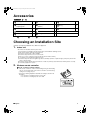
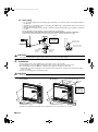
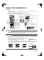
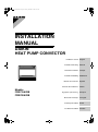
00_CV_3P257982-1.fm Page 1 Monday, December 7, 2009 1:41 PM
INSTALLATION
MANUAL
DAIKIN
HEAT PUMP CONVECTOR
Installation manual
Installationsanleitung
Deutsch
Manuel d’installation
Français
Installatiehandleiding
Manual de instalación
Manuale di installazione
Models
FWXV15AVEB
FWXV20AVEB
English
Εγχειρßδιο εγκατÜστασηò
Nederlands
Español
Italiano
ΕλληνικÜ
Manual de instalação
Portugues
Installasjonshåndbok
Norsk
Installationshandbok
Svenska
FWXV15AVEB, FWXV20AVEB
DAIKIN INDUSTRIES, LTD.
.
.
Shinri Sada
Manager Quality Control Department
Low Voltage 2006/95/EC
Electromagnetic Compatibility 2004/108/EC *
Umeda Center Bldg., 2-4-12, Nakazaki-Nishi,
Kita-ku, Osaka, 530-8323 Japan
2082543.0551-QUA/EMC
KEMA Quality B.V.
DAIKIN.TCF.025 C24/11-2009
3SB64418-9C.fm Page 1 Monday, December 7, 2009 10:55 AM
3SB64418-9C
01_EN_3P257982-1.fm Page 1 Friday, December 4, 2009 3:20 PM
Safety Precautions
• The precautions described herein are classified as WARNING and CAUTION. They both contain important
information regarding safety. Be sure to observe all precautions without fail.
• Meaning of WARNING and CAUTION notices
WARNING..............Failure to follow these instructions properly may result in personal injury or loss of life.
CAUTION...............Failure to observe these instructions properly may result in property damage or personal injury,
which may be serious depending on the circumstances.
• The safety marks shown in this manual have the following meanings:
Be sure to follow this instructions.
Be sure to establish an earth connection.
Never attempt.
• After completing installation, conduct a trial operation to check for faults and explain to the customer how to operate the unit and
take care of it with the aid of the operation manual.
WARNING
• Ask your dealer or qualified personnel to carry out installation work.
Do not attempt to install the unit yourself. Improper installation may result in water leakage, electric shocks or fire.
• Install the unit in accordance with the instructions in this installation manual.
Improper installation may result in water leakage, electric shocks or fire.
• Be sure to use only the specified accessories and parts for installation work.
Failure to use the specified parts may result in the unit falling, water leakage, electric shocks or fire.
• Install the unit on a foundation strong enough to withstand the weight of the unit.
A foundation of insufficient strength may result in the equipment falling and causing injury.
• Electrical work must be performed in accordance with relevant local and national regulations and with instructions
in this installation manual. Be sure to use a dedicated power supply circuit only.
Insufficiency of power circuit capacity and improper workmanship may result in electric shocks or fire.
• Use a cable of suitable length.
Do not use tapped wires or an extension lead, as this may cause overheating, electric shocks or fire.
• Make sure that all wiring is secured, the specified wires are used, and that there is no strain on the terminal
connections or wires.
Improper connections or securing of wires may result in abnormal heat build-up or fire.
• When wiring the power supply and connecting the wiring between the units, position the wires so that the control
box lid can be securely fastened.
Improper positioning of the control box lid may result in electric shocks, fire or over heating terminals.
• When connecting the unit to “altherma” or a hydro box, be sure to turn off the unit, “altherma”, and hydro box
before starting work.
This procedure involves connecting high-voltage wires. Performing it while devices are energized may result in electrical shock, fire, injury, or
death.
• Be sure to earth the unit.
Do not earth the unit to a utility pipe, lightning conductor or telephone earth lead. Imperfect earthing may result in electric shocks.
• Be sure to install an earth leakage breaker.
Failure to install an earth leakage breaker may result in electric shocks or fire.
CAUTION
• Do not install the unit at any place where there is a danger of flammable gas leakage.
In the event of a gas leakage, build-up of gas near the unit may cause a fire to break out.
• Do not install the unit in a location where it may come in contact with mineral oil, oil vapour or spray, or
corrosive gas, or where there are machines that generate electromagnetic radiation.
This will cause deterioration of the plastic parts, corrosion of the copper pipes and brazed parts, and malfunctioning of the control system.
• Do not install the unit where the air contains high levels of salt such as air near the ocean and where
voltage fluctuates a lot (e.g. in factories). Also vehicles or vessels.
• Do not install accessories on the casing directly.
Drilling holes in the casing may damage electrical wires and consequently cause fire.
• While following the instructions in this installation manual, install drain piping to ensure proper drainage and
insulate piping to prevent condensation.
Improper drain piping may result in indoor water leakage and property damage.
• Tighten the flare nut according to the specified method such as with a torque wrench.
If the flare nut is too tight, it may crack after prolonged use, causing water leakage.
• Never use water that does not satisfy EU drinking water quality standards. Do not use well water, either.
Otherwise, the tank may be corroded. (Domestic hot water quality must be according to EN directive 98/83 EC.)
• The temperature of the water that flows through the unit must always be maintained between 6°C and 60°C.
• Do not touch the aluminum fin.
Doing so may result in injury.
1
■English
01_EN_3P257982-1.fm Page 2 Friday, December 4, 2009 3:20 PM
Accessories
Indoor unit
A – N
A Mounting plate
1
F Remote controller holder
1
L Piping insulation
2
B Titanium apatite photocatalytic
air-purifying filter
2
G Dry battery AAA. LR03
(alkaline)
2
M O ring
4
C Drain hose
1
H Operation manual
1
N Connection pipe
2
D Insulation sheet
2
J Installation manual
1
E Wireless remote controller
1
K Binding band
1
* For L piping insulation, M O ring and N connection pipe details, see the valve kit installation manual.
Choosing an Installation Site
• Before choosing the installation site, obtain user approval.
1.
Indoor unit
• The indoor unit should be sited in a place where:
1) the restrictions on installation specified in the indoor unit installation drawings are met,
2) both air inlet and air outlet have clear paths met,
3) the unit is not in the path of direct sunlight,
4) the unit is away from the source of heat or steam,
5) there is no source of machine oil vapour (this may shorten indoor unit life),
6) cool (warm) air is circulated throughout the room,
7) the unit is away from electronic ignition type fluorescent lamps (inverter or rapid start type) as they may shorten the
remote controller range,
8) the unit is at least 1m away from any television or radio set (unit may cause interference with the picture or sound),
9) no laundry equipment is located.
2.
Wireless remote controller
■Checks on remote controller settings
• This remote controller is common to the heating/cooling use and heating
only use. Use the DIP switch on the remote controller to set the heating/
cooling use or heating only use.
• Refer to the following explanation and make the setting as shown in the
illustration.
• For customers of heating/cooling use: Set to H/C
• For customers of heating only use: Set to H/O
DIP switch
H/C
■English
H/O
2
01_EN_3P257982-1.fm Page 3 Friday, December 4, 2009 3:20 PM
Indoor Unit Installation Drawings
The indoor unit may be mounted in any of the three styles shown here.
Exposed
Half concealed
Concealed
A Mounting
plate
Molding
Floor Installation
Grid (field supply)
Wall Installation
Location for securing the installation panel.
64
(700)
(unit: mm)
150
26
134
230
(600)
140
250
0
21
574
644
35
0
16
35
Front grille
70mm or more
Air filter
50mm or more
from walls
B Titanium apatite photocatalytic
air-purifying filter (2)
Front panel
E Wireless remote
controller
Screws
(field supply: M3 × 20L)
3
50mm or more
from walls
Caulk pipe
hole gap
with putty.
F Remote controller
holder
■English
01_EN_3P257982-1.fm Page 4 Friday, December 4, 2009 3:20 PM
Installation Tips
1.
Removing and installing front panel
• Removal method
1) Slide until the 2 stoppers click into place.
2) Open the front panel forward and undo the string.
3) Remove the front panel.
• Installation method
1) Attach the front grille and front panel after pulling the string
around them.
2) Close the front panel and slide until the stoppers click outside.
2.
Removing and installing front grille
3 tabs
Front grille
Casing
• Removal method
1) Open the front panel.
2) Remove the 4 screws and remove the front grille while pulling
it forward (3 tabs).
• Installation method
Remove
front grille
1) Secure the front grille with the 4 installation screws (3 tabs).
2) Return the front panel to the original position.
Front panel
3.
How to set the different addresses
When two indoor units are installed in one room, the two
wireless remote controllers can be set for different addresses.
Remove 4 screws.
1) Remove the front grille.
2) Lift the sensor securing plate and remove the front metal plate cover.
3) Remove connectors 5P, 6P, and 7P.
4) Remove the electrical wiring box (1 screw).
5) Remove the thermistor.
6) Remove the side metal plate cover (7 tabs).
7) Cut the address jumper (JA) on the printed circuit board.
8) Cut the address jumper in the remote controller.
5) Thermistor
3) Connector 6P
JA
JA ADDRESS
EXIST
1
CUT
2
3) Connector 5P
Open the front panel.
Jumper
2) Sensor
securing
plate
3) Connector 7P
4) Remove 1 screw.
6) Side metal plate cover
2) Front metal plate cover
■English
Jumper ADDRESS
EXIST
1
CUT
2
4
01_EN_3P257982-1.fm Page 5 Friday, December 4, 2009 3:20 PM
Indoor Unit Installation (1)
Exposed installation
1.
Installing indoor unit
3 tabs
Front grille
Casing
Preparation
• Open the front panel, remove the 4 screws and dismount the
front grille while pulling it forward.
Remove
front grille
• Follow the procedure below when removing the slit portions.
Front panel
Remove 4 screws.
Open the front panel.
■ For moldings
• Remove the pillars. (Remove the slit portions on the bottom
frame using nippers.)
2) Upper casing
■ For side piping
• Remove the pillars.
1) Remove the 7 screws.
2) Remove the upper casing (2 tabs).
3) Remove the left and right casings (2 tabs on each side).
4) Remove the slit portions on the bottom frame and casings
using nippers.
5) Return by following the steps in reverse order (3 > 2 > 1).
For moldings
3) Side
casings
3) Side casings
Remove 7 screws.
Remove the pillar.
For side piping
Casing
Bottom frame
Casing
Remove the pillar.
Remove the pillar.
2.
Attaching the connection pipe
• For water piping details, see the valve kit installation manual.
3.
Connecting the drain hose and drain piping
3-1. Connecting the drain hose
Insert the supplied C drain hose
into the socket of the drain pan.
Fully insert the drain hose until it
adheres to a seal of the socket.
Drain pan
Seal
Drain pan
C Drain hose
Seal
C Drain hose
5
■English
01_EN_3P257982-1.fm Page 6 Friday, December 4, 2009 3:20 PM
3-2. Drain piping
1) Use commercial rigid polyvinyl chloride pipe (general VP 20 pipe, outer diameter 26mm, inner diameter 20mm) for
the drain pipe.
2) The drain hose (outer diameter 18mm at connecting end, 220mm long) is supplied with the indoor unit. Prepare the
drain pipe picture below position.
3) The drain pipe should be inclined downward so that water will flow smoothly without any accumulation. (Should not
be trap.)
4) Insert the drain hose to this depth so it won’t be pulled out of the drain pipe.
5) Insulate the indoor drain pipe with 10mm or more of insulation material to prevent condensation.
6) Remove the air filters and pour some water into the drain pan to check the water flows smoothly.
(unit: mm)
100
150
100
Insert drain hose
to this depth so
it won’t be pulled
out of drain pipe.
Must be no trap.
220
C Drain hose
Do not touch water.
50mm
or more
Reducer
Vinyl chloride
drain pipe
(VP-20)
Vinyl chloride
drain pipe
(VP-30)
CAUTION
• Use polyvinyl chloride adhesive agent for gluing. Failure to do so may cause water leakage.
4.
Installation
• Secure using 6 screws for floor installations. (Do not forget to secure to the rear wall.)
• For wall installations, secure the A mounting plate using 5 screws and the indoor unit using 4 screws.
• The mounting plate should be installed on a wall which can support the weight of the indoor unit.
1) Temporarily secure the mounting plate to the wall, make sure that the panel is completely level, and mark the boring
points on the wall.
2) Secure the mounting plate to the wall with screws.
CAUTION
• Firmly secure the unit to the wall so that a gap does not form between the back of the unit and the wall.
Floor installation
Wall installation
5 screws (M4 × 25L) (field supply)
A Mounting
plate
Casing
The mounting plate
should be installed
on a wall which can
support the weight
of the indoor unit.
Molding
6 screws (M4 × 25L) (field supply)
4 screws (M4 × 25L) (field supply)
3) Attach the front panel and front grille in their original positions once all connections are complete.
■English
6
01_EN_3P257982-1.fm Page 7 Friday, December 4, 2009 3:20 PM
Indoor Unit Installation (1)
5.
Wiring
•
1)
2)
3)
4)
5)
Lift the sensor securing plate, remove the front metal plate cover, and connect the branch wiring to the terminal block.
Strip wire ends (15mm).
Connect the power supply wire to the terminal block of main wiring box securely.
Connect the earth wires to the corresponding terminals.
Pull wires to make sure that they are securely latched up, then retain wires with wire retainer.
Make sure that the wires do not come in contact with the metal conduit for the heat exchanger.
Terminal block
Shape wires so
that the front
metal plate cover
will fit securely.
Electrical component box
1
2
3
Firmly fix the wires with the
terminal screws.
Firmly secure wire
retainer so that
wires sustain no
external stress.
Connect
the Faston
terminal
here.
1
2
Wire retainer
H05RN
3
Use 0.75mm2 wires.
Earth wire
Power supply wire
Bundle the wires
with a twist tie and
carefully run the
wires so that the
wires will not come
in contact with the
copper pipe.
Make sure that the wires do not
come in contact with the metal
conduit for the heat exchanger.
Safety
breaker
To the sub electrical
wiring box
Power supply
50Hz 220-240V
60Hz 220V
Earth leakage
circuit breaker
Earth
From the sub electrical wiring box
WARNING
• Do not use tapped wires, stranded wires, extension cords, or starburst connections, as they may cause overheating,
electrical shock, or fire.
• Do not use locally purchased electrical parts inside the product. (Do not branch the power for the drain pump, etc.,
from the terminal block.) Doing so may cause electric shock or fire.
CAUTION
• Carefully run the wires connecting to the sub electrical wiring box so that the wires will not come in contact with the copper
pipe. If the wires come in contact with the copper pipe, water drops may enter the sub electrical wiring box and the unit may
malfunction.
• Be sure to connect the wires correctly. An incorrect connection may
damage components and make it impossible to operate or use the unit. Round crimp-style
terminal
• Use a round crimp-style terminal for connection to the power supply
Stranded Wire
terminal block. In case it cannot be used due to unavoidable reasons,
be sure to observe the following instruction.
• Place the round crimp-style terminals on the wires up to the covered part and secure in place.
• When connecting the wires to the terminal block, be sure to curl the wire ends as shown in the following illustration and
connect each wire to the corresponding terminal from the same direction. Furthermore, make sure that the right
dimensions of the wire ends stripping are kept.
[Dimensions of the
wire ends stripping]
20mm
<Good>
7
<Wrong>
10mm
<Wrong>
■English
01_EN_3P257982-1.fm Page 8 Friday, December 4, 2009 3:20 PM
6.
When connecting to a sub electrical wiring box
6-1. Procedure for connecting
main electrical wiring box
with sub electrical wiring box
[Figure 1]
From the main
electrical wiring
box
To the main electrical
wiring box
Along the wires to the ceiling.
1 2 3 4 5 6
1) Turn off the “altherma” and hydro box
Wires from the
before starting work.
electric actuator on
2) Remove the sub electrical wiring box
the two way valve
cover (with 2 tabs) after removing the
2P
screw and dismounting the sub
• H05RN
electrical wiring box from the bottom
4P
• Use 0.75mm2
frame of the unit (refer to Figure 2,
wires.
Sub electrical wiring box
Figure 3).
(field supply)
3) Connect the wires from the sub
electrical wiring box to Faston
X2M terminal block on the hydro box
1 4 67
terminals 1 and 2 on the terminal block
of the main electrical wiring box.
4) Connect wiring from the main electrical wiring box to sub electrical wiring box connectors 2P and 4P. Insert the
binding band previously attached to the wires into the sub electrical wiring box and secure the wires in place (refer
to Figure 1).
5) Insert the K binding band into the sub electrical wiring box (refer to Figure 4).
6) Replace the front metal plate cover and the sensor securing plate of the main electrical wiring box.
6-2. Procedure for connecting sub electrical wiring box with hydro box and two way valve
1) Connect the wires from the electric actuator on the two way valve to 1 and 2 on the terminal block of the sub
electrical wiring box (refer to Figure 1).
2) Connect X2M terminals 1 and 4 in the hydro box to terminals 5 and 6 in the sub electrical wiring box with the
specified wires. Similarly, connect X2M terminals 6 and 7 with sub electrical wiring box terminals 3 and 4 (refer to
Figure 1).
3) Fasten the two way valve and hydro box connecting wires with the K binding band and cut off any extra band
(refer to Figure 5).
4) Replace the sub electrical wiring box cover (refer to Figure 6).
5) Secure the sub electrical wiring box to the bottom frame (refer to Figure 6).
[Figure 2]
[Figure 3]
[Figure 4]
Screw
Tabs
[Figure 5]
K Binding band
[Figure 6]
Cut off any
extra band.
Fasten the 3 wires
securely together.
Leave some play in the 3 wires
between the terminal and the
(K)
K binding band so that no
force is exerted on the terminal.
Screw
Tabs
Exercising care so that
the wires are not caught
between the sub electrical
wiring box and the sub
electrical wiring box
cover, close the cover
until the 2 tabs latch
securely in the holes.
WARNING
• When connecting the unit to “altherma” or a hydro box, be sure to turn off the unit, “altherma”, and hydro box before starting
work. This procedure involves connecting high-voltage wires. Performing it while devices are energized may result in
electrical shock, fire, injury, or death.
■English
8
01_EN_3P257982-1.fm Page 9 Friday, December 4, 2009 3:20 PM
Indoor Unit Installation (1)
7.
Purging air
■Purging air
• Air pockets sometimes form in the piping during trial operation
after construction work and during normal operation. To
remove air pockets from inside the piping, follow the steps
below to purge air from the unit. Be sure to purge air while the
unit is in cooling or heating operation.
1) Remove the front panel and the air filter.
2) While pressing on the air purge valve with one hand, turn the
air purge valve knob with your other hand as shown.
3) Open the valve, make sure that air has been completely
purged, and then close the valve securely.
Knob
Air purge valve
Valve open
CAUTION
• There is a risk of injury if you touch the heat exchanger with your bare hand.
• Be sure to close the air purge valve after purging air.
Leaving the air purge valve open may result in water leakage and decreased performance.
• Before starting trial operation of the system, always check that the valve is closed.
• Water leakage will result if the knob of the air purge valve is loose. Check that the knob is tightly closed.
8.
DIP switch settings based on installation site conditions
Set DIP switch SW2-1 to heating/cooling use or heating only use based on the specifications of the outdoor unit.
• How to set and use the switch
Heating/cooling use or heating
only use selector DIP switch
Switch number
SW2-1
Set function
Set the DIP switch for heating/cooling use
or heating only use.
ON
ON (heating only use)
OFF
Use
Factory setting
OFF (heating/cooling use)
Select heating/cooling use or heating
only use.
OFF (heating/cooling use)
If the unit is being connected to “altherma” and the * part (see the example model) of the model number on the hydro box is
“BA” or later, set DIP switch SW2-2 to “ON”.
Example model: EKHBXE008BA3V3
*
DIP switch for control of the
interlink to “altherma”
9
• How to set and use the switch
Switch number
SW2-2
Set function
Controls interlink to “altherma”
ON
ON (Connect to a hydro box whose
* part of the model number is “BA” or later.)
OFF
OFF (Other)
Use
Connecting to a hydro box whose
* part of the model number is “BA” or later
Factory setting
OFF (Other)
■English
01_EN_3P257982-1.fm Page 10 Friday, December 4, 2009 3:20 PM
Indoor Unit Installation (2)
Half concealed installation
Only items peculiar to this installation method are given here. See exposed installation for additional instructions.
1.
Wall hole
670-690
(unit: mm)
• Drill a wall hole of the size shown in the illustration on the right.
Opening hole
Floor
2.
585-595
Open size
Installation of supplemental plate for attaching main unit
• The rear of the unit can be fixed with screws at the points shown in the illustration as below. Be sure to install the
supplemental plate in accordance with the depth of the inner wall.
150
250
Supplemental plate
(field supply)
Screw hole
Screw hole
Fixing point
on the back
(unit: mm)
95
644
140
Opening hole
230
250
Supplemental plate
(field supply)
200
CAUTION
• The supplemental plate for installing the main unit must be used, or there will be a gap between the unit and the wall.
3.
Installing indoor unit
1)
2)
3)
4)
5)
Remove the front grille.
Remove 7 screws.
Remove the upper casing (2 tabs).
Remove the side casings (2 tabs on each side).
Attach the indoor unit to the wall and secure using screws in 6 locations (M4 × 25L).
Upper casing
Remove 7 screws.
Side casing
6 screws
(M4 × 25L) (field supply)
CAUTION
• Use drain pan edge for horizontal projection of the indoor unit.
• Install the indoor unit flush against wall.
NOTE:
For installing indoor unit, attaching the connection pipe, connecting the drain hose and drain piping, wiring, when connecting
to a sub electrical wiring box, purging air, DIP switch settings based on installation site conditions, see exposed installation.
■English
10
01_EN_3P257982-1.fm Page 11 Friday, December 4, 2009 3:20 PM
Indoor Unit Installation (3)
Concealed installation
Only items peculiar to this installation method are given here. See exposed installation for additional instructions.
Install the unit according to the instructions below. Failure to do so may cause lead to both cooling and heating failure
and the condensation inside the house.
1) Allow enough space between the main unit and ceiling not to obstruct the flow of cool/warm air.
2) Place a partition plate between outlet and inlet sections.
3) Place a partition plate on the right side.
4) Change the upward-blow limit switch.
5) Use a movable lattice at the air outlet to allow the adjustment of cool/warm airflow direction.
6) Lattice size should be 70% or more of open rate.
(unit: mm)
Right side partition plate
Partition plate
50 or more
50 or more
Right side partition plate
Partition plate
Movable lattice
15-20
70 or more
Upper lattice
must not
project
410
70% or more
of open rate
Partition plate
120
Movable lattice
40 or less
20-30
11
■English
01_EN_3P257982-1.fm Page 12 Friday, December 4, 2009 3:20 PM
Changing upward airflow DIP switch
Change the upward airflow DIP
switch (SW2-4) to “ON” to limit the
upward airflow.
1) Remove the front grille.
2) Switch the DIP switch (SW2-4)
on the PCB in the electrical
wiring box to “ON”.
• How to set and use the switch
Switch number
SW2-4
Set function
Upward airflow limit
ON
ON
Upward airflow DIP switch
OFF
OFF
Use
Switch to on for
embedded units
Factory setting
OFF
CAUTION
• Be sure to turn on the upward airflow switch. Failure to do so may cause incomplete cooling/heating and formation of
condensation inside the house.
NOTE:
For installing indoor unit, attaching the connection pipe, connecting the drain hose and drain piping, wiring, when connecting
to a sub electrical wiring box, purging air, DIP switch settings based on installation site conditions, see exposed installation.
Testing
1.
Testing
1-1 Measure the supply voltage and make sure that it falls in the specified range.
1-2 Set the temperature of the water to a sufficient temperature for heating or cooling (6°C to 60°C).
1) Testing may be disabled in either mode depending on the room temperature.
2) After testing, set the temperature to a normal level (26°C to 28°C in cooling mode, 20°C to 24°C in heating mode).
1-3 The amount of the unit’s water circulation should be 3L/min to 15L/min.
CAUTION
• If a special heat exchanger has been incorporated into the unit, the water circulation should be within the range specified
for that product.
• If the water circulation is too low, sediment will collect due to stagnation. If too high, corrosion of the heat exchanger due to
the fast flow and abnormal sounds and pipe cracking due to vibration may occur.
• The maximum allowable pressure of the unit is 1.18MPa.
2.
Test items
Test items
Symptom
Indoor unit is installed properly on solid bases.
Fall, vibration, noise
Water pipe and indoor drain hose extension are thermally insulated.
Water leakage
Draining line is properly installed.
Water leakage
System is properly earthed.
Electrical leakage
The specified wires are used for inter-unit wiring connections.
Inoperative or burn damage
Indoor unit’s air inlet or air outlet has clear path of air.
Incomplete cooling/heating
function
Indoor unit properly receives remote control commands.
Inoperative
■English
Check
12
00_CV_3P257982-1.fm Page 2 Monday, December 7, 2009 1:41 PM
Two-dimensional bar code is a code
for manufacturing.
3P257982-1 M09B169
(0912) HT