1
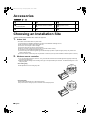
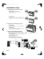
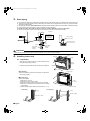
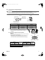
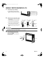
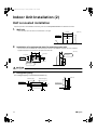
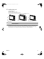
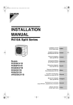
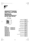
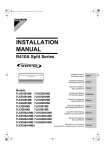
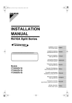
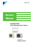
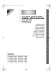
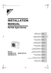
00_CV_3P191292-1F.fm Page 1 Tuesday, September 7, 2010 3:38 PM
INSTALLATION
MANUAL
R410A Split Series
Installation manual
R410A Split series
Installationsanleitung
Split-Baureihe R410A
Deutsch
Manuel d’installation
Série split R410A
Français
Montagehandleiding
R410A Split-systeem
Manual de instalación
Serie Split R410A
Models
FVXS25FV1B
FVXS35FV1B
FVXS50FV1B
English
Manuale d’installazione
Serie Multiambienti R410A
Εγχειρßδιο εγκατÜστασηò
διαιροýìενηò σειρÜò R410A
Manual de Instalação
Série split R410A
Рóêоводство по монтажó
Серия R410A с раздельной óстановêой
Montaj kýlavuzlarý
R410A Split serisi
Nederlands
Español
Italiano
ΕλληνικÜ
Portugues
Рóссêий
Türkçe
01_EN_3P191292-1F.fm Page 1 Tuesday, September 7, 2010 3:44 PM
Safety Precautions
• Read these Safety Precautions carefully to ensure correct installation.
• This manual classifies the precautions into WARNING and CAUTION.
Be sure to follow all the precautions below: they are all important for ensuring safety.
WARNING...............Failure to follow any of WARNING is likely to result in such grave consequences as death or serious injury.
CAUTION...............Failure to follow any of CAUTION may result in grave consequences in some cases.
• The following safety symbols are used throughout this manual:
Be sure to observe this instruction.
Be sure to establish an earth connection.
Never attempt.
• After completing installation, test the unit to check for installation errors. Give the user adequate instructions concerning the use
and cleaning of the unit according to the Operation Manual.
WARNING
• Installation should be left to the dealer or another professional.
Improper installation may cause water leakage, electrical shock, or fire.
• Install the air conditioner according to the instructions given in this manual.
Incomplete installation may cause water leakage, electrical shock, or fire.
• Be sure to use the supplied or specified installation parts.
Use of other parts may cause the unit to come to lose, water leakage, electrical shock, or fire.
• Install the air conditioner on a solid base that can support the weight of the unit.
An inadequate base or incomplete installation may cause injury in the event the unit falls off the base.
• Electrical work should be carried out in accordance with the installation manual and the national electrical wiring
rules or code of practice. Insufficient capacity or incomplete electrical work may cause electrical shock or fire.
• Be sure to use a dedicated power circuit. Never use a power supply shared by another appliance.
• For wiring, use a cable length enough to cover the entire distance with no connection.
Do not use an extension cord. Do not put other loads on the power supply, use a dedicated power circuit.
(Failure to do so may cause abnormal heat, electric shock or fire.)
• Use the specified types of wires for electrical connections between the indoor and outdoor units.
Firmly clamp the interconnecting wires so their terminals receive no external stresses. Incomplete connections or clamping may cause terminal overheating or fire.
• After connecting interconnecting and supply wiring be sure to shape the cables so that they do not put undue force
on the electrical covers or panels.
Install covers over the wires. Incomplete cover installation may cause terminal overheating, electrical shock, or fire.
• If any refrigerant has leaked out during the installation work, ventilate the room.
(The refrigerant produces a toxic gas if exposed to flames.)
• After all installation is complete, check to make sure that no refrigerant is leaking out.
(The refrigerant produces a toxic gas if exposed to flames.)
• When installing or relocating the system, be sure to keep the refrigerant circuit free from substances other than the
specified refrigerant (R410A), such as air.
(Any presence of air or other foreign substance in the refrigerant circuit causes an abnormal pressure rise or rupture, resulting in injury.)
• During pump-down, stop the compressor before removing the refrigerant piping.
If the compressor is still running and the stop valve is open during pump-down, air will be sucked in when the refrigerant piping is removed,
causing abnormal pressure in the freezer cycle which will lead to breakage and even injury.
• During installation, attach the refrigerant piping securely before running the compressor.
If the compressor is not attached and the stop valve is open during pump-down, air will be sucked in when the compressor is run, causing
abnormal pressure in the freezer cycle which will lead to breakage and even injury.
• Be sure to establish an earth. Do not earth the unit to a utility pipe, arrester, or telephone earth.
Incomplete earth may cause electrical shock, or fire. A high surge current from lightning or other sources may cause damage to the air conditioner.
• Be sure to install an earth leakage breaker.
Failure to install an earth leakage breaker may result in electric shocks, or fire.
CAUTION
• Do not install the air conditioner in a place where there is danger of exposure to inflammable gas leakage.
If the gas leaks and builds up around the unit, it may catch fire.
• Establish drain piping according to the instructions of this manual.
Inadequate piping may cause flooding.
• Tighten the flare nut according to the specified method such as with a torque wrench.
If the flare nut is tightened too hard, the flare nut may crack after a long time and cause refrigerant leakage.
1
■English
01_EN_3P191292-1F.fm Page 2 Tuesday, September 7, 2010 3:44 PM
Accessories
Indoor unit
A –
I
A Mounting plate
1
D Insulation sheet
2
G AAA dry-cell batteries
2
B Titanium Apatite Photocatalytic
Air-Purifying Filter
2
E Wireless remote controller
1
H Operation manual
1
C Drain hose
1
F Remote controller holder
1
I Installation manual
1
Choosing an Installation Site
• Before choosing the installation site, obtain user approval.
1.
Indoor unit
• The indoor unit should be sited in a place where:
1) the restrictions on installation specified in the indoor unit installation drawings are met,
2) both air intake and exhaust have clear paths met,
3) the unit is not in the path of direct sunlight,
4) the unit is away from the source of heat or steam,
5) there is no source of machine oil vapour (this may shorten indoor unit life),
6) cool (warm) air is circulated throughout the room,
7) the unit is away from electronic ignition type fluorescent lamps (inverter or rapid start type) as they may shorten the
remote controller range,
8) the unit is at least 1 metre away from any television or radio set (unit may cause interference with the picture or sound).
2.
Wireless remote controller
1) Turn on all fluorescent lamps in the room, if any, and find site where remote controller signals are properly received by
the indoor unit (within 7m).
2) Make the dipswitch settings. Set according to the type of unit purchased by the customer. The default settings are on the
heat pump side.
• For cooling only
Set the dipswitches on the cooling only side.
Dipswitches
H/P
C/O
• For heat pump
Check that the dipswitches are on the heat pump side.
If they are set on the cooling only side, move them to the heat pump side.
Dipswitches
H/P
■English
C/O
2
01_EN_3P191292-1F.fm Page 3 Tuesday, September 7, 2010 3:44 PM
Indoor Unit Installation Drawings
The indoor unit may be mounted in any of the three styles shown here.
Exposed
Half concealed
Concealed
A Mounting
plate
Molding
Floor Installation
Grid (Field supply)
Wall Installation
Location for securing the installation panel.
64
(700)
(Unit: mm)
150
26
134
230
(600)
140
250
0
21
574
644
35
0
16
35
Front grille
70mm or more
Air filter
50mm or more
from walls
B Titanium Apatite Photocatalytic
Air-Purifying Filter (2)
Front panel
E Wireless remote
controller
Screws
(Field supply: M3 × 20L)
3
50mm or more
from walls
Caulk pipe
hole gap
with putty.
F Remote controller
holder
■English
01_EN_3P191292-1F.fm Page 4 Tuesday, September 7, 2010 3:44 PM
Installation Tips
1.
Removing and installing front panel
• Removal method
1) Slide until the 2 stoppers click into place.
2) Open the front panel forward and undo the string.
3) Remove the front panel.
• Installation method
1) Attach the front grille and front panel after pulling the string
around them.
2) Close the front panel and slide until the stoppers click outside.
2.
Removing and installing front grille
3 tabs
Front grille
• Removal method
Casing
1) Open the front panel.
2) Remove the 4 screws and remove the front grille while pulling
it forward (3 tabs).
• Installation method
Remove
front grille
1) Secure the front grille with the 4 installation screws (3 tabs).
2) Return the front panel to the original position.
3.
Front panel
How to set the different addresses
When two indoor units are installed in one room, the two
wireless remote controllers can be set for different addresses.
Remove 4 screws.
1) Remove the front grille.
2) Live the sensor securing plate and remove the front metal plate cover.
3) Remove connectors 5P, 6P, and 7P.
4) Remove the electric box (1 screw).
5) Remove the thermistor.
6) Remove the side metal plate cover (7 tabs).
7) Cut the address jumper (JA) on the printed circuit board.
8) Cut the address jumper (J4) in the remote controller.
5) Thermistor
3) Connector 6P
JA
JA ADRESS
1
EXIST
CUT
2
3) Connector 5P
Open the front panel
J4
2) Sensor
securing
plate
3) Connector 7P
4) Remove 1 screw.
6) Side metal plate cover
2) Front metal plate cover
■English
J4 ADRESS
1
EXIST
CUT
2
4
01_EN_3P191292-1F.fm Page 5 Tuesday, September 7, 2010 3:44 PM
Indoor Unit Installation (1)
Exposed installation
1.
Refrigerant piping
1)
2)
3)
4)
Drill a hole (65mm in diameter) in the spot indicated by the
symbol in the illustration as below.
The location of the hole is different depending on which side of the pipe is taken out.
For piping, see 6. Connecting the refrigerant pipe, under Indoor Unit Installation (1).
Allow space around the pipe for a easier indoor unit pipe connection.
(Unit : mm)
60
45
Wall
Left bottom piping
75
75
Right bottom piping
45
75
Right back piping
Left/right piping
45
45
75
45
Left back piping
CAUTION
Min. allowable length
• The suggested shortest pipe length is 2.5m, in order to avoid noise from the outdoor unit and vibration.
(Mechanical noise and vibration may occur depending on how the unit is installed and the environment in which it is used.)
• See the installation manual for the outdoor unit for the maximum pipe length.
• For multi-connections, see the installation manual for the multi-outdoor unit.
Wall
45
350
75
Refrigerant pipe
Floor
2.
Boring a wall hole and installing wall embedded pipe
• For walls containing metal frame or metal board, be sure to use a
wall embedded pipe and wall cover in the feed-through hole to
prevent possible heat, electrical shock, or fire.
• Be sure to caulk the gaps around the pipes with caulking material
to prevent water leakage.
1) Bore a feed-through hole of 65mm in the wall so it has a down
slope toward the outside.
2) Insert a wall pipe into the hole.
3) Insert a wall cover into wall pipe.
4) After completing refrigerant piping, wiring, and drain piping,
caulk pipe hole gap with putty.
5
Inside
Wall embedded pipe
(Field supply)
Outside
Caulking
φ65
Wall hole cover
(Field supply)
Wall embedded pipe
(Field supply)
■English
01_EN_3P191292-1F.fm Page 6 Tuesday, September 7, 2010 3:44 PM
3.
Drain piping
1) Use commercial rigid polyvinyl chloride pipe (general VP 20 pipe, outer diameter 26mm, inner diameter 20mm) for the drain pipe.
2) The drain hose (outer diameter 18mm at connecting end, 220mm long) is supplied with the indoor unit. Prepare the drain
pipe picture below position.
3) The drain pipe should be inclined downward so that water will flow smoothly without any accumulation. (Should not be trap.)
4) Insert the drain hose to this depth so it won’t be pulled out of the drain pipe.
5) Insulate the indoor drain pipe with 10mm or more of insulation material to prevent condensation.
6) Remove the air filters and pour some water into the drain pan to check the water flows smoothly.
(Unit: mm)
150
100
Insert drain hose
to this depth so
it won’t be pulled
out of drain pipe.
100
Must be no trap.
Do not touch water.
220
C Drain hose
50mm
or more
Reducer
Vinyl chloride
drain pipe
(VP-20)
Vinyl chloride
drain pipe
(VP-30)
CAUTION
Use polyvinyl chloride adhesive agent for gluing. Failure to do so may cause water leakage.
4.
Installing indoor unit
3 tabs
Front grille
Casing
4-1. Preparation
• Open the front panel, remove the 4 screws and dismount the
front grille while pulling it forward.
• Follow the procedure below when removing the slit portions.
Remove
front grille
Front panel
Remove 4 screws.
Open the front panel.
■ For Moldings
• Remove the pillars. (Remove the slit portions on the bottom
frame using nippers.)
■ For Side Piping
• Remove the pillars.
1) Remove the 7 screws.
2) Remove the upper casing (2 tabs).
3) Remove the left and right casings (2 tabs on each side).
4) Remove the slit portions on the bottom frame and casings
using nippers.
5) Return by following the steps in reverse order (3 > 2 > 1).
For Moldings
2) Upper casing
3) Side
casings
3) Side casings
Remove 7 screws.
Remove the pillar.
For Side Piping
Casing
Bottom frame
Casing
Remove the pillar.
Remove the pillar.
■English
6
01_EN_3P191292-1F.fm Page 7 Tuesday, September 7, 2010 3:44 PM
Indoor Unit Installation (1)
4-2. Installation
• Secure using 6 screws for floor installations. (Do not forget to secure to the rear wall.)
• For wall installations, secure the A mounting plate using 5 screws and the indoor unit using 4 screws.
• The mounting plate should be installed on a wall which can support the weight of the indoor unit.
1) Temporarily secure the mounting plate to the wall, make sure that the panel is completely level, and mark the boring
points on the wall.
2) Secure the mounting plate to the wall with screws.
The mounting plate
should be installed on a
wall which can support the
weight of the indoor unit.
Floor Installation
Wall Installation
A Mounting plate
Casing
5 screws
(M4 × 25L)
(Field supply)
4 screws (M4 × 25L)(Field supply)
6 screws (M4 × 25L)(Field supply)
Molding
3) Once refrigerant piping and drain piping connections are complete, fill in the gap of the through hole with putty.
A gap can lead to condensation on the refrigerant pipe, and drain pipe, and the entry of insects into the pipes.
4) Attach the front panel and front grille in their original positions once all connections are complete.
5.
Flaring the pipe end
1)
2)
3)
4)
5)
Cut the pipe end with a pipe cutter.
Remove burrs with the cut surface facing downward so that the chips do not enter the pipe.
Fit the flare nut on the pipe.
Flare the pipe.
Check that the flaring is properly made.
WARNING
1)
2)
3)
4)
5)
6)
Do not use mineral oil on flared part.
Prevent mineral oil from getting into the system as this would reduce the lifetime of the units.
Never use piping which has been used for previous installations. Only use parts which are delivered with the unit.
Do never install a drier to this R410A unit in order to guarantee its lifetime.
The drying material may dissolve and damage the system.
Incomplete flaring may cause refrigerant gas leakage.
Flare’s inner
surface must
be scratch-free.
Flaring
Set exactly at the position shown below.
A
(Cut exactly
at right
angles.)
7
Remove
burrs
Die
A
Flare tool for R410A
Conventional flare tool
Clutch-type
Clutch-type (Rigid-type) Wing-nut type (Imperial-type)
0-0.5mm
1.0-1.5mm
1.5-2.0mm
The pipe end must
be evenly flared in
a perfect circle.
Make sure that the
flare nut is fitted.
■English
01_EN_3P191292-1F.fm Page 8 Tuesday, September 7, 2010 3:44 PM
6.
Connecting the refrigerant pipe
CAUTION
1) Use the flare nut fixed to the main unit. (To prevent cracking of the flare nut by aged deterioration.)
2) To prevent gas leakage, apply refrigeration oil only to the inner surface of the flare. (Use refrigeration oil for R410A.)
3) Use torque wrenches when tightening the flare nuts to prevent damage to the flare nuts and gas leakage.
Align the centres of both flares and tighten the flare nuts 3 or 4 turns by hand. Then tighten them fully with the torque wrenches.
[Apply oil]
[Tighten]
Apply refrigeration oil to
the inner surface of the
flare.
Do not apply refrigeration
oil to the outer surface.
Torque wrench
Flare nut
Spanner
Piping union
Flare nut
Do not apply refrigeration
oil to the flare nut avoid
tightening with over torque.
Flare nut tightening torque
Gas side
Liquid side
25/35 class
50 class
3/8 inch
1/2 inch
25/35/50 class
1/4 inch
32.7-39.9N·m
(333-407kgf·cm)
49.5-60.3N·m
(505-615kgf·cm)
14.2-17.2N·m
(144-175kgf·cm)
6-1. Caution on piping handling
1) Protect the open end of the pipe against dust and moisture.
2) All pipe bends should be as gentle as possible. Use a pipe bender
for bending.
Wall
Be sure to
place a cap.
Rain
6-2. Selection of copper and heat insulation
materials
• When using commercial copper pipes and fittings, observe the following:
1) Insulation material: Polyethylene foam
Heat transfer rate: 0.041 to 0.052W/mK (0.035 to 0.045kcal/(mh°C))
Refrigerant gas pipe’s surface temperature reaches 110°C max.
Choose heat insulation materials that will withstand this temperature.
If no flare cap is
available, cover
the flare mouth
with tape to keep
dirt or water out.
Inter-unit
wiring
Gas pipe
Gas pipe
insulation
Liquid pipe
Liquid pipe
Finising tape insulation
2) Be sure to insulate both the gas and liquid piping and to provide insulation dimensions as below.
Gas side
25/35 class
50 class
Gas pipe thermal insulation
Liquid side
O.D. 9.5mm
O.D. 12.7mm
O.D. 6.4mm
Minimum bend radius
30mm or more 40mm or more 30mm or more
Thickness 0.8mm (C1220T-O)
Liquid pipe
thermal
25/35 class
50 class
insulation
I.D. 12-15mm I.D. 14-16mm I.D. 8-10mm
Thickness 10mm Min.
3) Use separate thermal insulation pipes for gas and liquid refrigerant pipes.
■English
8
01_EN_3P191292-1F.fm Page 9 Tuesday, September 7, 2010 3:44 PM
Indoor Unit Installation (1)
7.
Checking for gas leakage
1) Check for leakage of gas after air purging.
2) See the sections on air purges and gas leak
checks in the installation manual for the outdoor
unit.
Check for leakage here.
• Apply soapy water and
check carefully for leaking
gas.
• Wipe soapy water off after
the check is complete.
8.
Attaching the connection pipe
• Attach the pipe after checking for gas leakage,
described above.
1) Cut the insulated portion of the on-site piping,
matching it up with the connecting portion.
2) Secure the slit on the refrigerant piping side
with the butt joint on the auxiliary piping using
the tape, making sure there are no gaps.
1)
2)
Refrigerant
pipe
Slit
3)
Refrigerant
pipe
Refrigerant
pipe
Slit
D Insulation
sheet
3) Wrap the slit and the butt joint with the included
D insulation sheet, making sure there are no
gaps.
Tape
Auxiliary pipe
CAUTION
1) Insulate the joint of the pipes securely.
Incomplete insulation may lead to water leakage.
2) Push the pipe inside so it does not place undue force on the front grille.
9.
Connecting the drain hose
Insert the supplied C drain hose into the
socket of the drain pan.
Fully insert the drain hose until it adheres to
a seal of the socket.
Drain pan
Seal
Drain pan
C Drain hose
Seal
C Drain hose
9
■English
01_EN_3P191292-1F.fm Page 10 Tuesday, September 7, 2010 3:44 PM
10.Wiring
With a Multi indoor unit , install as described in the installation manual supplied with the Multi outdoor unit.
• Live the sensor securing plate, remove the front metal plate cover, and connect the branch wiring to the terminal block.
1) Strip wire ends (15mm).
2) Match wire colours with terminal numbers on indoor and outdoor unit’s terminal blocks and firmly screw wires to the
corresponding terminals.
3) Connect the earth wires to the corresponding terminals.
4) Pull wires to make sure that they are securely latched up, then retain wires with wire retainer.
5) Make sure that the wires do not come in contact with the metal conduit for the heat exchanger.
6) In case of connecting to an adapter system. Run the remote controller cable and attach the S21. (Refer to 11. When
connecting to an HA system.)
Sensor securing plate
Firmly fix the wires with
the terminal screws.
Shape wires so
that the front metal
plate cover will fit
securely.
Outdoor unit
1
2
3
Terminal block
Electrical
component
box
Firmly secure wire
retainer so that
wires sustain no
external stress.
Wire retainer
When wire length exceeds 10m,
use 2.0mm diameter wires.
LN
1
Indoor 2
3
unit
Firmly fix the wires with
the terminal screws.
Use the specified
wire type.
Front metal
plate cover
1 23
H05VV
Make sure that the wires
do not come in contact
with the metal conduit
for the heat exchanger.
WARNING
1) Do not use tapped wires, stranded wires, extension cords, or starburst connections, as they may cause overheating, electrical
shock, or fire.
2) Do not use locally purchased electrical parts inside the product. (Do not branch the power for the drain pump, etc.,
from the terminal block.) Doing so may cause electric shock or fire.
3) Do not connect the power wire to the indoor unit. Doing so may cause electric shock or fire.
11. When connecting to an HA system
1) Remove the electric box. (See 3. How to set
the different addresses on page 4.)
2) Cut off the pins using a nipper.
3) Wire as shown in the diagram and connect
the connection cord to the S21 connector.
4) Attach the side metal plate cover and
thermistor sensor and return the electric box
to its previous state.
5) Attach connectors 5P, 6P, and 7P.
6) Replace the front metal plate cover and the
sensor securing plate.
HA connector
(S21)
Sensor
securing
plate
S2
1
Side metal plate cover
HA cord
2) Pin
Front metal plate cover
■English
10
01_EN_3P191292-1F.fm Page 11 Tuesday, September 7, 2010 3:44 PM
Indoor Unit Installation (2)
Half concealed installation
Only items peculiar to this installation method are given here. See Exposed Installation for additional instructions.
1.
Wall hole
• Drill a wall hole of the size shown in the illustration on the right.
670-690
(Unit: mm)
585-595
Open size
Opening hole
Floor
2.
Installation of supplemental plate for attaching main unit
• The rear of the unit can be fixed with screws at the points shown in the illustration as below. Be sure to install the
supplemental plate in accordance with the depth of the inner wall.
Fixing point
on the back
Supplemental plate
(Field supply)
Screw hole
Screw hole
150
(Unit: mm)
95
644
140
250
Opening hole
230
250
Supplemental plate
(Field supply)
200
CAUTION
1) The supplemental plate for installing the main unit must be used, or there will be a gap between the unit and the wall.
3.
Refrigerant piping
See 1. Refrigerant piping under Indoor Unit Installation (1)
Wall
Left bottom piping
(Unit: mm)
Right bottom piping
50
35
Hole location
Right/left piping
45
Wall
75
11
75
50
■English
01_EN_3P191292-1F.fm Page 12 Tuesday, September 7, 2010 3:44 PM
4.
Installing indoor unit
1)
2)
3)
4)
5)
Remove the front grille.
Remove 7 screws.
Remove the upper casing (2 tabs).
Remove the side casings (2 tabs on each side).
Attach the indoor unit to the wall and secure using screws in 6 locations (M4 × 25L).
Upper casing
Side casing
Remove 7 screws.
6 screws
(M4 × 25L)(Field supply)
CAUTION
1) Use drain pan edge for horizontal projection of the indoor unit.
2) Install the indoor unit flush against wall.
NOTE:
For refrigerant piping, Boring a wall hole and installing wall embedded pipe, drain piping, installing indoor unit,
flaring the pipe end, connecting the refrigerant pipe, checking for gas leakage, attaching the connection pipe,
connecting the drain hose, wiring, when connecting to an HA system, see Exposed Installation.
■English
12
01_EN_3P191292-1F.fm Page 13 Tuesday, September 7, 2010 3:44 PM
Indoor Unit Installation (3)
Concealed installation
Only items peculiar to this installation method are given here. See Exposed Installation for additional instructions.
Install the unit according to the instructions below. Failure to do so may cause lead to both cooling and heating failure
and the condensation inside the house.
1) Allow enough space between the main unit and ceiling not to obstruct the flow of cool/warm air.
2) Place a partition plate between outlet and inlet sections.
3) Place a partition plate on the right side.
4) Change the upward-blow limit switch.
5) Use a movable lattice at the air outlet to allow the adjustment of cool/warm air flow direction.
6) Lattice size should be 70% or more of open rate.
(Unit: mm)
Right side partition plate
Partition plate
50 or more
50 or more
Right side partition plate
partition plate
Movable lattice
15-20
70 or more
Upper lattice
must not
project
410
70% or more
of open rate
partition plate
120
Movable lattice
40 or less
20-30
13
■English
01_EN_3P191292-1F.fm Page 14 Tuesday, September 7, 2010 3:44 PM
1.
Refrigerant piping
Left bottom piping
(Unit: mm)
Right bottom piping
Right/left piping
45
60
45
Hole location
75
75
45
2.
Changing upward air flow dipswitch
Change the upward air flow dipswitch (SW2-4) to ON to limit the upward air flow.
1) Remove the front grille.
2) Switch the dipswitch (SW2-4) on the PCB in the electrical equipment box to ON.
• How to set and use the switch
Upward air flow dipswitch
Switch number
SW2-4
Set function
Upward air flow limit
ON
ON
OFF
OFF
Use
Switch to on for
embedded units
Factory setting
OFF
CAUTION
Be sure to turn on the upward air flow switch. Failure to do so may cause incomplete cooling/heating and formation of
condensation inside the house.
NOTE:
For refrigerant piping, Boring a wall hole and installing wall embedded pipe, drain piping, installing indoor unit,
flaring the pipe end, connecting the refrigerant pipe, checking for gas leakage, attaching the connection pipe,
connecting the drain hose, wiring, when connecting to an HA system, see Exposed Installation.
■English
14
01_EN_3P191292-1F.fm Page 15 Tuesday, September 7, 2010 3:44 PM
Trial Operation and Testing
1.
Trial operation and testing
1-1 Measure the supply voltage and make sure that it falls in the specified range.
1-2 Trial operation should be carried out in either cooling or heating mode.
■ For Heat pump
• In cooling mode, select the lowest programmable temperature; in heating mode, select the highest programmable
temperature.
1) Trial operation may be disabled in either mode depending on the room temperature.
Use the remote controller for trial operation as described below.
2) After trial operation is complete, set the temperature to a normal level (26°C to 28°C in cooling mode, 20°C to 24°C in
heating mode).
3) For protection, the system disables restart operation for 3 minutes after it is turned off.
■ For Cooling only
• Select the lowest programmable temperature.
1) Trial operation in cooling mode may be disabled depending on the room temperature.
Use the remote controller for trial operation as described below.
2) After trial operation is complete, set the temperature to a normal level (26°C to 28°C).
3) For protection, the unit disables restart operation for 3 minutes after it is turned off.
1-3 Carry out the test operation in accordance with the Operation Manual to ensure that all functions and parts,
such as louver movement, are working properly.
• The air conditioner requires a small amount of power in its standby mode. If the system is not to be used for some
time after installation, shut off the circuit breaker to eliminate unnecessary power consumption.
• If the circuit breaker trips to shut off the power to the air conditioner, the system will restore the original operation
mode when the circuit breaker is opened again.
Trial Operation from Remote Controller
1) Press ON/OFF button to turn on the system.
2) Press TEMP (2 locations) and MODE at the same time.
3) Press MODE button twice.
(“ ” will appear on the display to indicate that Trial Operation mode is selected.)
4) Trial run mode terminates in approx. 30 minutes and switches into normal mode. To quit a trial operation, press ON/OFF
button.
2.
Test items
Test Items
Symptom
Indoor and outdoor units are installed properly on solid bases.
Fall, vibration, noise
No refrigerant gas leaks.
Incomplete cooling/heating
function
Refrigerant gas and liquid pipes and indoor drain hose extension are
thermally insulated.
Water leakage
Draining line is properly installed.
Water leakage
System is properly earthed.
Electrical leakage
The specified wires are used for inter-unit wiring connections.
Inoperative or burn damage
Indoor or outdoor unit’s air intake or exhaust has clear path of air.
Stop valves are opened.
Incomplete cooling/heating
function
Indoor unit properly receives remote controller commands.
Inoperative
15
Check
■English
00_CV_3P191292-1F.fm Page 2 Tuesday, September 7, 2010 3:38 PM
Two-dimensional bar code is a code
for manufacturing.
3P191292-1F M06B131E
(1010) HT