1
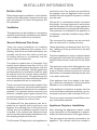
User- and installation manual
Vesuvius 100, Vesuvius 140
WARNING - THE COMBUSTION CHAMBER OF THIS STOVE SHOULD
ONLY BE OPENED AND SERVICED BY A REGISTERED GAS INSTALLER
(i.e. GAS SAFE REGISTERED ENGINEER[GB])
These instructions should be left with the customer for future reference
This Manual Covers the following appliances:
Vesuvius 100, Vesuvius 140
Contents
GENERAL INFORMATION............................................................................................................3
Important Safety Notice..................................................................................................................3
General Fitting Information....................................................................................................4
USER INFORMATION...................................................................................................................5
Remote Control Electronic Ignition System RCE GV60................................................................5
INSTALLER INFORMATION.......................................................................................................10
Ventilation............................................................................................................................10
General Balanced Flue Notes / Appliance Fireplace installation.........................................10
Terminal Locations Wall Mounting.......................................................................................12
Terminal Locations Roof Termination...................................................................................13
Concentric Flue Parts Identification.....................................................................................14
Rigid Balanced Flue Connection Possibilities......................................................................21
Vertical Roof Terminations...................................................................................................22
Installing Remote Control Electronic Ignition System GV60........................................................25
Arranging The Ceramic Fire-bed..................................................................................................26
Log Arrangements...............................................................................................................24
Gravel Arrangements...................................................................................................................30
COMMISSIONING THE APPLIANCE..........................................................................................30
Installation tips.............................................................................................................................31
Installing the fire .........................................................................................................31
Servicing Instructions...................................................................................................................34
Troubleshooting............................................................................................................................34
TECHNICAL INFORMATION.......................................................................................................37
Dimensions..................................................................................................................................37
Technical Details..........................................................................................................................39
Warranty.......................................................................................................................................42
GENERAL INFORMATION
Important Safety Notice
ing regulations. It is therefore recommend that
a registered gas installer be employed for this
This appliance has a ceramic Fire-bed arrangement; this contains Refractory Ceramic Fibres,
which are man-made vitreous silicate fibres.
Excessive exposure to these materials can
task. The engineer will provide you with information about the safety limits of the installation and
should fix a notice plate in a place where it can
be readily seen.
cause irritation to eyes, skin and respiratory
organs. Hence we recommend that when handling these materials the release of dust should
be kept to a minimum. During installation and
servicing we recommend that a HEPA filtered
This appliance is designed as an efficient heating
device and consequently all body parts become
very hot in use. Except for the control knob and
control access door, which are designed to stay
cool, all other parts are working surfaces and
should not be touched.
vacuum be used to remove any dust and soot
in and around the fire. If any of the ceramic
fire-bed components need to be replaced we
recommend that the removed parts be sealed in
a heavy-duty polythene bag, and be labelled as
RCF waste. RCF is not “Hazardous waste” and
The glass and frame on this appliance acts as
a fireguard conforming to BS: 1945 – 1971 and
satisfies the Heating Appliance (Fireguards)
regulations 1991. No part of the window or frame
should be permanently removed. It does not
give protection for young children aged or
infirm, extra guarding(conforming to BS8423:
can be disposed of at a licensed tipping site for
the disposal of industrial waste.
The appliance incorporates a permanent pilot.
This is located on the front of the burner, and
2002) should be considered so the special
hazards that exist in nurseries and other places
where there are young children, aged or infirm
persons are minimized.
must not be adjusted by the installer. This system
must not be put out of operation, and if any parts
require changing, only original manufacturer
parts shall be used.
Bearing in mind that the heat given off by this
This appliance is designed to be used either
Natural or LPG gas however, each individual
appliance may affect articles placed close to it,
curtains should not be placed within 30cm.
appliance is only capable of running off the type
of gas specified at the time of purchase. It is important to note that once a type of gas has been
The appliance is not designed as a dryer. It is not
therefore recommended that the appliance be
specified the stove cannot run off any other type.
The type of gas that your stove is capable of
used in such a manner. Do not place any articles
within 30cm of this appliance as this may result
in damage to the articles.
burning is stated on the data information panel.
The installation must be carried out in accordance with the following regulations:
This appliance has been designed, tested and
approved to meet standards in place for product use, performance and safety. Installation of
your appliance must comply with current build-
The Building Regulations issued by the Depart3
GENERAL INFORMATION
General Fitting Information
ment of the Environment, the Building Standards
(Scotland) (Consolidation) Regulations issued
Inlet pipe connection
8mm compression
Chimney requirements Balanced Flue
by the Scottish Development Department.
Flue monitor
BS 5440 part 1, BS 5871 part 2 and BS 6891.
Permanent Pilot
User control: Variable rotary control inc. integrated Piezo ignition, Permanent pilot facility, Flame
failure device and Oxygen Depletion Cut-out.
In the Republic of Ireland the installation must
also conform to the relevant standards, particularly in regard to flue sizing and ventilation. Refer
to documents IS813, ICP3, IS327 and any other
Before installation of these appliances, the area
into which the fire is to be fitted must be cleared
of all debris (including dust), in particular combustible material.
rules in force.
This appliance must be installed in accordance
with the rules in force and used only in a sufficiently ventilated space, and is intended for
use on a gas installation with a governed meter.
The appliance must sit on a hearth (or base
surface) sufficient to support the weight of the
fire. The firebox must then also be secured.
Adjustable brackets are supplied on the firebox
for this purpose.
Before installation, ensure that the local distribution conditions (identification of the type of gas
and pressure) and the adjustment of the appliance are compatible. The technical specification
of this appliance is given on the rear page of
this manual.
Do not use the appliance if the glass front
door or panel has been broken, removed or
is open.
Note:
Since the appliance is a source of heat, circulation of air occurs. Therefore it is of importance
that you do not use the appliance shortly after a
renovation of the home. Because of the natural
circulation of air, moist and volatile components
from paint, building materials, carpet etc. will
be attracted. These components can settle
themselves down onto cold surfaces in the form
of soot.
4
user information
Remote control electronic ignition
system RCE GV60
- temperature display in degrees Celsius or
Fahrenheit;
- time;
- thermostat function;
The appliance is supplied with a remote control.
Ignition, controlling the flame height and switching off are performed by the remote control that
operates a receiver in the control hatch. For
some appliances, no control hatch is supplied.
In that case, the receiver is placed under the
- timer for thermostat function.
Setting the communication code
Prior to putting the application into operation, a
communication code must be set between the
remote control and the receiver. The code is chosen randomly from the 65000 available codes.
As a result, the chance that other remote controls
near you are using the same code and affect the
operation of your appliance is very small.
appliance. The receiver and remote control are
battery powered. The receiver requires 4
penlite (AA type) batteries, the remote control
requires a 9V block battery. At normal use, the
batteries will have an average life of one year.
You can also use an optional adapter. Ask your
installer for information. In that case you will
need a 230 V connection near your appliance.
Follow the procedure described below:
Hold down the reset button on the receiver,
until you hear two consecutive sound signals
(see fig. 2). After the second, longer signal,
let go of the reset button.
(small flame) or button
Press button
( large flame) on the remote control within 20
1
seconds, until you hear an extra long sound
signal: this is the confirmation of a correct
communication.
!Caution When installing a new remote control or receiver, you must set a new communication code.
2
The appliance’s standard functions such as
ignition, controlling the flame
height, standby (pilot burner) position and
switching off are performed in the
MAN position, the manual control of the
remote control (see fig. 2).
In addition, the remote control can also be
used to set a number of additional
functions:
5
user information
MAN position
By briefly pressing the SET button, you will go
Ignite the appliance as follows:
Set button A on the gas control to
through the following functions:
MAN →
TEMP → TEMP → (P*)TIMER
ON (button B is controlled automatically).
→ MAN
where, depending on the timer setting:
(P*) is displayed as P1 , , P1
, P2
P2
.
The gas control is located in the control hatch
or is placed under the appliance.
,
Simultaneously press the buttons OFF and
(large flame) on the remote control.
Let go of the buttons when a short sound
You can also go back to the MAN position by
pressing the button
(small flame).
(large flame) or
signal indicates that the ignition process has
been started.
In succession:
- the continuous signals will indicate that the
ignition process is active;
- a short sound signal will indicate that the igni-
!Caution - When pressing the buttons
(with the exception of the SET button), the
transmission symbol (
) will appear to
indicate that transmission is taking place
between the remote control and the receiver;
- The receiver acknowledges the transmission
with a sound signal;
- The appliance will automatically enter the
tion process has finished;
- the appliance will automatically switch through
to the highest position of the main burner, which
will start to burn in a few seconds.
standby position, if there is no transmission
for 6 hours.
Set the remote control to the MAN position.
Caution - If the pilot burner is not burning
after 3 ignition attempts, you must close the
gas tap and call the installer;
- When igniting the pilot burner, you will hear
Ignition
sound signals. After the last short sound
signal, the main burner should be largely
Caution - During the ignition process, you
are not allowed to operate control button B
on the gas control manually
- Always wait 5 minutes after the pilot burner
has gone out, before you re-ignite
ignited within about 10 seconds. If this is
not the case, you must close the gas tap and
warn your installer;
- If the appliance ignites with a pop sound,
you must close the gas tap and
the appliance;
contact your installer.
3
!Tip A little motor will start to run when the
main burner operates, you will be able to
hear it.
A
B
6
user information
Flame height / standby
Time
The flame height can be adjusted continuously
by using the buttons (small flame) and (large
flame). By continuing to lower the flame height,
the appliance can be set to the standby position;
The display can indicate time.
After placing the battery or simultaneously press(large flame) and
(small flame), the
ing
time indication will flash on the display and you
this means that only the pilot burner will still be
burning.
Press button (small flame) to lower the flame
height and/or to set the appliance in the standby
position.
Press the button
(large flame) to raise the
will be able
to adjust the time.
Simultaneously press and until the time indication flashes on the display.
Press the button
(large flame) to set the
hours.
flame height and/or to switch on the main burner
from the standby (pilot burner) position.
Press the button (small flame) to set the
minutes.
Press OFF to return to the MAN position, or
wait for the system to automatically return
to the MAN position.
Caution - If you continue to press down
button
(large flame) on the remote control,
the main burner should be largely ignited
within about 10 seconds. If this is not the
case, you must close the gas tap and warn
your installer;
Thermostat function
Using the thermostat function you can set
two temperatures, which can be controlled
thermostatically. These temperatures are
referred to as day temperature and night
- If the appliance ignites with a pop sound,
you must close the gas tap and contact your
installer.
temperature.
The
TEMP and
TEMP symbols on the
display refer to day and night temperature
respectively.
Switching off
Switch the appliance off by pressing the OFF
button. The pilot burner will also go out.
The room temperature is compared to the set
day/night temperature and then the flame height
Temperature display
The room temperature can be indicated on the
display in degrees Celsius (°C) using a 24 hour
clock or degrees Fahrenheit (°F) using a 12
hour clock.
Simultaneously press OFF and
(small
flame), until the correct display appears.
is automatically controlled in order to reach the
set temperature.
To be able to use the day/night temperature
function, the appliance must be
in the standby position.
!Caution - Always leave the remote control
at the same place, so that the thermostat is
able to ‘feel’ the room temperature;
- Make sure this place is free from influences
such as draught, heat from radiators
and direct sunlight.
7
user information
Timer for thermostat function
Using the timer enables you to set two times per
24 hours for switching on the day temperature
and two times per 24 hours for switching on the
night temperature.
In order to control the night temperature, it
should be set to at least 5 °C / 40 °F.
If the night temperature is set to the “-- ” position,
the appliance will remain in the standby position.
The appliance will only switch on at the next
switch-on time of the day temperature.
The appliance must be in standby position in
order to be controlled by the timer.
Example
By using the Y TEMP function you can keep the
day temperature at 20 °C; while
you use the 4 TEMP function at night to maintain
a temperature of 15 °C.
Setting day/night temperature
By using the SET button, you will go through the
following functions:
MAN →
TEMP →
TEMP → (P*)TIMER
→ MAN
Briefly press the SET button to enter
the
TEMP or the
TEMP position.
Press the SET button until the temperature
on the display flashes.
Set the required temperature by using the
buttons
(large flame) and
(small flame).
!Caution - The minimum temperature you can
set is 5 °C / 40 °F;
- Control of the night temperature is switched
off by lowering the temperature
until two stripes (“--”) appear on the display.
Press the OFF button or wait until position
TEMP or
TEMP appears on the
display.
Example of switch times
You have set a day temperature and night
temperature of, for example, 20 °C and 15 °C.
P1
TIMER = 7 hours; the temperature will
go to 20 °C at 7 am.
TIMER = 9 hours; the temperature will
P1
go to 15 °C at 9 am.
P2
TIMER = 17 hours; the temperature will
go to 20 °C at 5 pm.
P2
TIMER = 22 hours; the temperature
returns to 15 °C at 10 pm.
Activating the thermostat function
For activating the thermostat function, you must
proceed with the following
steps:
Place the appliance in the standby (pilot
burner) position using button
(small flame).
Set the day/night temperature.
Choose the
TEMP or
TEMP function
using the SET button.
8
user information
Replacing the battery
If the battery is almost empty, the display will
show “BATT”.
Setting times for the timer
To set the timer, proceed as follows:
Set the day and night temperature as described
above
Briefly press the SET button to enter the (P*)
TIMER position.
Press the SET button until P1
TIMER is
displayed and the time flashes.
Set the first switch on time of the day temperature
(large flame) and (small
using the buttons
flame).
Briefly press the SET button to set the next time
of the cycle, P1
TIMER.
Successively set the times P2
TIMER and
P2
TIMER.
Press the OFF button or wait until position (P*)
TIMER appears on the display.
To replace the battery, proceed as follows:
Remove the cover at the back side of the
remote control.
Disconnect the 9V block battery from /
connect the 9V block battery to the connector.
!Caution - Observe the “+” and “-” poles of
the batteries and the connector;
- Use alkaline batteries;
- Batteries are regarded as “small chemical
waste” and may therefore not be disposed
with the household rubbish.
Place the battery in the holder.
Replace the cover.
Activating the timer function
Follow the steps below for activating the timer
control:
Place the appliance in the standby (pilot burner)
position using button
(small flame).
Set the day/night temperature if you have not
yet done so;
Set the timer times P1
TIMER, P1 TIMER,
P2
TIMER and P2
TIMER.
Choose the (P*) TIMER function using the SET
button.
9
installer information
Installation
restricted to the Flue systems as specified by
the supplier, thus the appliance must only be
installed with the original flue system, no others
may be used
The gas fire, in combination with the concentric
flue system , has been approved in accordance
with the European CE-norm for gas appliances
and may therefore be used only with this system.
The guarantee is invalidated if the appliance is
(completely or partially) installed using a different system.
Before beginning the installation, check that the
details on the rating plate correspond to the gas
type and pressure to which the appliance will
be connected.
Ventilation
This appliance can be installed in a completely
sealed or mechanically ventilated house without
extra ventilation and/or fume extraction.
The concentric flue systems can be used with
either a newly-built or existing chimney.
General Balanced Flue Notes
These appliances are designed with the “Firebox” raised up off the ground level by the built
in “Base unit”.
There are many possibilities for installing
this Concentric Balanced Flue system into a
building, both Roof and Wall terminations are
possible, and the flue can either be built into
an existing chimney or a completely new flue
system may be constructed.
Thus these appliances require no special Hearth
arrangements, as the floor will not get hot and is
protected by the steel construction of the “Base
unit”.
The system is based upon a Concentric Flue
system which utilises an inner flue of 100 or 130
mm diameter which passes through an outer flue
of 150 or 200 mm diameter. The flue gasses that
are the products of combustion of the fire, pass
through the inner flue and are safely vented to
the outside environment. The gap between the
inner and outer flues is the channel by which the
stove is supplied with air for combustion.
The appliance must not be fitted against a rear
wall constructed from a combustible material;
a gap of 300mm should be given all round the
stove before combustible materials may be used
in the wall construction.
If the appliance has to be located in an opening, a minimum clearance of 50mm should be
allowed to non-combustible materials.
These concentric flues terminate outside of the
property in a terminal, this terminal will keep the
expelled gasses and the fresh air for combustion
separate. It is important that the terminal is not
blocked, a suitable guard maybe required if the
terminal is located at a “Low” level (usually when
the terminal is within 2m of floor level).
If the appliance is located in a recess, then the
recess must have adequate ventilation, we recommend a minimum total vent area of 200 cm².
The stove must be located at least 280mm from
any combustible materials.
The Balanced Flue gas appliance can be installed as an insertion into an existing or new
fireplace. If an existing Flue or Chimney is to be
utilised, then the installation engineer must be
consulted. If the chimney has been previously
used it must be professionally cleaned and certified as being sound and fit for use.
Appliance Fireplace Installation
After selecting the appliance location, install
a gas connection for the appliance in approximately the desired location of the gas controls.
The gas controls are already connected to the
appliance. The controls need to be located in
The European CE approval on this appliance is
10
installer information
Carport or Building Extension
the control access box, so an appropriate position for the access box need to be determined.
This appliance has adjustable legs, these must
me set to stabalise the fire before flue position
is finalised.
Where a flue terminal is sited within a carport or
building extension, it should have at least two
completely open and unobstructed sides. The
distance between the lowest part of the roof
and the top of the terminal should be at least
600mm.
Do not make any adjustments to the appliance,
except the leg length.
The appliance and Flue system should be fitted
with a minimum clearance of 500mm from any
combustible objects or materials, this includes
any combustible materials used for the fireplace
construction.
Note: A covered passageway should not be
treated as a carport. Flues should not be sited
in a covered passageway between properties.
Basements,Lightwells and Retaining
walls
As this is a room sealed appliance and the appliance stands on appropriate legs, a hearth is
not required for this appliance.
Flue terminals should not be sited within the confines of a basement area, light well or external
space formed by a retaining wall, unless steps
are taken to ensure the products of combustion can disperse safely at all times. It may be
possible to install this Balanced Flue system in
such a location provided that it is not sited lower
than 1m from the top level of that area to allow
combustion products to disperse safely.
The Fireplace should be ventilated with openings
giving a total free vent area of 200 cm².
A gap of 50mm should be left all round the appliance.
If a shelf is to be fitted above the fireplace opening, a gap of 150mm minimum should be left
between the opening and the shelf.
The brackets supplied may be used fore securing the appliance to a rear wall.
Flue terminals should be sited to ensure total
clearance of the combustion products in accordance with the inclosed information.
Timber Frame Construction
When the products of combustion are discharged, they should not cause a nuisance to
adjoining or adjacent properties and they should
be positioned so that damage cannot occur to
other parts of the building. If the outer wall surface is constructed of combustible material, a
non-combustible plate should be fitted behind
the terminal projecting 25mm beyond the external edges of the terminal.
Whilst it is possible to install room-sealed appliances in timber frame properties, great care
needs to be taken to ensure that the flue assembly does not interfere with the weather proofing
qualities of any outer wall which it may penetrate.
Before attempting this work, further details need
to be referenced, (e.g. “Gas Installations in Timber Frame Buildings” from the CORGI installer
series in the UK).
11
installer information
Terminal Locations Wall Mounting
Dimension
Distance (mm)
Terminal Position
A*
Directly below an opening,air brick, opening window etc.
B
Above an opening,air brick, opening window etc.
300
C
Adjacent to an opening,air brick, opening window etc.
400
D
Below gutters, soil pipes or drain pipes
300
E
Below eaves
300
F
Below balconies of car port roof
600
G
From a vertical drain pipe or soil pipe
300
H
From an internal or external corner
600
I
Above ground roof or balcony level
300
J
From a surface facing the terminal
600
K
From a terminal facing the terminal
600
L
From an opening in the car port (e.g. door , window into the dwelling)
1200
M
Vertically from a terminal on the same wall
1500
N
Horizontally from a terminal on the same wall
300
P
From a vertical structure on the roof
600
Q
Above intersection with roof
150
600
* I addition, the terminal should not be nearer than 300mm to an opening in the building fabric
formed for the purpose of accomodating a built in element such as a window frame.
12
installer information
Terminal Locations Roof Termination
“Distance” = minimum distance required for positioning of the outlet to avoid adverse effects
with respect to:
A.
A ventilation opening serving an occupied room, a toilet or a bathroom
B.
A heating air supply, when the supply flows through an occupied room.
C.
A window that can be opened and that is near an occupied room, a toilet or a bathroom.
Distance: outlet To avoid adverse effects
A,B or C
At the same roof level
>6 m (*)
At a different roof level
>3 m (*) (**)
At a lower positioned wall
>2 m (**)
At a higher sloping surface
>6 m (***)
(*)
If the required distance cannot be achieved, the outlet position rules take precedence.
(**)
If the outlet is positioned at least 1 m higher than the intake supply opening, or a window
that can be opened.
(***) If the required distance cannot be achieved, the position of the outlet must be at least 1 m
above the highest facade/roof.
Important note for Roof Terminations (C31).
When installing the appliance with a roof termination (classification C31), it is important to fit a
flue restriction strip across the flue outlet inside the stove, see following notes.
Minimum Vertical Length notes.
Roof terminations may be installed from a minimum height 1.0 m this is shown on the pages that
follow.
13
installer information
Concentric Flue Parts Identification
The following pages identify the parts that may be used in the Balanced Flue installation of this
appliance.
The Item number in the table refers to the item number of the part in the Identification pages, this
Item number is also the number that will be used to identify parts in the Installation suggestion
diagrams.
Item
A
B
C
D
E
F
G
1
2
3
4
5
6
7
8
9
10
11
12
13
14
15
16
18
19
20
21
22
23
24
25
Description
Appliance
Appliance Connector
Flue Adaptor
Chimney or Flue, Fully Gas Tight Ø150 minimum
Chimney or Flue, Fully Gas Tight Ø160 minimum
Stainless Steel Flexible Chimney Liner Ø100, AISI 316Ti
Stainless Steel Flexible Chimney Liner Ø150, AISI 316Ti
Concentric Flue Pipe 250mm Length
Concentric Flue Pipe 500mm Length
Concentric Flue Pipe 1m Length
Locking Band
Protection Band
Concentric Flue Pipe Adjustable Length 50 - 300mm
Vertical Terminal
Horizontal Terminal (Excentric Exit) Ø100
Mounting Band
Wall Band Adjustable
Concentric Flue 90°
Concentric Flue 45°
Concentric Flue 15°
Storm Collar
Flat Roof Flashing (Aluminium)
Flat Roof Flashing
Slope Roof Flashing 5° - 30°
Slope Roof Flashing 20° - 45°
Adjustable Roof Plate (Supplied as pair)
Wall Cover
Flue reducer Ø130 - Ø100
Horizontal Terminal (Excentric Exit) Ø130
Concentric Flue 90° with Inspection Cover
Inspection Element
14
Part No.
Ø100
US 25 100
US 50 100
US 100 100
USKB 100
USAB 100
USPP 100
USDVC2 100
USDHCE 100
USEB 100
USMB 100
USB 90 100
USB 45 100
USB 15 100
USSR 100
USDPAL 100
USDP 100
USDH 100
USLS 100
USCP 100
USMPG 100
USBI 100
USI 100
Ø130
US 25 130
US 50 130
US 100 130
USKB 130
USAB 130
USPP 130
USEB 130
USMB 130
USB 90 130
USB 45 130
USB 15 130
USSR 130
USDPAL 130
USDP 130
USDH 130
USLS 130
USCP 130
USMPG 130
USVK 10 130
USDHC 130
USBI 130
USI 130
installer information
15
installer information
16
installer information
17
installer information
18
installer information
22
USVK 100 130
REDUCER Ø130 - Ø100
23
USDHC 130
HORIZONTAL TERMINALØ130
19
installer information
24
USBI 100 130
Elbow 90° with inspection cover
25
USI 100 130
Inspection Element
20
installer information
Rigid Balanced Flue Connection Possibilities
Horizontal Wall Termination Vesuvius 100
Diameter Concentric Flue: 150/100
Minimal vertical height “V” is 1,0 meter
Maximum height “V” whilst using a wall terminal: 3 meter
Horizontal possibilities:
1,0 meter vertical gives maximum horizontal 3 meter
1,5 meter vertical gives maximum horizontal 5 meter
Vesuvius 140
Diameter Concentric Flue: 200/130
Minimal vertical height “V” is 0,5 meter
Maximum vertical height “V” whilst using a wall terminal: 3 meter
Horizontal possibilities:
0,5 meter vertical gives maximum horizontal 1 meter
1,0 meter vertical gives maximum horizontal 6 meter
2.0 meter vertical gives maximum horizontal 12 meter!
21
installer information
Vertical Roof Terminations
When installing the appliance with a roof termination (classification 31) it is important to fit a flue
restrictor across the flue outlet inside the fire.
Roof terminations will need the 60 mm flue restrictors fitting. This is delivered with the fire.
Distance “V” = 1m– 11m (min – max)
For Vesuvius 140 we recommend
using flue reducer USVK to flue
dimension 150/100.
22
installer information
Vertical Roof Mounted Termination with Elbow for Rigid Concentric Flue
For Vesuvius 140 we recommend
using flue reducer USVK to flue
dimension 150/100.
23
installer information
Vertical Roof Mounted Termination with Angled Elbow for Rigid Concentric Flue
For Vesuvius 140 we recommend
using flue reducer USVK to flue
dimension 150/100.
24
installer information
Installing the controls
Electronic Ignition System RCE GV60)
This requires no external electrical power to
operate. The receiver unit has only one lead.
This lead has one single plug. This plug fits into
the connector block on the front of the Gas Control unit, the orientation of this plug is important.
Install the batteries into the receiver and the
handset; these will be 4 x 1,5V AA alkaline
and 9V PP3 alkaline respectively.
Setting the electronics code:
The receiver has to select the code of the handset, please follow the procedure:
1) Power up handset
2) Power up receiver (LED flashes)
3) Push “reset” button on receiver till long beep
4) Push “flame high” or “flame low” button on
sender till short beep
5) Gas fire is now ready for ignition. See options
in user part.
The receiver unit can be hidden away under
or behind the stove, ensure that the receiver
is located in an area that has a temperature
below 60ºC, and that the customer knows
where the receiver is for future battery replacement.
Check the system.
25
installer information
Log Arrangements Vesuvius100 Driftwood
Ensure that the Grate , is sitting firmly in the base of the fire box, with the long slot in the centre
of the Grate aligning with the centre slots on the Burner Tube. The Pilot flame must be visible
through the grate and the cut-out in the Pilot Shield. Scatter the Embers over the grate, as shown
in Figure 11, noting that the rear portion of the grate (2 rows of holes) is left free of embers.
Figure 11.
Ensure no embers enter the Pilot Area, keeping the gap between the up-fold on the grate and the
Burner Tube clear of Embers. This is shown in the detail inset picture in Figure 11.
Position the 2 large Logs as shown in Figure 12, the first log sits on the base of the fire, with the
centre arch lying aproximately in the centre of the fire. The second logs sits behind the burner slot
and rests on the embers and the back of the firebox. Make sure the pilot is still clear.
Figure 12.
The remaining two logs are placed at either end at the front of the firebox, similar to Figure 13.
Figure 13.
Finaly check the pilot is clear, no embers have entered the Pilot area and the cross lighting
is good before the glass is replaced.
26
installer information
Log Arrangements Vesuvius100 log set
Only the ceramics supplied with this appliance are to be used. The ceramics must be laid only as
shown on this page. Replacement parts are available from your dealer, but should only be installed
by a qualified installation engineer.
Ensure that the grate is sitting firmly in the base of the fire box, with the long slot in the centre
of the Grate aligning with the centre slots on the Burner Tube. The Pilot flame must be visible
through the grate and the cut-out in the Pilot Shield. Make sure there is a 1 cm gap between
the log in drawing 2 and the back wall of the fire.
Ensure that a number of holes in the Grate and the Pilot area are free of embers.
After placing the embers and logs according to figure 1-8 sprinkle some ashes over the logs and
embers.
Finally check the pilot is clear, no embers have entered the Pilot area and the cross lighting
is good before the glass is replaced.
27
installer information
Log Arrangements Vesuvius140
Ensure that the Grate , is sitting firmly in the base of the fire box. The Pilot flame must be visible
through the grate and the cut-out in the Pilot Shield. Scatter the Embers over the grate and the
chippings over the burner top.
Ensure no embers or chips enter the Pilot Area, keeping the gap between the up-fold on the
grate and the Burner Top clear of Embers and chips. This is shown in the detail inset picture
Position the coal pieces as shown in the figure. Make sure the pilot is still clear.
28
installer information
Figure below shows how the remaining logs are inserted and the Fircones are placed. Finaly check
the pilot is clear, no embers or chips have entered the Pilot area and the cross lighting is
good before the glass is replaced.
29
installer information
Gravel Arrangements / Blackstones /
Brilliants
Commissioning the appliance
Ensure that the Grate , is sitting firmly in the base
of the fire box, with the long slot in the centre of
the Grate aligning with the centre slots on the
Burner Tube. The Pilot flame must be visible
A soundness test MUST be made before the
installed stove is left with the customer.
through the
grate and the cut-out in the Pilot Shield.
minimum of 5 minutes to warm the flue.
Ensure that the fire is burning at full rate for a
If there are problems, the flue may require
attention.
Scatter evenly the Gravel over the top of the
Grate and Burner. Make sure that some holes
of grate are still visible. Ensure that none of the
gravel enters the pilot enclosure.
The stove will produce an odour and/or smoke
for the first few hours of use. Please ventilate
the room. Also please note that during this initial
burning period, a grey dust deposit will be formed
on the inside of the window, please clean this
before leaving the appliance with the customer.
Gravel Arrangement
The Gravel arrangement is now complete, However, it is important to check that no stones
have entered the pilot area and the cross
lighting is good before the glass is replaced.
Detail showing
Pilot Area with
no gravel
30
installer information
INSTALLATION TIPS
Please read first the general fitting information which one can find on page 4 of this booklet.
The appliance can be installed in a non combustible fireplace or builders opening. This could be
either an existing builders opening or a new made prefab builders opening.
Use only non-combustible materials. E.g. non-combustible composition board.
If the appliance is located in a recess, then the recess most have adequate ventilation. We recommend a minimum total vent area of 200 cm2.
Please make sure that one can always reach the gas valve and connections after installation.
For your convenience a special service door from Element4 is available (BDLE4)
The plaster of the outside has to be resistant to a high temperature. Use therefore the plaster
materials especially made for this, to prevent discoloring. (min. 100 degrees C temperature resistant.)
If the appliance is to be fitted against a wall with combustible cladding, the cladding must be
removed from the area covered by the surround.
BEFORE INSTALLATION NOTES
Before the Fire is built-in always loosen the nuts by which the metal Frontframe has been fixed to the firebox.
To be able to take out the glass from the front when the fire is built-in, the window trims should
easily be removed. They need a some space which can be given by loosening the nuts (as
shown in picture on the next page) a bit
(2 x top, 2 x bottom, 2 x left, 2 x right).
To secure the glass during transport the window frame is tightened too much.
31
installer information
INSTALLATION OF THE GLASS WINDOW
1) See figure 1
Before placing the glass; check the glass sealing rope is in good condition and makes an effective seal. Be sure that there are no fingerprints on the glass. It is not possible to remove those
prints after you burn the appliance for a while. (they are burnt in)
Position the door assembly (part 12) into its location, so that the rope seal is sealing against the
front face of the firebox.
Please note the correct orientation of the door assembly, the 4 sets of slots will line up with the
treaded nuts in the door fixing brackets. (parts 8)
To insert the door assembly, first slot the top through the frame opening, sliding up as high as it
will go, this will allow the bottom to be “turned in” through the opening. Then the door assembly
can slide down to sit on the stop.
Figure 1
2) See figure 2
Secure the door assembly in place using the 4 door clamps (part 13) and 4 M5x25 Pan Hd Setscrews (part 6). Detail E shows correct orientation.
3)
Position the window trim bottom, centrally in front of the window, ensuring correct orientation.
Tip: if this trim (and side trims to follow) are to tight or loose, adjust the 8 flange bolts
4)
Insert window side trims, ensuring correct orientation. Insert the trims by first slotting the tops
into location, sliding up as far as they will go which allow the bottoms to be “turned in” and slotted into the slots of the window trim bottom
The installation is now complete and ready for the wall facia to be constructed.
To gain access to the firebox perform operations 1 – 4 in reverse.
32
installer information
Figure 2
NOTE BEFORE INSTALLATION
The Glass window of the Vesuvius, has one bold (Vesuvius100) or two bolds (Vesuvius140) at the top. These bolds should be turned a bit inside with the help of an open-end
spanner nr. 10. By doing this, one creates some space for maneuvering the window out
of the fireplace.
Once the glass window has been placed into the fireplace, please fasten the bolds again
so that the window is stuck to the frame by them.
The bolds make sure that the glass doesn’t break when the fire heats up.
33
servicing information
Troubleshooting
Servicing instructions
On the next pages you will find remedies for
problems which may accur when using fires
with full electronic ignition RCE GV60
The following outlines only the minimum work
that should be performed on an annual basis.
This service work, like any other work on the
appliance, must only be done by a qualified and
competent engineer who is Safe Gas registered.
Figures troubleshooting
Open the door and remove all ceramics.
Remove Grate from the firebox.
Remove any debris from the top of the burner
using a vacuum cleaner and brush.
Inspect the burner unit.
Perform an ignition check.
Figure 1
Perform a flame failure check
There should be no need to service the burner.
If however this is required, then the engineer
should check the setting pressure at inlet to
burner; the correct pressure is shown at the rear
of the manual.
A
Figure 2
Brush off and replace ceramic arrangement as
earlier in this manual, replacing any broken or
damaged pieces.
Check all seal on door (including glass) and
replace the Door.
Check the installation for gas leaks.
Check flue for clearance of products of combustion.
If any parts need to be replaced use only genuine manufacturer parts, non-standard parts will
invalidate the guarantee and may be dangerous.
34
TROUBLE SHOOTING
"Problem”
"Possible cause”
"Remedy”
A. No transmission
(motor will not run)
1. The (new) communication code between 1. Hold down the reset button of the receiver, until you hear a long beep . Let go
receiver and remote control must still be
of the reset button after the second, longer
confirmed.
sound signal and press button
(small
flame) or button (large flame) on the remote control within 20 sec., until you hear
an extra long sound signal confirming that
the new code has been set.
2. Replace batteries.
2. Empty batteries.
!Caution Avoid short circuit between the
batteries and metal parts of the appliance.
3. Replace the receiver and confirm the
3. Receiver is damaged.
code (remedy 1).
4. Replace the remote control and
4. Remote control is damaged.
confirm the code (remedy 1).
5. Motor cable at valve/receiver is broken. 5. Replace the motor cable.
6. Make sure that the pins of the 8-wire
6. Bent pins of the 8-wire connector.
connector are straight.
7. Change the position of the antenna.
7. If the receiver is surrounded by metal,
this could decrease the transmission range.
B. No ignition (spark)
1. Button A in position MAN.
1. Switch button A on the gas control to
ON (figure 1)
2. Ignition cable runs over and/
or alongside metal parts.
2 Do not place the ignition cable over
and/or along metal parts. This will weaken
the spark;
If necessary, replace the ignition cable.
3. Replace the ignition pen.
4. Wait until the delay time has passed.
C. No sound signal
3. Ignition pen corroded.
4. 60-second delay before the full restart is
not yet finished.
1. Receiver is damaged.
2. 60-second delay before the full restart is
not yet finished.
D. One continuous sound signal of 5 sec.
(Possible 7 short beeps prior to
the 5 sec. sound signal)
1. Loose wiring between receiver and gas
control.
2. Receiver is damaged.
3. Bent pins of the 8-wire con- nector.
4. Damaged magnetic valve.
E. No pilot burner flame
1. Air in the pilot burner pipe.
1. Replace the receiver and confirm the
code (remedy 1 at A)
2. Wait until the delay time has passed.
1. Connect the wiring properly.
2. Replace the receiver and confirm the
code (remedy 1 at A)
3. Make sure that the pins of the 8-wire
connector are straight.
4. Replace the gas control.
1. Flush the pipe or start the ignition process several times.
2. Wires of thermocouple have been cross- 2. Check the polarity of the thermocouple
connected.
wiring.
Connect the thermocouple wiring properly, if necessary.
3.1 Check if the ignition cable is lying free
3. No spark at the pilot burner.
from metal parts;
If necessary, move it away from the metal
parts.
3.2 If necessary, replace the ignition cable.
3.3 If necessary, replace the ignition pen.
4.1 Clean the injector.
4. Injector is blocked up.
4.2 If necessary, replace the injector.
35
TROUBLE SHOOTING
“Problem”
“Possible cause”
“Remedy”
F. Electronics keep sparking
while the pilot burner is ignited
1. Receiver is damaged.
1. Replace the receiver and confirm the
code
(remedy 1 at A)
G. Pilot burner is burning, but
magnetic valve closes after ca.
10 seconds or when the appliance gets hot
1. Thermocouple does not function.
1.1 Measure the voltage, using a digital
mul- timeter, set to mV range, by connecting the cables to the cable shoe. The cable
shoe is located on the outside, directly next
to the magnet nut at the rear of the gas
control;
The voltage should be at least 5mV within
20 seconds.
It may not be lower when the appliance is
warm.
If the voltage is too low:
- the thermocouple should be placed better in the flame or
- the thermocouple should be replaced.
1.2 Check the size of the pilot burner
flame.
Correct a flame that is too small.
1.3 Check the wiring of the thermocouple
to the receiver.
If necessary, replace the wiring.
2. Replace the receiver’s batteries.
!Caution Avoid short circuit between the
batteries and metal parts of the appliance.
2. Batteries (almost) empty.
H. There are short sound
sig- nals, but no sparks and no
sound / clicks can be heard of
the magnet opening the valve
I. Pilot burner is burning, but
there is no gas flow to the main
burner
1. Batteries (almost) empty.
1. Replace the receiver’s batteries.
!Caution Avoid short circuit between the
batte- ries and metal parts of the appliance.
1. Button A in position MAN.
2. Appliance in the pilot flame position.
1. Turn button A on the gas control to ON
2. Increase the flame height by pressing
button (large flame) on the remote control.
3. Check pre-pressure.
If necessary, contact gas company.
4. Replace the gas control.
3. Pre-pressure of the gas is too low.
4. Damaged magnetic valve.
J. Main burner ignites, but
goes out again after approx. 22
seconds
1. Wiring of thermocouple is loose.
2. Wires of thermocouple have been
cross-connected.
3. Short-circuit in the wiring of thermocouple
4. Broken wire in the wiring of thermocouple
5. Thermocouple is dirty.
6. Thermocouple is not positioned correctly
in the flame
7. Thermocouple is defective.
8. Receiver is defective.
36
1. Connect the wiring properly.(figure 2)
2. Connect the wiring properly. (figure 2)
3. Replace wiring.
4. Replace wiring.
5. Clean the thermocouple.
6. Position the thermocouple correctly in
the flame.
7. Check the voltage across thermocouple just before the main burner goes out.
If the voltage is lower than 1.8 mV, replace thermocouple
8. Check the voltage across thermocouple just before the main burner goes out.
If the voltage is higher than 1.8 mV, replace the receiver.
techniCAL INFORMATION
Technical drawings
Vesuvius 100
Vesuvius 140
37
NOTES
38
technical information
Countries of Destination
The following table gives detail of the Countries that these appliances are approved for use
within. The tables following immediately on give the technical characteristics of the appliances.
AT
BE
CH
CZ
Austria
Belgium
Switzerland
Czech Republic
DE
DK
EE
ES
FI
FR
GB
GR
HR
HU
IE
IT
LT
LU
LV
NL
NO
PL
PT
RO
SE
SL
SK
TR
Germany
Denmark
Estonia
Spain
Finland
France
United Kingdom
Greece
Croatia
Hungary
Ireland
Italy
Lithuania
Luxembourg
Latvia
The Netherlands
Norway
Poland
Portugal
Romania
Sweden
Slovenia
Slovakia
Turkey
Natural
ü I2H G20@20mbar
ü I2E+ G20/G25@20/25mbar
ü I2H G20@20mbar
ü I2H G20@20mbar
ü
ü
ü
ü
ü
ü
ü
ü
ü
I2E G20@20mbar; I2ELL G20/G25@20mbar
I2H G20@20mbar
I2H G20@20mbar
I2H G20@20mbar
I2H G20@20mbar
I2E+ G20/G25@20/25mbar
I2H G20@20mbar
I2H G20@20mbar
I2H G20@20mbar
ü
ü
ü
ü
ü
ü
ü
ü
ü
ü
ü
ü
ü
ü
I2H G20@20mbar
I2H G20@20mbar
I2H G20@20mbar
I2E G20@20mbar
I2H G20@20mbar
I2L G25@25mbar
I2H G20@20mbar
I2E G20@20mbar
I2H G20@20mbar
I2H G20@20mbar
I2H G20@20mbar
I2H G20@20mbar
I2H G20@20mbar
I2H G20@20mbar
39
technical information
AT
BE
CH
CY
CZ
DE
DK
EE
ES
FI
FR
GB
GR
HR
HU
IE
IT
LT
LU
LV
MT
NL
NO
PL
PT
RO
SE
SL
SK
TR
Austria
Belgium
Switzerland
Cyprus
Czech Republic
Germany
Denmark
Estonia
Spain
Finland
France
United Kingdom
Greece
Croatia
Hungary
Ireland
Italy
Lithuania
Luxembourg
Latvia
Malta
The Netherlands
Norway
Poland
Portugal
Romania
Sweden
Slovenia
Slovakia
Turkey
LPG
ü I3B/P G30/G31@50mbar
ü I3+ G30/G31@28-30/37mbar
ü I3B/P G30/G31@50mbar, I3+ G30/G31@28-30/37mbar
ü I3B/P G30/G31@30mbar
ü I3B/P G30/G31@50mbar, I3+ G30/G31@28-30/37mbar
ü I3B/P G30/G31@50mbar
ü I3B/P G30/G31@30mbar
ü I3B/P G30/G31@30mbar
ü I3+ G30/G31@28-30/37mbar
ü I3B/P G30/G31@30mbar
ü I3B/P G30/G31@30mbar, I3+ G30/G31@28-30/37mbar
ü I3B/P G30/G31@30mbar, I3+ G30/G31@28-30/37mbar
ü I3B/P G30/G31@30mbar, I3+ G30/G31@28-30/37mbar
ü I3B/P G30/G31@30mbar
ü I3B/P G30/G31@30mbar
ü I3+ G30/G31@28-30/37mbar
ü I3+ G30/G31@28-30/37mbar
ü I3B/P G30/G31@30mbar
ü I3B/P G30/G31@30mbar
ü I3B/P G30/G31@30mbar
ü I3B/P G30/G31@30mbar
ü
ü
ü
ü
ü
ü
I3+ G30/G31@28-30/37mbar
I3B/P G30/G31@30mbar
I3B/P G30/G31@30mbar
I3B/P G30/G31@30mbar
I3B/P G30/G31@30,50mbar, I3+ G30/G31@28-30/37mbar
I3B/P G30/G31@30mbar
40
technical information
Element4, a manufacturer of gas heating appliances, develops and produces products that comply with the highest quality, performance and safety requirements.
This guarantees that the user will be able to enjoy using his product for many years to come.
This appliance has a CE marking, which means that it complies with the essential requirements
of the European gas appliance directive.
As an installer, you must be competent in the field of atmospheric gas heating.
This manual discusses the installation of the appliance and the regulations that apply to the
installation. In addition, you will find technical data for the appliance and information on maintenance, any malfunctions that might occur and their possible causes.
Please carefully read and use this installation manual.
We hereby declare that the design and construction of Element4’s atmospheric gas heating appliance comply with the essential requirements of the Gas Appliance Directive.
Product: atmospheric gas heating appliance
Type: Vesuvius 100, Vesuvius 140
Applicable EEC directives: 90/396/EEC
Applied harmonized standards: NEN-EN-613
NEN-EN-613/A1
Internal measures by the company guarantee that appliances produced in series comply with
the essential requirements of the prevailing EEC directives and the standards derived from
them. This declaration will lose its validity if adjustments are made to the appliance, without prior
written permission by Element4.
Vesuvius 100
PIN: 0558CL1202
Gas Category
Natural Gas
I2H
LPG
I3B/P
I3+
Supply Pressure (mbar)
20
30
28-30/37
Nominal Input
(Gross kW)
9,2
7,9
7,9
Efficiency Class
2
2
2
Pilot Burner
446.0330.14
Gas Rate
(max.m3/hr)
0.876
0.226
0.226
Burner Pressure
(mbar-hot)
23.9
28.7
28.7
Injector Marking
650
220
220
4
5
5
NOX Class
446.0330.07 446.0330.07
41
technical information
Vesuvius 140
PIN: 0558CL1248
Gas Category
Natural Gas
I2H
LPG
I3B/P
I3+
20
30
28-30/37
Nominal Input
(Gross kW)
14,0
7,9
7,9
Efficiency Class
2
2
2
Supply Pressure (mbar)
Pilot Burner
446.0330.14
Gas Rate
(max.m3/hr)
1.333
0.226
0.226
Burner Pressure
(mbar-hot)
13,8
28.7
28.7
Injector Marking
1200
260
260
4
5
5
NOX Class
446.0330.07 446.0330.07
Warranty
The warranty for your Element4 appliance will be provided by your supplier. In case of complaints, you must always contact him. Your supplier will contact Element4 if necessary.
The factory warranty is valid for 12 months after date of purchase.
42
NOTES
43
Element4 B.V.
Paxtonstraat 23
8013 RP Zwolle
The Netherlands
44