1
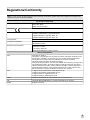
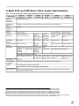
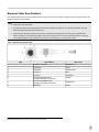
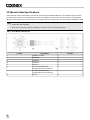
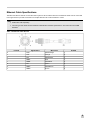
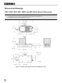
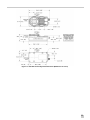
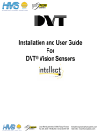
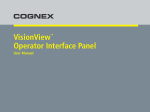
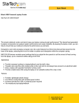
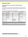
Addendum Sheet
In-Sight 5000 Series Vision System Installation Manual
Addendum
The In-Sight® 5000 series of vision systems now includes models with 128MB of non-volatile flash memory and 256MB
of image processing memory. This addendum includes hardware specifications to support these vision systems, along
with updates and corrections to existing legal notices, precautions and specifications. This information will be included in
the next revision of the In-Sight® 5000 Series Vision System Installation Manual. Please keep this addendum with your
installation manual.
The following In-Sight vision systems are supported with firmware version 4.4.3.
32MB non-volatile flash
memory
In-Sight Models
64MB non-volatile flash
memory
128MB non-volatile flash
memory1
5100, 5110
P/N 800-5870-1R
N/A
Type 821-0034-1R
5400, 5410
P/N 800-5855-1R
N/A
Type 821-0034-1R
5100C, 5400C
P/N 800-5837-4R
N/A
Type 821-0036-1R
5400R
P/N 800-5829-1R
N/A
N/A
5400S, 5410S
P/N 800-5855-3R
N/A
N/A
5400CS
P/N 800-5837-6R
N/A
N/A
5401, 5411
P/N 800-5838-4R
N/A
Type 821-0035-1R
5403, 5413
P/N 800-5830-4R
N/A
Type 821-0037-1R
5403S
P/N 800-5830-6R
N/A
N/A
5600, 5610
N/A
P/N 800-5871-1R
N/A
5603, 5613
N/A
P/N 800-5873-1R
N/A
5604, 5614
N/A
P/N 800-5874-1R
P/N 800-5874-2R
N/A
5605, 5615
N/A
N/A
Type 821-0032-1R
Note: This addendum does not include information for vision systems with 32MB or 64MB of memory. Models with
32MB and 64MB of memory can be identified by the Part Number (800-xxxx-xx). Models with 128MB of memory can
be identified by the Type number (821-xxxx-xx). To locate the Part Number or Type number, refer to the yellow label
affixed to the vision system.
1 Vision systems with 128MB of non-volatile flash memory cannot be downgraded below version 4.4.3 firmware.
1
Legal Notices
The software described in this document is furnished under license, and may be used or copied only in accordance with
the terms of such license and with the inclusion of the copyright notice shown on this page. Neither the software, this
document, nor any copies thereof may be provided to, or otherwise made available to, anyone other than the licensee.
Title to, and ownership of, this software remains with Cognex Corporation or its licensor. Cognex Corporation assumes
no responsibility for the use or reliability of its software on equipment that is not supplied by Cognex Corporation.
Cognex Corporation makes no warranties, either express or implied, regarding the described software, its
merchantability, non-infringement or its fitness for any particular purpose.
The information in this document is subject to change without notice and should not be construed as a commitment by
Cognex Corporation. Cognex Corporation is not responsible for any errors that may be present in either this document or
the associated software.
Companies, names, and data used in examples herein are fictitious unless otherwise noted. No part of this document
may be reproduced or transmitted in any form or by any means, electronic or mechanical, for any purpose, nor
transferred to any other media or language without the written permission of Cognex Corporation.
Cognex P/N 597-0133-01
Copyright © 2011 Cognex Corporation. All Rights Reserved.
Portions of the hardware and software provided by Cognex may be covered by one or more of the U.S. and foreign
patents listed below as well as pending U.S. and foreign patents. Such pending U.S. and foreign patents issued after the
date of this document are listed on Cognex web site at http://www.cognex.com/patents.
5481712, 5742037, 5751853, 5845007, 5909504, 5943441, 5949905, 5960125, 5978080, 5978081, 6005978,
6137893, 6141033, 6154567, 6215915, 6301396, 6327393, 6381375, 6408109, 6457032, 6490600, 6563324,
6658145, 6690842, 6771808, 6804416, 6836567, 6850646, 6856698, 6859907, 6920241, 6941026, 6959112,
6963338, 6975764, 6985625, 6993192, 7006712, 7016539, 7043081, 7058225, 7065262, 7069499, 7088862,
7107519, 7164796, 7175090, 7181066, 7251366, 7720315, JP 3927239
Cognex, In-Sight, EasyBuilder, VisionView, DataMan and DVT are registered trademarks of Cognex Corporation.
The Cognex logo, SmartLink, EdgeCount, FeatureCount, and ObjectLocate are trademarks of Cognex Corporation.
Windows is a registered trademark or trademark of Microsoft Corporation in the United States and other countries. Other
product and company trademarks identified herein are the trademarks of their respective owners.
2
Regulations/Conformity
Note: For the most up-to-date regulations and conformity information, please refer to the In-Sight online support site:
http://www.cognex.com/Support/InSight.
Declaration of Conformity
Cognex Corporation
One Vision Drive
Natick, MA 01760 USA
Manufacturer
Declares this
-marked Machine Vision System Product
Product Type
In-Sight 5100/5110/5400/5410: Type 821-0034-1R
In-Sight 5100C/5400C: Type 821-0036-1R
In-Sight 5401/5411: Type 821-0035-1R
In-Sight 5403/5413: Type 821-0037-1R
Complies With
2004/108/EC Electromagnetic Compatibility Directive
Compliance Standards
EN 55022:2006 +A1:2007
EN 61000-6-2:2005
European Representative
COGNEX INTERNATIONAL
Immeuble “Le Patio”
104 Avenue Albert 1er
92563 Rueil Malmaison Cedex - France
Safety and Regulatory
FCC
FCC Part 15, Class A
This device complies with Part 15 of the FCC Rules. Operation is subject to the
following two conditions: (1) this device may not cause harmful interference;
and (2) this device must accept any interference received, including
interference that may cause undesired operation.
This equipment generates, uses, and can radiate radio frequency energy and, if
not installed and used in accordance with the instruction manual, may cause
harmful interference to radio communications. Operation of this equipment in a
residential area is likely to cause harmful interference in which case the user
will be required to correct the interference at their own expense.
KCC
In-Sight 5100/5110/5400/5410: CGX-IS5400-01(A)
In-Sight 5100C/5400C: CGX-IS5400-C01(A)
In-Sight 5401/5411: CGX-IS5401-01(A)
In-Sight 5403/5413: CGX-IS5403-01(A)
NRTL
TÜV SÜD AM SCC/NRTL OSHA Scheme for UL/CAN 60950-1
CB
TÜV SÜD AM, IEC/EN 60950-1. CB report available upon request.
RoHS
RoHS 6 Compliant.
3
Precautions
Observe these precautions when installing In-Sight 5000 series vision systems to reduce the risk of injury or equipment
damage:
l
In-Sight 5000 series vision systems are intended to be supplied by a UL or NRTL listed power supply with a
24VDC output rated for at least 600 mA continuous and a maximum short circuit current rating of less than 8A and
a maximum power rating of less than 100VA and marked Class 2 or Limited Power Source (LPS). Any other
voltage creates a risk of fire or shock and can damage the In-Sight components.
l
Do not install In-Sight 5000 series vision systems where they are directly exposed to environmental hazards such
as excessive heat, dust, moisture, humidity, impact, vibration, corrosive substances, flammable substances, or
static electricity.
l
To reduce the risk of damage or malfunction due to over-voltage, line noise, electrostatic discharge (ESD), power
surges, or other irregularities in the power supply, route all cables and wires away from high-voltage power
sources.
l
The housing of the vision system is internally connected to the system ground wire (pin 8 of the Breakout cable).
Therefore, if the mounting surface of the vision system is at a non-zero ground potential, it is strongly
recommended that the vision system be mounted on an isolated or non-conductive mount.
l
Do not expose the CCD to laser light; CCDs can be damaged by direct, or reflected, laser light. If your application
requires the use of laser light that may strike the CCD, a lens filter at the corresponding laser's wavelength is
recommended. Contact your local integrator or application engineer for suggestions.
l
Do not open the In-Sight 5000 series vision system or remote head camera. These devices do not contain userserviceable parts.
l
Do not make electrical or mechanical modifications to In-Sight components. Unauthorized modifications may
violate your warranty.
l
Changes or modifications not expressly approved by the party responsible for regulatory compliance could void
the user’s authority to operate the equipment.
l
Cable shielding can be degraded or cables can be damaged or wear out more quickly if a bend radius or service
loop is tighter than 10X the cable diameter.
l
Service loops should be included with all cable connections.
l
4
This device is for business purposes and is qualified and registered for electromagnetic compatibility. The seller
or purchaser should be notified if you incorrectly purchased these products; please exchange them for home
use.
In-Sight 5100 and 5400 Series Vision System Specifications
Table 1-1: 5100, 5100C, 5401, 5400C, 5403 and 5400 Vision System Specifications
Specification
In-Sight
5100/5110
In-Sight
5100C
In-Sight
5401/5411
In-Sight
5400C
In-Sight
5403/5413
Minimum
Firmware
Requirement
In-Sight version 4.4.3
Job/Program
Memory
128MB non-volatile flash memory; unlimited storage via remote network device.
Image
Processing
Memory
256MB
Sensor
1/3-inch CCD
Sensor
Properties
5.92mm diagonal,
7.4 x 7.4µm sq. pixels
5.952mm
diagonal,
4.65 x 4.65µm
sq. pixels
Resolution
(pixels)
640 x 480
Electronic Shutter 16µs to 1000ms
Speed
Acquisition
In-Sight
5400/5410
1/1.8-inch CCD
1/3-inch CCD
5.92mm
diagonal,
7.4 x 7.4µm
sq. pixels
8.8mm diagonal,
4.4 x 4.4µm sq.
pixels
5.92mm diagonal,
7.4 x 7.4µm sq.
pixels
1024 x 768
640 x 480
1600 x 1200
640 x 480
32µs to
1000ms
16µs to
1000ms
27µs to 1000ms
16µs to 1000ms
Rapid reset, progressive scan, full-frame integration.
256 grey
levels (8
bits/pixel)
24 bit color
256 grey
levels (8
bits/pixel)
24 bit color
256 grey levels (8 bits/pixel)
60 full frames
per second.3
14 full frames per 60 full frames per
second.4
second.5
Gain/Offset controlled by software.
60 full frames per second.1
17 full frames
per second.2
Lens Type
C-mount
CCD Alignment
Variability6
±0.127mm (0.005in), (both x and y) from lens C-mount axis to center of imager.
Trigger
1 opto-isolated, acquisition trigger input.
Remote software commands via Ethernet and RS-232C.
Discrete Inputs
None built-in. Additional inputs available using a compatible I/O module. Unlimited inputs when
using an Ethernet I/O system.
1 Maximum frames per second is job-dependent and based on the minimum exposure for a full image frame capture.
2 Maximum frames per second are job dependent and based on an 8ms exposure and a full image frame capture.
3 Maximum frames per second is job-dependent and based on the minimum exposure for a full image frame capture.
4 Maximum frames per second is job-dependent and based on the minimum exposure for a full image frame capture.
5 Maximum frames per second is job-dependent and based on the minimum exposure for a full image frame capture.
6 Expected variability in the physical position of the CCD, from vision system-to-vision system. This equates to ~ ±17 pixels on a 640 x 480
resolution CCD, ~ ±27 pixels on a 1024 x 768 resolution sensor and ~ ±29 pixels on a 1600 x 1200 resolution CCD.
5
Specification
In-Sight
5100/5110
In-Sight
5100C
In-Sight
5401/5411
In-Sight
5400C
In-Sight
5403/5413
In-Sight
5400/5410
Discrete Outputs
2 built-in, high-speed outputs. Additional outputs available using a compatible I/O module. Unlimited
outputs when using an Ethernet I/O system.
Status LEDs
Power, Network Status, Network Traffic, 2 user configurable.
Network
Communication
1 Ethernet port, 10/100 BaseT, TCP/IP protocol. Supports DHCP (factory default) or static IP
address.
1588 Support
Timestamp Resolution: 8ns
Synchronization Accuracy Through Transparent Clock: 5µs
Serial
Communication
RS-232C when connected to a compatible I/O module.
Power (24VDC)
24VDC ±10%, 350mA maximum
Material
Die-cast aluminum housing.
Finish
Painted.
Mounting
Eight M4 threaded mounting holes (four front and four back).
Dimensions
83.4mm (3.28in) x 124.2mm (4.89in) x 61.4mm (2.42in) with lens cover installed.
43.5mm (1.71in) x 124.2mm (4.89in) x 61.4mm (2.42in) without lens cover installed (includes
Thread Guard).
Weight
350 g (12.3 oz.) Lens cover installed, without lens.
Operating
Temperature
0°C to 45°C (32°F to 113°F)
Storage
Temperature
–30°C to 80°C (22°F to 176°F)
Humidity
95%, non-condensing (Operating and Storage)
Protection
IP67 (with appropriate lens cover properly installed).
Shock
80 G Shock with 150 gram lens attached per IEC 68-2-27.
Vibration
10 G from 10-500 Hz with 150 gram lens per IEC 68-2-6.
Regulatory
Compliance
CE, FCC, KCC, TÜV SÜD NRTL, RoHS
6
24VDC ±10%,
24VDC ±10%,
500mA maximum. 350mA maximum.
Breakout Cable Specifications
The 24VDC Breakout connector provides access to power, serial communications, trigger and high-speed outputs. The
Breakout cable is not terminated.
Note:
l
Cables are sold separately.
l
Unused bare wires can be clipped short or tied back using a tie made of non-conductive material. Keep all
bare wires separated from the +24VDC wire.
l
The housing of the vision system is internally connected to the system ground wire (pin 8 of the Breakout
cable). Therefore, if the mounting surface of the vision system is at a non-zero ground potential, it is strongly
recommended that the vision system be mounted on an isolated or non-conductive mount.
Table 1-2: Breakout Cable Pin-Out
Pin#
Signal Name
Wire Color
1
POWER, +24 VDC
White/Green
2
TRIGGER+
Green
3
TRIGGER-
White/Orange
4
HS OUT 0
Blue
5
HS OUT 1
White/Blue
(RxD)1
6
RS-232 RECEIVE
(In-Sight 5604 Only: Encoder A)
Orange
7
RS-232 TRANSMIT (TxD)2
(In-Sight 5604 Only: Encoder B)
White/Brown
8
GROUND
Brown
1 If hardware handshaking is required, an I/O module must be used.
2 If hardware handshaking is required, an I/O module must be used.
7
I/O Module Cable Specifications
The I/O Module cable is used with the optional I/O module and 1350 Breakout Module. The I/O Module cable connects
the vision system directly to the applicable I/O module via the DB15 connector. When the I/O module or 1350 Breakout
Module is used, all power and communication lines used by the vision system are connected using the I/O Module cable.
Note:
l
Cables are sold separately.
l
Refer to your specific I/O module installation manual for more connection information.
Table 1-3: I/O Module Cable Pin-Out
P1 Pin#
Signal Name
P2 Pin#
1
POWER, +24 VDC
1
2
TRIGGER+
2
3
TRIGGER-
3
4
HS OUT 0
4
5
HS OUT 1
5
6
RS-232 RECEIVE (RxD)
(In-Sight 5604 Only: Encoder A)
6
7
RS-232 TRANSMIT (TxD)
(In-Sight 5604 Only: Encoder B)
7
8
Ground
8
8
Ethernet Cable Specifications
The Ethernet cable is used to connect the vision system to other network devices. The Ethernet cable can be connected
to a single device or provide connections to multiple devices via a network switch or router.
Note:
l
Cables are sold separately.
l
The wiring for this cable follows standard industrial Ethernet M12 specifications. This varies from the 568B
standard.
Table 1-4: Ethernet Cable Pin-Out
P1 Pin#
Signal Name
Wire Color
P2 Pin#
6
TPO+
White/Orange
1
4
TPO-
Orange
2
5
TPI+
White/Green
3
7
TRMA
Blue
4
1
TRMB
White/Blue
5
8
TPI-
Green
6
2
TRMC
White/Brown
7
3
TRMD
Brown
8
9
Dimensional Drawings
5100, 5100C, 5400, 5401, 5400C and 5403 Vision System Dimensions
Note:
l
All dimensions are in millimeters [inches] and are for reference purposes only.
l
All specifications may be changed without notice.
Figure 1-1: Standard Vision System Dimensions (With Lens Cover)
10
Figure 1-2: Standard Vision System Dimensions (Without Lens Cover)
11
P/N 597-0133-01
Printed in the USA