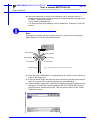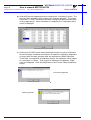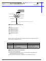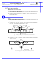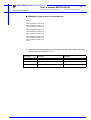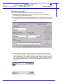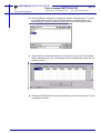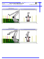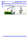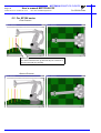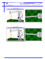
1
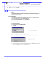
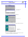
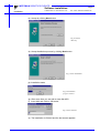
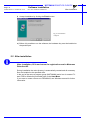
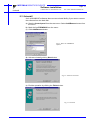
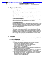
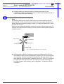
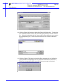
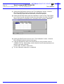
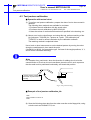
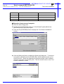
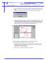
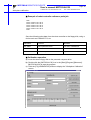
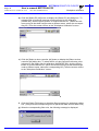
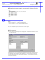
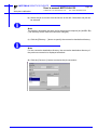
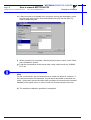
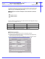
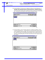
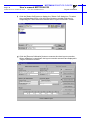
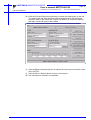
MOTOMAN
MOTOMAN XRC
USER’S MANUAL
MOTOCALV32
Upon receipt of the product and prior to initial operation, read these instructions thoroughly,
and retain for future reference.
MOTOMAN ROBOTICS EUROPE
A subsidiary of YASKAWA Electric Corporation
MANUAL NO. MRS55040
MOTOMAN ROBOTICS EUROPE
Reference list
Operator’s Manual - User Functions
Operator’s Manual - Basic Programming
Instruction Manual for robot
Revision
991124
First release of this manual
MOTOMAN ROBOTICS EUROPE
User’s manual MOTOCALV32
Created: 99-11-23 Revised: 99-11-23
Page: 3
Doc. name: Mrs55040TOC.fm
1. General information .............................................. 5
Outline of MOTOCALV32
❏ Requirements for MOTOCALV32 execution
5
5
2. Software installation ............................................. 7
Installation
After installation
Uninstall
7
10
11
3. Types of calibration ............................................ 13
❏
❏
❏
❏
❏
Robot calibration
Tool calibration
Tool posture calibration
Workpiece calibration
Layout correction
13
13
13
13
13
4. Operation ............................................................ 13
Robot calibration
❏ Operation with actual robot
❏ Example of robot calibration job
❏ Operation from personal computer
Tool calibration
❏ Operation with actual robot
❏ Example of tool calibration job
❏ Operation from personal computer
Tool posture calibration
❏ Operation with actual robot
❏ Example of tool posture calibration job
❏ Operation from personal computer
Workpiece calibration
❏ Virtual job (non existing system)
❏ Example of personal computer reference point job
❏ Actual job (existing system)
❏ Example of robot controller reference point job
❏ Calibration operation
❏ Example of personal computer reference
point job after calibration
❏ Job conversion
Layout correction
❏ Virtual correction (non existing system)
❏ Robot layout correction:
Example of personal computer reference point job
❏ Actual correction (existing system)
❏ Robot layout correction:
Example of robot controller reference point job
❏ Calibration operation
Travel axis correction
❏ Operation with actual robot
❏ <Example of travel axis tilt correction job
❏ Calibration operation
13
13
15
16
21
21
22
22
25
25
25
26
28
28
28
28
29
29
32
32
35
35
35
35
36
36
40
40
41
42
5. Appendix-1 Examples of robot calibration .......... 47
For SK and SV series
For SP100 series
For SP70 series
47
50
53
MOTOMAN ROBOTICS EUROPE
Page: 4
User’s manual MOTOCALV32
Created: 99-11-23 Revised: 99-11-23
Doc. name: Mrs55040TOC.fm
6. Appendix-2 Examples of tool calibration ............ 56
For SK and SV series
For SP100 series
For SP70 series
56
60
64
MOTOMAN ROBOTICS EUROPE
User’s manual MOTOCALV32
Outline of MOTOCALV32
Created: 99-11-23 Revised: 99-11-23
Page: 5
Doc. name: Mrs55040-ch1.fm
MOTOCALV32
Motoman part number: 441104-80 (English version only)
This manual is valid for version: 4.52 and up.
Valid for ERC, MRC and XRC.
MOTOCALV32 does not include file transfer function.
1. General information
Diagrams and photos in this manual are used as examples only and may differ
from the actual delivered product.
This manual may be modified when necessary because of improvement of the
product, modification, or changes in specifications.
Such modification is made as a revision by renewing the manual No.
To order a copy of this manual, if your copy has been damaged or lost, contact
your YASKAWA representative listed on the last page stating the manual No. on
the front page.
YASKAWA is not responsible for any modification of the product made by the user
since that will void our guarantee.
Software supplied with this manuals intended for use by licensed operators only
and may only be used or copied according to the provisions of the license.
Reproduction of any part of this manual without the consent of YASKAWA is forbidden.
1.1 Outline of MOTOCALV32
The MOTOCALV32 has been developed to improve positioning accuracy of YASKAWA’s industrial robot MOTOMAN. The MOTOCALV32 is an application software for MS-Windows, which offers excellent operability on various types of
personal computers.
■ Requirements for MOTOCALV32 execution
OS
MS-Windows 95/98/NT4.0 *
Required Memory
16 Mbytes or more
CPU
Pentium 90 MHz or more
Hardware disk
Capacity
15 Mbytes or more
Screen
Screen supported by Windows (256 colors or more)
Mouse
Mouse supported by Windows
* MS-Windows95, MS-Windows98, MS-Windows NT4.0 are trade marks of Microsoft Corporation, U.S.A.
MOTOMAN ROBOTICS EUROPE
Page: 6
User’s manual MOTOCALV32
Created: 99-11-23 Revised: 99-11-23
Doc. name: Mrs55040-ch1.fm
Outline of MOTOCALV32
MOTOMAN ROBOTICS EUROPE
Software installation
Installation
Created: 96-01-31 Revised: 99-11-23
Page: 7
Doc. name: Software-installation.fm
2. Software installation
Note
This chapter shows a general installation phase of any software. In this example
the software FDDWIN is installed. Select the right software by choosing the
appropriate software name.
2.1 Installation
There are three ways to start installation of this software, all will give the same
result. The most common way is described below.
a) Put the first diskette named #1 in the disk-drive.
b) Click on the Start button on the menu-bar.
c) Choose Run from the menu.
d) Browse to drive A:\
e) Choose the file named SETUP.EXE
f) Click OK.
Fig.1 Choose installation file
g) Choose OK and the installation guide will start.
h) You can quit the installation att any time by clicking the Cancel-button and
then confirm by Yes-button.
Fig.2 You can cancel
installation at any time
i) Mark the language you want to use during installation. Note! This will not influence the language you use in FDDWIN32 later.
MOTOMAN ROBOTICS EUROPE
Software installation
Page: 8
Created: 96-01-31 Revised: 99-11-23
Installation
Doc. name: Software-installation.fm
j) Click on the OK-button.
Fig.3 Language selection
during installation
k) Pass this information screen by clicking the Next-button.
Fig.4 Information screen
l) Read through the license agreement and accept by clicking on the Next-button.
Fig.5 License
agreement. Accept by
clicking Next.
m) Set directory for FDDWIN32. It’s advisable to install the software in the directory which is set as default by the installation guide.
MOTOMAN ROBOTICS EUROPE
Software installation
Installation
Created: 96-01-31 Revised: 99-11-23
Page: 9
Doc. name: Software-installation.fm
n) Accept by clicking Next-button.
Fig.6 Choose
directory
o) Accept installation process by clicking Next-button.
Fig.7 Start installation
p) Installation starts.
Fig.8 Installation
progress counter
q) After some time you are told to enter disk #2/2.
r) Insert disk and click on OK-button.
Fig.9 Insert disk #2
s) The installation is finished and the last screen appears.
MOTOMAN ROBOTICS EUROPE
Software installation
Page: 10
Created: 96-01-31 Revised: 99-11-23
After installation
Doc. name: Software-installation.fm
t) Accept installation by clicking the Finish-button.
Fig.10 Installation
complete
u) Before it is possible to run the software, the hardware key must be installed on
the parallel port.
2.2 After installation
After installation, fill in and return the registration card to Motoman
Robotics AB.
During installation the main directory is automatically created and all necessary
files are installed in the specified drive.
In the end of the setup a program group (MOTOMAN) and a icon is created. To
start FDD for Windows just double-click on the Start Menu.
If you want to create a shortcut to FDDWIN32, see Windows manual for further
information
MOTOMAN ROBOTICS EUROPE
Software installation
Uninstall
Page: 11
Created: 96-01-31 Revised: 99-11-23
Doc. name: Software-installation.fm
2.3 Uninstall
As in all WIN95/NT softwares there are an uninstall facility if you want to remove
the software from the hard disk.
a) Start the Control panel from the start menu. Select Add/Remove button from
the menu.
b) Mark the line FDDWIN32 from the menu.
c) Click Add/Remove button.
Fig.11 Mark the FDDWIN32
software
d) Activate uninstall guide by Next-button.
Fig.12 Automatic uninstall
e) End the operation by clicking the Finish-button.
Fig.13 Uninstall
MOTOMAN ROBOTICS EUROPE
Page: 12
Created: 96-01-31 Revised: 99-11-23
Software installation
Doc. name: Software-installation.fm
Uninstall
MOTOMAN ROBOTICS EUROPE
User’s manual MOTOCALV32
Robot calibration
Created: 99-11-23 Revised: 99-11-23
Page: 13
Doc. name: Mrs55040-ch3.fm
3. Types of calibration
The following types of calibrations are available for MOTOCALV32.
■ Robot calibration
Adjusts the absolute data and tool data, by teaching 5 postures each of 5 points
(total 25 points) with robot. This calibration improves the absolute value accuracy
of robot.
■ Tool calibration
Adjusts tool data by teaching 7 postures at 1 point (total 7 points) with robot. This
calibration calculates the exact tool data (robot control point).
■ Tool posture calibration
Adjusts tool data by teaching 1 posture at 1 point (total 1 point) with robot. This
calibration calculates the exact tool positions (Rx, Ry, and Rz).
■ Workpiece calibration
Recognizes the positional difference between each robot and workpiece, by comparing the job created by offline system and the job created with the actual robot.
Then converts the position data by offline system into the data for the actual
robot, using the difference above.
■ Layout correction
The layout correction is composed of "Robot Layout Correction" and "Travel Axis
Tilt Correction." "Robot Layout Correction" corrects the robot layout in the cell
constructed by ROTSY for actual robot layout, by comparing the job created by
offline system and the job created with the actual robot. "Travel Axis Tilt Correction" corrects the robot layout in the cell constructed by ROTSY for the actual
robot layout, by calculating the positional difference between the travel axis and
the robot positioned on the travel axis.
4. Operation
This chapter explains the operation method of each calibration by MOTOCALV32.
4.1 Robot calibration
■ Operation with actual robot
1) To perform robot calibration, prepare the data of tool to be mounted in
advance.
The following three methods are available for tool data.
•Performs the tool calibration with the actual robot controller.
‚Performs the tool calibration by MOTOCALV32.
(Refer to Section 2.2 "Tool Calibration.")
ƒUses the values of mechanical dimensions if specified in the drawing, etc.
2) Mount an end-pointed tool on the robot flange.
Use a tool with pointed-end part offset to the direction of X- or Y-axis on the
tool coordinate. (Offset amount of approx. 200 mm is recommended.)
3) Using this tool, perform teaching of the job (job name: ROBOT) for 5 postures
each of 5 points (total 25 points). The calibration job "ROBOT" is used for
actual calculation by the calibration software.
The teaching method is explained below.
MOTOMAN ROBOTICS EUROPE
Page: 14
User’s manual MOTOCALV32
Created: 99-11-23 Revised: 99-11-23
Doc. name: Mrs55040-ch3.fm
Robot calibration
a) Using the same tool, perform teaching of 5 postures at each 5 point.
(Use MOVJ or MOVL for interpolation type. On base of the taught positions, X,
Y, and Z will be calculated internally.)
Note
For teaching of large-size robots of K60 and more, perform teaching with the
wrist angle 45° or less, since the flexure by the robot arm weight may affect calibration, with the wrist posture largely inclined. For robot sizes below K60, incline
the wrist 45° or more.
When the actual playback operation requires movement changing robot form, for
example, the robot wrist axis rotating in reverse, perform teaching with the posture
of that movement.
Robot
1:st posture
5:th posture
3:rd posture
2:nd posture
4:th posture
Positioning jig
Fig.1 Teaching the same point with 5 postures
b) With operation a), perform teaching of 1 point at 5 different points (The distance between each point should be kept to a minimum of 100 mm horizontally
and vertically). Perform teaching at five points from left upper side to right
lower side with 5 postures each, so that the values of X, Y, and Z vary equally
in a wide area of the robot front face, for teaching of correct calibration job.
For robot postures at job teaching, refer to Appendix 1 "Examples of Robot
Calibration."
MOTOMAN ROBOTICS EUROPE
User’s manual MOTOCALV32
Robot calibration
Created: 99-11-23 Revised: 99-11-23
Page: 15
Doc. name: Mrs55040-ch3.fm
■ Example of robot calibration job
NOP
*1
MOVJ C0000 VJ=0.78 PL=0
MOVJ C0001 VJ=0.78 PL=0
MOVJ C0002 VJ=0.78 PL=0
MOVJ C0003 VJ=0.78 PL=0
MOVJ C0004 VJ=0.78 PL=0
*2
MOVJ C0005 VJ=0.78 PL=0
MOVJ C0006 VJ=0.78 PL=0
MOVJ C0007 VJ=0.78 PL=0
MOVJ C0008 VJ=0.78 PL=0
MOVJ C0009 VJ=0.78 PL=0
*3
MOVJ C0010 VJ=0.78 PL=0
MOVJ C0011 VJ=0.78 PL=0
MOVJ C0012 VJ=0.78 PL=0
MOVJ C0013 VJ=0.78 PL=0
MOVJ C0014 VJ=0.78 PL=0
*4
MOVJ C0015 VJ=0.78 PL=0
MOVJ C0016 VJ=0.78 PL=0
MOVJ C0017 VJ=0.78 PL=0
MOVJ C0018 VJ=0.78 PL=0
MOVJ C0019 VJ=0.78 PL=0
*5
MOVJ C0020 VJ=0.78 PL=0
MOVJ C0021 VJ=0.78 PL=0
MOVJ C0022 VJ=0.78 PL=0
MOVJ C0023 VJ=0.78 PL=0
MOVJ C0024 VJ=0.78 PL=0
END
Positioning jigs
P5
Robot
P4
P3
P2
P1
Fig.2 Teaching 5 points with 5 postures
Save the following robot data from the robot controller to the floppy
disk, using a device such as YASNAC FC2, etc.
File Name
Contents
Remarks
ALL.PRM
Robot parameter data
For ERC, PARAM.DAT
ABSO.DAT
Robot absolute data
TOOL.CND
Tool data
ROBOT.JBI
Job of 5 postures each at 5 points
for calibration
For ERC, TOOL.DAT
MOTOMAN ROBOTICS EUROPE
Page: 16
User’s manual MOTOCALV32
Created: 99-11-23 Revised: 99-11-23
Doc. name: Mrs55040-ch3.fm
Robot calibration
■ Operation from personal computer
a) Insert the above floppy disk.
b) Double-click the [MOTOCALV32] icon in the [Start]-[Program]-[Motoman][MOTOCALV32] to start the program. The main screen, "MOTOCALV for
Windows95" is displayed for calibration programs.
c) Click the [F1] (ROBOT) button to display the "Robot Calibration" screen.
d) Click the [Select Job] button to display the [Select Job] dialog box. To select
the robot calibration job file (Robot.JBI), click the [Open] button or double-click
the file. (When the calibration job has been taught under a different job name,
select the corresponding file.) Then the screen returns to the "Robot Calibration" screen.
MOTOMAN ROBOTICS EUROPE
User’s manual MOTOCALV32
Robot calibration
Created: 99-11-23 Revised: 99-11-23
Page: 17
Doc. name: Mrs55040-ch3.fm
e) Click the [Select Robot] button to display the [Select Robot] dialog box. To
select the robot type for robot calibration, click the [OK] button or double-click
the corresponding type. If the corresponding type of robot is not on the list,
select the "other robot type." Then the screen returns to the "Robot Calibration" screen.
f) Click the [Check File] button to check the files necessary for calibration.
(Verify that the corresponding files for parameter data, absolute data and tool
data exist.)
When the corresponding files exist, the following message is displayed.
g) Click the [OK] button to return to the "Robot Calibration" screen. Click the
[Execute Calibration] button to display the "Calculation" screen. Then calibration starts and the calculation process is displayed.
h) Clicking the [STOP] button stops the calculation to return to the "Robot Calibration" screen and the calculation result will not be written in the file (ABSO
Data, TOOL Data).
MOTOMAN ROBOTICS EUROPE
Page: 18
User’s manual MOTOCALV32
Created: 99-11-23 Revised: 99-11-23
Doc. name: Mrs55040-ch3.fm
Robot calibration
i) When calculation is completed, the "Calculation finish" screen is displayed.
j) Click the [EXIT] button and the calibration will be judged as "successful" or "failed" based on the average error (theoretical value by calibration calculation).
Then 2 types of "Message of Calibration Judgement" are displayed.
k) Click the [OK] button to return to the "Robot Calibration" screen.
Successfull calibration
Failed calibration
Note
When a message for failed calibration is displayed, perform re-teaching of robot
calibration from the step 3) and re-execute the process.
For some failed calibration jobs or robot types after re-teaching and re-executing
the process, extend the calculation range for calibration job. For calculation range
setting, contact your YASKAWA representative or YASKAWA Robot Service.
l) Click the [OK] button to return to the "Robot Calibration" screen. When a successful calibration result is obtained, stop the operation on personal computer
once, and load the changed ABSO Data and TOOL Data to the actual robot,
by using a device such as YASNAC FC2, etc.
(ABSO.DAT, TOOL.CND. For ERC, ABSO.DAT, TOOL.DAT)
After verifying that new ABSO Data and TOOL Data have been overwritten in the
robot controller, turn OFF power to the robot controller and re-start.
MOTOMAN ROBOTICS EUROPE
User’s manual MOTOCALV32
Robot calibration
Created: 99-11-23 Revised: 99-11-23
Page: 19
Doc. name: Mrs55040-ch3.fm
m) Using the same tool as used for the calibration job (5 postures each at 5
points), perform teaching of the control point constant operation job (job name:
P7-NEW, 7 postures at 1 point).
This is called a judgement job.
For robot postures at job teaching, refer to Appendix 2 "Example of Tool Calibration."
Note
This operation checks how much robot accuracy is improved by changing the
ABSO Data and TOOL Data by calibration job.
Robot
1:st posture
5:th posture
6:th posture
7:th posture
Positioning jig
2:nd posture
3:rd posture
4:th posture
Fig.3 Teaching the same point with 7 postures
n) Save the job (P7-NEW.JBI) of 7 taught postures at 1 point, from the robot controller to the floppy disk.
o) Insert the above floppy disk from the robot controller to the personal computer
drive, and execute the continued operation for robot calibration.
p) Click the [Select Judgement-Job] button to display the [Select Judgement-Job]
dialog box. To select the created judgement job file (P7-NEW.JBI), click the
[Open] button or double-click the file. Then the screen returns to the "Robot
Calibration" screen.
MOTOMAN ROBOTICS EUROPE
Page: 20
User’s manual MOTOCALV32
Created: 99-11-23 Revised: 99-11-23
Doc. name: Mrs55040-ch3.fm
Robot calibration
q) Click the [Execute Judgement] button to display the "Calculating" screen. The
accuracy after calibration of the control point constant operation. The screen
shows the X, Y, and Z coordinates and their average coordinates at each point
of the judgement job. When calculation is completed, the "Calculation finish"
screen is displayed.
r) Clicking the [CLOSE] button starts checking the maximum values of distance
from the average coordinate to each point, and performs calibration judgement
of control point constant operation after the adjustment of ABSO Data and
TOOL Data. At completion of calibration process, the calibration will be judged
as "successful" or "failed." Then 2 types of "Message of Calibration Judgement" are displayed. Click the [OK] button to return to the "Robot Calibration"
screen.
Successful judgement
Failed judgement
MOTOMAN ROBOTICS EUROPE
User’s manual MOTOCALV32
Tool calibration
Created: 99-11-23 Revised: 99-11-23
Page: 21
Doc. name: Mrs55040-ch3.fm
Note
When a failed judgement result message is displayed, perform re-teaching of calibration from step m).
s) Click the [OK] button to return to the "Robot Calibration" screen. When a successful judgement message is displayed, click the [Print a Report] button to
print out the report. The robot calibration operation is completed.
4.2 Tool calibration
■ Operation with actual robot
1) To perform tool calibration, prepare the data of tool to be mounted in advance.
Mount the tool on the robot flange. The following two methods are available
for tool data, in addition to tool calibration method explained in this section.
• Performs the tool calibration with the actual robot.
‚Uses the values of mechanical dimensions of the tool if specified in the drawing, etc.
2) Using this tool, perform teaching of the job (job name: TOOL) of 7 postures
and more at 1 point. The calibration job "TOOL" is used for actual calculation
by the calibration software.
The teaching method is explained below.
a) Using the same tool, perform teaching of 7 postures at one point.
(Use MOVJ or MOVL for interpolation type. On base of the taught positions,
X, Y, and Z will be calculated internally.)
Note
For teaching of large-size robots of K60 and more, perform teaching with the wrist
angle 45° or less, since the flexure by the robot arm weight may affect calibration,
with the wrist posture largely inclined. For robot sizes below K60, incline the wrist
45° or more.
When the actual playback operation requires movement as changing robot form,
for example, the robot wrist axis rotating in reverse, perform teaching with the
posture of that movement. For robot postures at job teaching, refer to Appendix 2
"Examples of Tool Calibration."
MOTOMAN ROBOTICS EUROPE
Page: 22
User’s manual MOTOCALV32
Created: 99-11-23 Revised: 99-11-23
Tool calibration
Doc. name: Mrs55040-ch3.fm
Robot
1:st posture
5:th posture
2:nd posture
3:rd posture
6:th posture
7:th posture
Positioning jig
4:th posture
Fig.4 Teaching the same point with 7 postures
■ Example of tool calibration job
NOP
MOVJ C000 VJ=0.78 PL=0
MOVJ C001 VJ=0.78 PL=0
MOVJ C002 VJ=0.78 PL=0
MOVJ C003 VJ=0.78 PL=0
MOVJ C004 VJ=0.78 PL=0
MOVJ C005 VJ=0.78 PL=0
MOVJ C006 VJ=0.78 PL=0
END
Save the following robot data from the robot controller to the floppy disk, using a
device such as YASNAC FC2, etc.
File Name
Contents
Remarks
ALL.PRM
Robot parameter data
For ERC, PARAM.DAT
TOOL.CND
Tool data
For ERC, TOOL.DAT
TOOL.JBI
Job for tool calibration
7 postures or more at 1 point
■ Operation from personal computer
a) Insert the above floppy disk.
b) Double-click the [MOTOCALV32] icon in the [Start]-[Program]-[Motoman][MOTOCALV32] to start the program.
c) Click the [F2] (TOOL) button to display the "Tool Calibration" screen.
MOTOMAN ROBOTICS EUROPE
User’s manual MOTOCALV32
Tool calibration
Created: 99-11-23 Revised: 99-11-23
Page: 23
Doc. name: Mrs55040-ch3.fm
d) Click the [Select job] button to display the [Select job] dialog box. To select the
tool calibration job file (TOOL.JBI), click the [Open] button or double-click the
file. (When the calibration job has been taught under a different name, select
the corresponding file.) Then the screen returns to the "Robot Calibration"
screen.
e) Click the [Check File] button to check the files necessary for tool calibration.
(Verify that the corresponding files for parameter data and tool data exist.)
When the corresponding files exist, the following message is displayed.
MOTOMAN ROBOTICS EUROPE
Page: 24
User’s manual MOTOCALV32
Created: 99-11-23 Revised: 99-11-23
Doc. name: Mrs55040-ch3.fm
Tool calibration
f) Clicking the [OK] button returns to the "Tool Calibration" screen. Click the
[Execute Calibration] button to display the "Calculating" screen.
Then calibration starts and the calculation process is displayed.
g) Clicking the [STOP] button stops the calculation to return to the "Tool Calibration" screen and the calculation result will not be written in the file (Tool Data).
When calculation is completed, the "Calculation finish" screen is displayed.
h) Clicking the [EXIT] button returns to the "Tool Calibration" screen. Click the
[Print a Report] button to print out the report.
i) Load the changed tool data to the actual robot, by using a device such as
YASNAC FC2, etc. After loading, confirm that the new tool data has been overwritten in the robot controller.
(TOOL.CND. For ERC, TOOL.DAT)
j) The tool calibration operation is completed.
MOTOMAN ROBOTICS EUROPE
User’s manual MOTOCALV32
Tool posture calibration
Created: 99-11-23 Revised: 99-11-23
Page: 25
Doc. name: Mrs55040-ch3.fm
4.3 Tool posture calibration
■ Operation with actual robot
1) To perform tool posture calibration, prepare the data of tool to be mounted in
advance.
The following three methods are available for tool data.
• Performs the tool calibration with the actual robot.
‚ Performs the tool calibration by MOTOCALV32.
ƒ Uses the values of mechanical dimensions if specified in the drawing, etc.
2) Mount a tool on the robot flange, and using this tool, perform teaching of the
job (job name: TOOLPS) for 1 posture at 1 point. This calibration job
"TOOLPS" is used for actual calculation by the calibration software.
The teaching method is explained below.
Use a level or other instruments to set the desired posture by moving the robot
along the coordinate axis, then teach the point.
(Use MOVJ or MOVL for interpolation type. On base of the taught positions, X, Y,
and Z will be calculated internally.)
Note
For example of arc weld torch, when the direction of welding wire is to be the
same direction of Z-axis on the tool coordinate, place the tool in such a posture
that the weld torch is positioned horizontally, and teach this position.
Set the posture so that the
weld torch is positioned horizontally.
Fig.5 One point teaching
■ Example of tool posture calibration job
NOP
MOVJ C000 VJ=0.78 PL=0
END
3) Save the following robot data from the robot controller to the floppy disk, using
a device such as YASNAC FC2, etc.
MOTOMAN ROBOTICS EUROPE
Page: 26
User’s manual MOTOCALV32
Created: 99-11-23 Revised: 99-11-23
Doc. name: Mrs55040-ch3.fm
Tool posture calibration
File Name
Contents
Remarks
ALL.PRM
Robot parameter data
For ERC, PARAM.DAT
TOOL.CND
Tool data
For ERC, TOOL.DAT
TOOLPS.JBI
Job for tool posture calibration
1 posture at 1 point
■ Operation from personal computer
a) Insert the above floppy disk.
b) Double-click the [MOTOCALV32] icon in the [Start]-[Program]-[Motoman][MOTOCALV32] to start the program.
c) Click the [F3] (POSTURE) button to display the "Tool Posture Calibration"
screen.
d) Click the [Select job] button to display the [Select job] dialog box. To select the
tool posture calibration job file (TOOLPS.JBI), click the [Open] button or double-click the file. (When the calibration job has been taught under a different
job name, select the corresponding file.) Then the screen returns to the "Tool
Posture Calibration" screen.
MOTOMAN ROBOTICS EUROPE
User’s manual MOTOCALV32
Tool posture calibration
Created: 99-11-23 Revised: 99-11-23
Page: 27
Doc. name: Mrs55040-ch3.fm
e) Click the [Check File] button to check the files necessary for tool posture calibration. (Verify that the corresponding files for parameter data and tool data
exist.)
When the corresponding files exist, the following message is displayed.
f) Click the [OK] button to return to the "Tool Posture Calibration" screen. Click
the [Define tool posture] button to display the "Tool Posture Settings" screen.
Then click the [Rx-], [Rx+], [Ry-], [Ry+], [Rz-], and [Rz+] buttons as many
times as needed, to set the taught posture with actual robot. Then click the
[OK] button to return to the "Tool Posture Calibration" screen.
g) Click the [Execute Calibration] button to execute the calibration.
h) Click the [Print a Report] button to print out the report.
i) Load the changed tool data to the actual robot, by using a device such as
YASNAC FC2, etc. After loading, confirm that the new tool data has been
overwritten in the robot controller.
(TOOL.CND. For ERC, TOOL.DAT)
j) The tool posture calibration operation is completed.
MOTOMAN ROBOTICS EUROPE
Page: 28
User’s manual MOTOCALV32
Created: 99-11-23 Revised: 99-11-23
Doc. name: Mrs55040-ch3.fm
Workpiece calibration
4.4 Workpiece calibration
The workpiece calibration is composed of "Workpiece calibration" and "Job conversion." "Workpiece calibration" calculates the positional difference between
each robot and workpiece, by comparing the job created by offline system and the
job created with the actual robot. Then "Job conversion" converts the position data
by offline system into the data for the actual robot, using the difference above.
■ Virtual job (non existing system)
Teaching of personal computer reference point teaching job
Perform teaching of personal computer reference point teaching job by ROTSY.
Job name: WORK
Teaching method:
Using the same tool, teach the workpiece reference points. Decide 3 or more reference points. (5 points are recommended. When higher accuracy is required,
teach more points.) Teach the first 3 points to form a triangle largely covering the
robot working envelope for the workpiece. The order of teaching and number of
teaching points should be the same as for the robot controller reference point
teaching job explained in "n Teaching of robot controller reference point teaching
job (Operation with actual robot)" below. For interpolation type, use MOVJ or
MOVL. On base of the taught positions, X, Y, and Z will be calculated internally. (It
is recommended that reference point teaching be performed without changing the
robot posture, to maintain accuracy of tool data (robot control point)).
■ Example of personal computer reference point job
NOP
MOVL C0000 V=46.0 PL=0
MOVL C0001 V=46.0 PL=0
MOVL C0002 V=46.0 PL=0
MOVL C0003 V=46.0 PL=0
MOVL C0004 V=46.0 PL=0
END
■ Actual job (existing system)
Teaching of robot controller reference point teaching job (Operation with actual
robot)
Perform teaching of robot controller reference point teaching job with actual robot.
Job name: WORKREF
Teaching method:
Using the same tool, teach the workpiece reference points. Decide 3 or more
reference points. (5 points are recommended. When higher accuracy is required,
teach more points.) Teach the first 3 points to form a triangle largely covering the
robot working envelope for the workpiece. The order of teaching and number of
teaching points should be the same as for the personal computer reference point
teaching job explained in "Teaching of personal computer reference point teaching
job" in the previous page. Any interpolation type can be used. (For teaching reference points, it is recommended that reference point teaching be performed without changing the robot posture to maintain accuracy of tool data (robot control
point)).
MOTOMAN ROBOTICS EUROPE
User’s manual MOTOCALV32
Workpiece calibration
Created: 99-11-23 Revised: 99-11-23
Page: 29
Doc. name: Mrs55040-ch3.fm
■ Example of robot controller reference point job
NOP
MOVL C0000 V=46.0 PL=0
MOVL C0001 V=46.0 PL=0
MOVL C0002 V=46.0 PL=0
MOVL C0003 V=46.0 PL=0
MOVL C0004 V=46.0 PL=0
END
Save the following robot data from the robot controller to the floppy disk, using a
device such as YASNAC FC2, etc.
File Name
Contents
Remarks
ALL.PRM
Robot parameter data
For ERC, PARAM.DAT
TOOL.CND
Tool data
For ERC, TOOL.DAT
WORKREF.JBI
Job for workpiece calibration
3 points or more
■ Calibration operation
a) Insert the above floppy disk to the personal computer drive.
b) Double-click the [MOTOCALV32] icon in the [Start]-[Program]-[Motoman][MOTOCALV32] to start the program.
c) Click the [F4] (WORKPIECE) button to display the "Workpiece Calibration"
screen.
MOTOMAN ROBOTICS EUROPE
Page: 30
User’s manual MOTOCALV32
Created: 99-11-23 Revised: 99-11-23
Doc. name: Mrs55040-ch3.fm
Workpiece calibration
d) Click the [Select PC job] button to display the [Select PC job] dialog box. To
select the file of personal computer reference point job for calibration
(WORK.JBI), click the [Open] button or double-click the file. (When the reference point job has been taught under a different name, select the corresponding file.) Then the screen returns to the "Workpiece Calibration" screen.
e) Click the [Select a robot controller job] button to display the [Select a robot
controller job] dialog box. To select the file of robot controller reference point
job saved in the floppy disk for calibration (WORKREF.JBI), click the [Open]
button or double-click the file. (When the reference point job has been taught
under a different name, select the corresponding file.) Then the screen returns
to the "Workpiece Calibration" screen.
f) Click the [Check File] button to check the files necessary for workpiece calibration. (Verify that the corresponding files for parameter data and tool data exist.)
g) When the corresponding files exist, the following message is displayed.
MOTOMAN ROBOTICS EUROPE
User’s manual MOTOCALV32
Workpiece calibration
Created: 99-11-23 Revised: 99-11-23
Page: 31
Doc. name: Mrs55040-ch3.fm
h) Click the [OK] button to return to the "Workpiece Calibration" screen.
Note
If no comment is required, it is not necessary to write in.
i) Click the [Execute Calibration] button to display the "Calculating" screen.
Input a comment to be written in the personal computer job (WORK.JBI).
Then calibration starts and the calculation process is displayed.
Note
As calculation result, the conversion constant are written in personal computer
reference point job (WORK.JBI) and robot controller reference point job
(WORKREF.JBI), as a comment statement. The matrix to convert the personal
computer job to the robot controller job is written in WORK.JBI, and the matrix to
convert the robot controller job to the personal computer job in WORKREF.JBI,
respectively. They are written in form of a comment statement, with X, Y, Z, Rx,
Ry, Rz values based on the robot wrist motion.
j) Clicking the [STOP] button stops the calculation to return to the "Workpiece
Calibration" screen and the calculation result will not be written in the file (personal computer reference point job, robot controller reference point job).
When calculation is completed, the "Calculation finish" screen is displayed.
MOTOMAN ROBOTICS EUROPE
Page: 32
User’s manual MOTOCALV32
Created: 99-11-23 Revised: 99-11-23
Doc. name: Mrs55040-ch3.fm
Workpiece calibration
■ Example of personal computer reference point job after calibration
NOP
'WKCOM COMMENT
'WKCAL(0.029)=21.053,-27.353,37.566,1.999,1.999,2.002
MOVL C0000 V=46.0 PL=0
MOVL C0001 V=46.0 PL=0
MOVL C0002 V=46.0 PL=0
MOVL C0003 V=46.0 PL=0
MOVL C0004 V=46.0 PL=0
END
Note
The unit system for X, Y, and Z is distance (mm).
The unit system for Rx, Ry, and Rz is angle (degree).
k) Click the [Print a report] button to print out the report.
■ Job conversion
a) Click the [job conversion] button to display the "Workpiece Calibration" screen
for job conversion.
Reference job is a job where the positional differences between personal computer and actual robot are written. And the personal computer reference point job
(WORK.JBI) selected in the "Workpiece Calibration" screen is taken over to this
screen, and displayed.
MOTOMAN ROBOTICS EUROPE
User’s manual MOTOCALV32
Workpiece calibration
Created: 99-11-23 Revised: 99-11-23
Page: 33
Doc. name: Mrs55040-ch3.fm
b) Select the job to convert from the list box on the left. More than one job can
be selected.
Note
The directory should be the same as for the personal computer job (WORK.JBI)
(The directory will be fixed and cannot be changed).
c) Click the [Directory…] button to specify the conversion destination directory.
Note
For the conversion destination directory, the conversion destination directory of
the previous conversion is displayed as default.
d) Click the [Convert>>] button to execute the job conversion.
MOTOMAN ROBOTICS EUROPE
Page: 34
User’s manual MOTOCALV32
Created: 99-11-23 Revised: 99-11-23
Doc. name: Mrs55040-ch3.fm
Workpiece calibration
e) If there are jobs to be deleted from conversion source and destination, select
the jobs from each list box, then select [Delete Job (D)] from the [File (F)]
menu to delete the jobs.
f) When conversion is completed, click the [Close] button to return to the "Workpiece Calibration" screen.
g) Load the converted job to the actual robot, using a device such as YASNAC
FC2, etc.
Note
For the converted job, the converted amount is written as default in comment. If
this comment exceeds 32 characters, the job cannot be loaded to the robot controller. In this case, remove the check mark on [Output of conversion job comment
disabled] of the option menu, to set the mode not to write comment in the job.
h) The workpiece calibration operation is completed.
MOTOMAN ROBOTICS EUROPE
User’s manual MOTOCALV32
Layout correction
Created: 99-11-23 Revised: 99-11-23
Page: 35
Doc. name: Mrs55040-ch3.fm
4.5 Layout correction
The layout correction is composed of "Robot Layout Correction" and "Travel Axis
Correction." "Robot Layout Correction" corrects the robot layout in the cell constructed by ROSTY for actual robot layout, by comparing the job created by offline
system and the job created with the actual robot. "Travel Axis Tilt Correction" corrects the robot layout in the cell constructed by ROSTY for the actual robot layout,
by calculating the positional difference between the travel axis and the robot positioned on the travel axis.
Note: The above layout correction should be performed after having executed the
robot calibration and tool calibration. Otherwise, proper operation cannot be performed.
■ Virtual correction (non existing system)
Teaching of personal computer reference point teaching job
Perform teaching of the personal computer reference point teaching job by using
ROTSY.
Job name: RTSJOB
Teaching method:
Using the same tool, teach the workpiece reference points. Decide 3 points to
form a triangle largely covering the robot working envelope for the workpiece.
When the robot is on the travel axis, move the travel axis and teach 3 points to
form a triangle as above. The order of teaching and number of teaching points
should be the same as for the robot controller reference point teaching job explained in "Å° Teaching of robot controller reference point teaching job (Operation
with actual robot)" below. Any type of interpolation can be used.
■ Robot layout correction: Example of personal computer reference
point job
NOP
MOVL C0000 V=46.0 PL=0
MOVL C0001 V=46.0 PL=0
MOVL C0002 V=46.0 PL=0
END
■ Actual correction (existing system)
Teaching of robot controller reference point teaching job (Operation with actual
robot)
Perform teaching of robot controller reference point teaching job with actual robot.
Job name: CTRLJOB
Teaching method:
Using the same tool, teach the workpiece reference points. Decide 3 points to
form a triangle largely covering the robot working envelope for the workpiece.
When the robot is on the travel axis, move the travel axis and teach 3 points to
form a triangle as above. The order of teaching and number of teaching points
MOTOMAN ROBOTICS EUROPE
Page: 36
User’s manual MOTOCALV32
Created: 99-11-23 Revised: 99-11-23
Layout correction
Doc. name: Mrs55040-ch3.fm
should be the same as for the personal computer reference point teaching job
explained in "Å° Teaching of personal computer reference point teaching job"
above. Any type of interpolation can be used.
■ Robot layout correction: Example of robot controller reference
point job
NOP
MOVL C0000 V=46.0 PL=0
MOVL C0001 V=46.0 PL=0
MOVL C0002 V=46.0 PL=0
END
Save the following robot data from the robot controller to the floppy disk, using a
device such as YASNAC FC2, etc.
File Name
Contents
Remarks
ALL.PRM
Robot parameter data
For ERC, PARAM.DAT
TOOL.CND
Tool data
For ERC, TOOL.DAT
CTRLJOB.JBI
Job for robot layout correction
3 points
■ Calibration operation
a) Insert the above floppy disk to the drive of personal computer.
b) Double-click the [MOTOCALV32] icon in the [Start]-[Program]-[Motoman][MOTOCALV32] to start the program.
c) Click the [F5] (LAYOUT) button to display the "Layout Correction" screen.
MOTOMAN ROBOTICS EUROPE
User’s manual MOTOCALV32
Layout correction
Created: 99-11-23 Revised: 99-11-23
Page: 37
Doc. name: Mrs55040-ch3.fm
d) Click the [Select PC job] button to display the [Select PC job] dialog box. To
select the file of personal computer reference point job for calibration (RTSJOB.JBI), click the [Open] button or double-click the file. (When the reference
point job has been taught under a different job name, select the corresponding
file.) Then the screen returns to the "Layout Correction" screen.
e) Click the [Select a robot controller job] button to display the [Select a robot
controller job] dialog box. To select the file of robot controller reference point
job for calibration (CTRLJOB.JBI), click the [Open] button or double-click the
file. (When the reference point job has been taught under a different job name,
select the corresponding file.) Then the screen returns to the "Layout Correction" screen.
MOTOMAN ROBOTICS EUROPE
Page: 38
User’s manual MOTOCALV32
Created: 99-11-23 Revised: 99-11-23
Doc. name: Mrs55040-ch3.fm
Layout correction
f) Click the [Select Cell] button to display the "Select Cell" dialog box. To select
the corresponding cell file, click the [Open] button or double-click the corresponding file. Then the screen returns to the "Layout Correction" screen.
g) Click the [Execute Calibration] button to execute the robot layout correction.
When calibration is completed, the layout correction amounts are displayed in
"Layout Correction" screen.
MOTOMAN ROBOTICS EUROPE
User’s manual MOTOCALV32
Layout correction
Created: 99-11-23 Revised: 99-11-23
Page: 39
Doc. name: Mrs55040-ch3.fm
h) Click the [Correct Robot Layout] button to correct the robot layout on the cell.
To create a new cell after correction without overwriting on the cell before,
check the mark in the check box "Output Cell Name" of "Correction Option,"
and input a new cell name to be created.
i) Click the [Rotsy Inspection] button to inspect the robot layout correction in the
cell of ROTSY.
j) Click the [Print a Report] button to print out the report.
k) The robot layout correction is completed.
MOTOMAN ROBOTICS EUROPE
Page: 40
User’s manual MOTOCALV32
Created: 99-11-23 Revised: 99-11-23
Travel axis correction
Doc. name: Mrs55040-ch3.fm
4.6 Travel axis correction
■ Operation with actual robot
a) Prior to calibration, mount a end-pointed tool on the robot flange and perform
tool calibration to obtain tool data.
b) Using this tool, perform teaching of the job for 3 travel axis movements at 3
points (total 9 points).
Note
Where the positional angle difference between the robot and the travel axis is considerably large, calibration is not possible.
1) Teach the same point with 3 postures using the same tool, moving along the
travel axis. Any type of interpolation can be used.
3
2
1
Robot
Travel axis
Positioning jig
Fig.6 Teaching the same point with 3 postures by moving travel axis
2) Teach the job at step 1) at different 3 points (each point should be separated
100 mm or more).
Robot
Travel axis
P3
P2
Positioning jigs
P1
Fig.7 Teaching 3 points with 3 postures by moving travel axis
MOTOMAN ROBOTICS EUROPE
User’s manual MOTOCALV32
Travel axis correction
Created: 99-11-23 Revised: 99-11-23
Page: 41
Doc. name: Mrs55040-ch3.fm
■ <Example of travel axis tilt correction job
NOP
*1
MOVJ C0000 VJ=0.78 PL=0
MOVJ C0001 VJ=0.78 PL=0
MOVJ C0002 VJ=0.78 PL=0
*2
MOVJ C0003 VJ=0.78 PL=0
MOVJ C0004 VJ=0.78 PL=0
MOVJ C0005 VJ=0.78 PL=0
*3
MOVJ C0006 VJ=0.78 PL=0
MOVJ C0007 VJ=0.78 PL=0
MOVJ C0008 VJ=0.78 PL=0
END
c) Save the following robot data from the robot controller to the floppy disk, using
a device such as YASNAC FC2, etc.
File Name
Contents
Remarks
ALL.PRM
Robot parameter data
For ERC, PARAM.DAT
TOOL.CND
Tool data
For ERC, TOOL.DAT
CTRLJOB.JBI
Travel axis tilt correction job
9 points
MOTOMAN ROBOTICS EUROPE
Page: 42
User’s manual MOTOCALV32
Created: 99-11-23 Revised: 99-11-23
Doc. name: Mrs55040-ch3.fm
Travel axis correction
■ Calibration operation
a) Insert the above floppy disk to the personal computer drive.
b) Double-click the [MOTOCALV32] icon in the [Start]-[Program]-[Motoman][MOTOCALV32] to start the program.
c) Click the [F5] (LAYOUT) button to display the "Layout Correction" screen, then
click the [Travel Axis Correction] tab to display the screen for travel axis tilt correction.
d) Click the [Select a robot controller job] button to display the [Select a robot
controller job] dialog box. To select the file of robot controller reference point
job for calibration (CTRLJOB.JBI), click the [Open] button or double-click the
file. (When the reference point job has been taught under a different job name,
select the corresponding file.) Then the screen returns to the "Layout Correction" screen.
MOTOMAN ROBOTICS EUROPE
User’s manual MOTOCALV32
Travel axis correction
Created: 99-11-23 Revised: 99-11-23
Page: 43
Doc. name: Mrs55040-ch3.fm
e) Click the [Select Cell] button to display the [Select Cell] dialog box. To select
the corresponding cell file, click the [Open] button or double-click the corresponding file. Then the screen returns to the "Layout Correction" screen.
f) Click the [Execute Calibration] button to execute the travel axis tilt correction.
When calibration starts, the "Calculating" screen is displayed to show the calculation process.
g) Clicking the [STOP] button stops the calculation to return to the screen for travel axis tilt correction.
MOTOMAN ROBOTICS EUROPE
Page: 44
User’s manual MOTOCALV32
Created: 99-11-23 Revised: 99-11-23
Doc. name: Mrs55040-ch3.fm
Travel axis correction
h) When calibration is completed, the layout correction amounts are displayed in
"Layout Correction" screen.
i) Click the [Travel Axis Correction] button to reflect the positional difference between the robot and travel axis with actual robot, to the robot and travel axis in
the cell. To create a new cell after correction without overwriting on the cell
before, check the mark in the check box "Output Cell Name" of "Correction
Option", and input a new cell name to be created.
MOTOMAN ROBOTICS EUROPE
User’s manual MOTOCALV32
Travel axis correction
Created: 99-11-23 Revised: 99-11-23
Page: 45
Doc. name: Mrs55040-ch3.fm
j) Click the [Rotsy Inspection] button to inspect the travel axis tilt correction in
the cell of ROTSY.
k) Click the [Print a Report] button to print out the report.
l) The travel axis tilt correction operation is completed.
MOTOMAN ROBOTICS EUROPE
Page: 46
User’s manual MOTOCALV32
Created: 99-11-23 Revised: 99-11-23
Doc. name: Mrs55040-ch3.fm
Travel axis correction
MOTOMAN ROBOTICS EUROPE
User’s manual MOTOCALV32
For SK and SV series
Created: 99-11-23 Revised: 99-11-23
Page: 47
Doc. name: Mrs55040-appendix.fm
5. Appendix-1 Examples of robot calibration
5 posture examples at one point are shown below. Perform teaching of these 5
postures each at 5 points (total 25 points).
5.1 For SK and SV series
<First Posture>
Front view
Oblique view
Positioning jig
The distance between each jig should be kept to a minimum of
100 mm horizontally and vertically.
<Second Posture>
MOTOMAN ROBOTICS EUROPE
Page: 48
User’s manual MOTOCALV32
Created: 99-11-23 Revised: 99-11-23
Doc. name: Mrs55040-appendix.fm
<Third Posture>
<Fourth Posture>
For SK and SV series
MOTOMAN ROBOTICS EUROPE
User’s manual MOTOCALV32
For SK and SV series
<Fifth Posture>
Created: 99-11-23 Revised: 99-11-23
Page: 49
Doc. name: Mrs55040-appendix.fm
MOTOMAN ROBOTICS EUROPE
Page: 50
User’s manual MOTOCALV32
Created: 99-11-23 Revised: 99-11-23
Doc. name: Mrs55040-appendix.fm
5.2 For SP100 series
<First Posture>
Positioning jig
The distance between each jig should be kept to a minimum of
100 mm horizontally and vertically.
<Second Posture>
For SP100 series
MOTOMAN ROBOTICS EUROPE
User’s manual MOTOCALV32
For SP100 series
Created: 99-11-23 Revised: 99-11-23
<Third Posture>
<Fourth Posture>
Page: 51
Doc. name: Mrs55040-appendix.fm
MOTOMAN ROBOTICS EUROPE
Page: 52
User’s manual MOTOCALV32
Created: 99-11-23 Revised: 99-11-23
Doc. name: Mrs55040-appendix.fm
<Fifth Posture>
For SP100 series
MOTOMAN ROBOTICS EUROPE
User’s manual MOTOCALV32
For SP70 series
Created: 99-11-23 Revised: 99-11-23
Doc. name: Mrs55040-appendix.fm
5.3 For SP70 series
<First Posture>
Positioning jig
The distance between each jig should be kept to a minimum of
100 mm horizontally and vertically.
<Second Posture>
Page: 53
MOTOMAN ROBOTICS EUROPE
Page: 54
User’s manual MOTOCALV32
Created: 99-11-23 Revised: 99-11-23
Doc. name: Mrs55040-appendix.fm
<Third Posture>
<Fourth Posture>
For SP70 series
MOTOMAN ROBOTICS EUROPE
User’s manual MOTOCALV32
For SP70 series
Created: 99-11-23 Revised: 99-11-23
<Fifth Posture>
Page: 55
Doc. name: Mrs55040-appendix.fm
MOTOMAN ROBOTICS EUROPE
Page: 56
User’s manual MOTOCALV32
Created: 99-11-23 Revised: 99-11-23
Doc. name: Mrs55040-appendix.fm
6. Appendix-2 Examples of tool calibration
6.1 For SK and SV series
<First Posture>
Positioning jig
<Second Posture>
For SK and SV series
MOTOMAN ROBOTICS EUROPE
User’s manual MOTOCALV32
For SK and SV series
<Third Posture>
<Fourth Posture>
Created: 99-11-23 Revised: 99-11-23
Page: 57
Doc. name: Mrs55040-appendix.fm
MOTOMAN ROBOTICS EUROPE
Page: 58
User’s manual MOTOCALV32
Created: 99-11-23 Revised: 99-11-23
Doc. name: Mrs55040-appendix.fm
<Fifth Posture>
<Sixth Posture>
For SK and SV series
MOTOMAN ROBOTICS EUROPE
User’s manual MOTOCALV32
For SK and SV series
<Seventh Posture>
Created: 99-11-23 Revised: 99-11-23
Page: 59
Doc. name: Mrs55040-appendix.fm
MOTOMAN ROBOTICS EUROPE
Page: 60
User’s manual MOTOCALV32
Created: 99-11-23 Revised: 99-11-23
Doc. name: Mrs55040-appendix.fm
6.2 For SP100 series
<First Posture>
Positioning jig
<Second Posture>
For SP100 series
MOTOMAN ROBOTICS EUROPE
User’s manual MOTOCALV32
For SP100 series
Created: 99-11-23 Revised: 99-11-23
<Third Posture>
<Fourth Posture>
Page: 61
Doc. name: Mrs55040-appendix.fm
MOTOMAN ROBOTICS EUROPE
Page: 62
User’s manual MOTOCALV32
Created: 99-11-23 Revised: 99-11-23
Doc. name: Mrs55040-appendix.fm
<Fifth Posture>
<Sixth Posture>
For SP100 series
MOTOMAN ROBOTICS EUROPE
User’s manual MOTOCALV32
For SP100 series
Created: 99-11-23 Revised: 99-11-23
<Seventh Posture>
Page: 63
Doc. name: Mrs55040-appendix.fm
MOTOMAN ROBOTICS EUROPE
Page: 64
User’s manual MOTOCALV32
Created: 99-11-23 Revised: 99-11-23
Doc. name: Mrs55040-appendix.fm
6.3 For SP70 series
<First Posture>
Positioning jig
<Second Posture>
For SP70 series
MOTOMAN ROBOTICS EUROPE
User’s manual MOTOCALV32
For SP70 series
Created: 99-11-23 Revised: 99-11-23
<Third Posture>
<Fourth Posture>
Page: 65
Doc. name: Mrs55040-appendix.fm
MOTOMAN ROBOTICS EUROPE
Page: 66
User’s manual MOTOCALV32
Created: 99-11-23 Revised: 99-11-23
Doc. name: Mrs55040-appendix.fm
<Fifth Posture>
<Sixth Posture>
For SP70 series
MOTOMAN ROBOTICS EUROPE
User’s manual MOTOCALV32
For SP70 series
Created: 99-11-23 Revised: 99-11-23
<Seventh Posture>
Page: 67
Doc. name: Mrs55040-appendix.fm
MOTOMAN ROBOTICS EUROPE
Page: 68
User’s manual MOTOCALV32
Created: 99-11-23 Revised: 99-11-23
Doc. name: Mrs55040-appendix.fm
For SP70 series
Notes
Headquarters:
Sweden
Group companies:
France
Germany
Germany
Great Britain
Italy
Netherlands
Slovenia
Spain
Sweden
Distributors:
Czech Republic
Denmark
Finland
Greece
Hungary
Israel
Norway
Portugal
South Africa
Switzerland
MOTOMAN Robotics Europe AB
Box 504, SE-385 25 Torsås, Sweden
Tel: +46-486-48800, +46-486-41410
MOTOMAN Robotics SARL
Rue Nungesser et Coli, D2A Nantes-Atlantique, F-44860 Saint-Aignan-de-Grand-Lieu, France
Tel: +33-2-40131919, Fax: +33-40754147
MOTOMAN Robotec GmbH
Kammerfeldstraße 1, DE-85391 Allershausen, Germany
Tel: +49-8166-90-0, Fax: +49-8166-90-103
MOTOMAN Robotec GmbH
Im Katzenforst 2, DE-61476 Kronberg/Taunus, Germany
Tel: +49-6173-60-77-30, Fax: +49-6173-60-77-39
MOTOMAN Robotics UK (Ltd)
1 Swan Industrial Estate, Banbury, OXON OX16 8DJ, England
Tel: +44-1295-272755, Fax: +44-1295-267127
MOTOMAN Robotics Italia SRL
Via Emilia 1420/16, IT-41100 Modena, Italy
Tel: +39-059-280496, Fax: +39-059-280602
MOTOMAN benelux B.V
Zinkstraat 70, NL-4823 AC Breda, Netherlands
Tel: +31-76-5424278, Fax: +31-76-5429246
RISTRO d.o.o.
Lepovce 23, SI-1310 Ribnica, Slovenia
Tel: +386-61-861113, Fax: +386-61-861227
MOTOMAN Robotics España S.A.
Avenida Marina 56, Parcela 90, ES-08830 St. Boi de Llobregat (Barcelona), Spain
Tel: +34-93-6303478, Fax: +34-93-6543459
MOTOMAN Mecatron Robotic Systems AB
Box 4004, SE-390 04 Kalmar, Sweden
Tel: +46-480-444600, Fax: +46-444699
MGM Spol s.r.o.
Trebízského 1870, CZ-39002 Tábor, Czech Republic
Tel: +420-361-254571, Fax: +420-361-256038
Robia A/S
Hjulmagervej 4, DK-7100 Vejle, Denmark
Tel: +45-79428000, Fax: +45-79428001
Robia Suomi OY
Messinkikatu 2, FI-20380 Turku, Finland
Tel: +358-22145600, Fax: +358-22145660
Kouvalias Industrial Robots
25, El. Venizelou Ave., GR-17671 Kallithea, Greece
Tel: +30-1-9589243-6, Fax: +30-1-9567289
REHM Hegesztéstechnika Kft.
Tápiószele, Jászberényi út 4., H-2766, Hungary
Tel: +36-30-9510065, Fax: +36-1-2562012
KNT Engineering Ltd.
9 Hapalmach Street, IL-Kfar Azar 55905, Israel
Tel: +972-35351945, Fax: +972-03535943
ROBIA ASA
Industriveien 1, NO-3300 Hokksund, Norway
Tel: +47-32252820, Fax: +47-32252840
Electro-Arco S.A.
Rua Vice-Almirante Azevedo Coutinho 4, Venda Nova, PT-2700 Amadora, Portugal
Tel: +351-21-4968160, Fax: +351-21-4990319
Robotic Systems S.A. PTY Ltd
P.O Box 90741, ZA-Bertsham 2013, South Africa
Tel: +27-11-4943604, Fax: +27-11-4942320
Messer SAG
Langweisenstrasse 12, CH-8108 Dällikon, Switzerland
Tel: +41-18471717, Fax: +41-18442432
MOTOMAN ROBOTICS EUROPE AB
a subsidiary of YASKAWA Electric Corporation