1
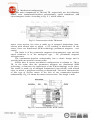
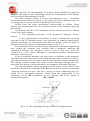
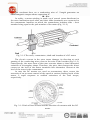
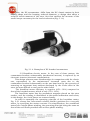
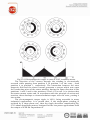
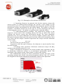
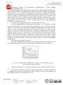
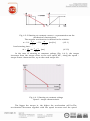
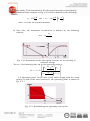
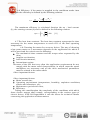
USER MANUAL:
PERMANENT MAGNETS ELECTRIC MOTORS
1. Generalities.
The present manual refers to three types of electric motors designed
and developed in ICPE Department 4:
DC brushed permanent magnets motors hereinafter referred to as TM
and TE, respectively;
AC brushless permanent magnets motors hereinafter referred to as
ACBL;
DC brushless permanent magnets motors hereinafter referred to as
DCBL.
These electric motors are designed for the adjustable speed drives
within the large range and, at the same time, they represent a solution to
complex applications: semiconductor manufacturing process, terrestrial and
aerospace actuating, guiding systems, etc.
The adjustable speed drives represented a field in which the DC
commutator brush electric motors held the supremacy, beacause of the
simplicity with which the rotational speed could be adjusted in a very wide
range and with special dynamic performances-it was practically the only
solution for the high technology applications.
At the same time, the performances imposed to the machine tools,
industrial robots, aerospace applications: efficiency, heavy duty
(inflammability, explosion, advanced vaccum), maintenance increased, the
DC commutator brush electric motors proved to be ever less adequate.
Within this context, it was necessary to remove the commutator-brushes
subassembly and its function was taken over by very complex electronic
architectures, as well as by position and /or speed inductive sliding contactfree tranducers.
After the 1990s, the manufacturing costs of the inductive transducers
and of the movement control electronic architectures decreased considerably
in relation to the manufacturing costs of the DC electromagnetic excitation
or permanent magnets electric motors, fact that finally imposed the
acceptance of these drive systems on the market.
ICPE Department 4 manufactures permanent magnets brushed and
brushless electric motors in a bearing design, at a rated speed of 4000 min-1
and the rated torque of 1.9 Nm. On demand, there can be performed DCBL
with other parameters or in a direct drive design. The transducers used are
from the current production: resolver or tachogenerator. On demand, they
can be delivered with Hall sensors or in the “sensorless” variant.
The productmanufactoring is in accordance with the requirements: SR
EN ISO 9001, SR EN ISO 14001, SR OH SAS 18001.
2. Mechanical configuration.
The main components of TM and TE, respectively are the following:
stator, rotor commutator-brushes subassembly, speed transducer and
electromagnetic brake. According to Fig. 2.1, which shows a
Fig.2.1 Cross section of the TM motor
motor cross section, the rotor is made up of stamped laminations (ironsilicon) with alloted slots to which a DC winding is distributed. In the
stator, there are distributed (SPM technology) permanent magnets - rare
earths.
The brake is of the permanent magnets electromagnetic type and the
speed tranducer is of the analogical type – DC permanent magnets
tachogenerator.
The commutator-brushes subassembly has a classic design and is
provided with two parallel current paths.
ACBLs have a reverse mechanical configuration in relation to TM or
TE, in the sense that the permanent magnets are distributed (SPM
technology, or function the application of the IPM technology) to the rotor.
The stator is made up of stamped laminations (iron-silicon), with alloted
slots, to which a polyphase winding is distributed. The main characteristic
of this type of electric motor is the lack of the commutator-brushes
subassembly. Fig. 2.2 shows the motor cross section. The design is with
Fig.2.2 Cross section of the ACBL motor
bearings, and for the development of a motor heat constant as good as
possible, the stator is free of housing. ACBL can be delivered in the variant
with or without electromagnetic brake.
The rotor position sensor is of the electromagnetic type – brushless
resolver(from the internal output), of the photo-electronic (encoder) type; at
the same time, it can be delivered without position sensor.
DCBLs have the same mechanical construction as ACBLs. These
motors are provided with the rotor position sensor of the magnetic type-the
Hall sensor.
On demand, the DC or AC brushless electric motors can also be offered
in the direct drive design.
3. The operating principle of the permanent magnets electric
motors.
3.1 DC commutator brush motor. In order to explain the operating
principle of the DC brushed motor, one considers its simplest constructive
variant consisting of a rectangular turn with the length l and the width 2r
placed between the poles of a permanent magnet, Fig. 3.1.1.
The considered turn can rotate freely around its rotational longitudinal
axis, within the constant and uniform field of magnetic induction B,
established between the magnetic poles N and S. The turn ends are
connected to a DC source through a commutator-brushes subassembly
forming a closed circuit.
At the considered moment, the turn plane is coplanar to the magnetic
induction direction. Beacause of the fixed position of the brushes P1 and P2,
they will successively be in contact with the two lamellas of the commutator.
The sliding contacts enable the current sense reversing through the turn
when the turn plane is perpendicular to the magnetic induction direction.
The electromagnetic torque generated by the motor is the result of the
interaction between the induction field B and the electric current of intensity
I passing through the turn. The force, acting on each conducting wire of l
length at the considered moment, results from the composition of the
elementary forces dF considered on the elements dl of the length of
theconducting wires:
dF = i dlxB
Fig.3.1.1 The operating principle of the DC brushed motor
The resultant force on a conducting wire of l length generates an
electromagnetic torque whose expression is:
M = Fxr
In reality, a motor winding is made up of several turns distributed to
the rotor lamination stack slots and their ends (terminals) are connected to
the commutator lamellas on which the commutator brushes slide – their
number being equal to the pole number of the motor (Fig. 3.1.2).
Fig. 3.1.2 The rotor, commutator, shaft and brushes of a DC motor
The electric current in the rotor turns changes its direction at each
passing of the conducting wires close to the axis of the brushes (Fig.3.1.3).
Consequently, the wave form of the rotor currents shows a time alternative
variation of rectangular shape. Therefore, the piece that changes the direct
current at the level of the motor terminals into alternative current at the
level of the turns is the commutator.
In case the DC motors are used as servomotors, there occurs the
necessity of an accurate control of the speed at various loading levels of the
motor, a rapid response to sudden variations of the load torque,
respectively.
Fig. 3.1.3 Path of lines of field and the direction of currents with the DC
motor
Thus, the DC servomotors differ from the DC classic motors in their
oblong shape and the housing reduced diameter, a design that offers a
reduced inertia moment of the rotor, fact that enables the increase of the
useful torque necessary for the load acceleration (Fig. 3.1.4)
Fig. 3.1.4. Examples of DC brushed servomotors
3.2 Brushless electric motor. In the case of these motors, the
commutator-brushes subassembly (mechanical inverter) is replaced by an
electronic inverter (electronic commutation).
This design removes some disadvantages in comparison with the classic
one, represented by the maintenance increased costs due to the
commutator-brushes subassembly on the one hand and by the necessity of
removing an important heat amount developed by the Joule effect in the
rotor (an area difficult to cool) on the other hand.
The brushless motor efficiency is superior (85%...90%) compared to
that of the brushed motors, which is only (75%...80%).
The brushless motor has the permanent magnets placed on the rotor
surface, and the winding is distributed to the stator lamination stack slots;
in this design, the Joule losses are removed easily.
In order to exemplify the operating principle of the brushless motor,
Fig. 3.2.1 shows four rotor-stator relative distinct positions for a two-pole
motor, by specifying the stator currents. For simplification, the considered
motor has a single-phase winding, the operating principle being the same as
that of the real motor provided with a three-phase winding.
Fig.3.2.1 Electromagnetic torque in case of a DC brushless motor
The direction of the current through the winding is electronically
reversed while passing from position 2 to position 3 of the rotor , from
position 4 to position 1, respectively. The interaction between the rotor
magnetic field and the stator current generates a torque which acts upon
the conducting wires of the stator winding, having the same direction in the
positions 1 and 3 and in the positions 2 and 4 it is null. It is obvious that
the stator cannot rotate and, in accordance with the principle of action and
reaction, there develops a counterclockwise torque over the rotor, putting it
into action.
The electromagnetic torque ripple is 100%, being unusable in many
industrial applications. It is proved that, if the single-phase winding is
replaced by a three-phase one, then the ripple decreases considerably.Fig.
3.2.2 shows brushless motors, designed for the low power applications from
the output of ICPE SA Department 4.
Fig. 3.2.2 Examples of brushless servomotors
4. Operating features. In general, the electric motors convert the
electric power Pel (characterized through the current I and voltage U) into
mechanical power Pmec (charecterized through the rotational speed n and the
mechanical torque M developed in the motor shaft). The losses in the DC
brushed / brushless motors are of the type PJ (in the windings) and losses
in the magnetic circuit – PFe which, in general, have reduced values.
4.1 Electromechanical constant. The geometrical design of the
magnetic circuit and of the windings shows the way in which the motor
converts the electric energy into mechanical energy. The most important
quantities are: the speed constant (kn) and the torque constant (kM). Thus,
the speed constant represents the speed and the induced electromotive force
(Uind) ratio and the torque constant represents the torque and the absorbed
current ratio:
n = knUind
M = kMI
the functions are strictly linear
In general, with this type of motors, the diameter is much smaller than
the axial length.
4.2 Steady state operation. Maximum continuous torque MC (MN),
maximum permissible speed nmax (nN).
From a mechanical viewpoint, the motor steady state operation can be
at maximum continuous torque or at maximum permissible speed. The
operation of the motors under these limits is stable and reliable .
The inadmissible increase of these parameters causes the wear of the
switching system and, finally, the motor premature failure. Fig. 4.2.1 shows
the diagram of the motor maximum permissible steady state operation.
Fig. 4.2.1
Maximum current IC, environment temperature T0 and winding
maximum temperature T w.
The absorbed current generates Joule losses while passing through the
rotor winding which, function the heat delivery surface and the environment
temperature - T0 [ºC], must be dissipated so that the winding temperature
will not excced the maximum permissible value (insulation class) - T w [ºC] At
the same time, the winding maximum temperature must be correlated to the
mark of brushes. Hence, in the case of “copper-graphite” brushes, due to the
fact that the winding cane bear a high current density, the rotor maximum
temperature can be: 125ºC…155ºC. In the case of the “silver-graphite”
brushes it cannot exced 85ºC.
4.3 Short time regime operation. Winding heat constant - τw.
In some applications, for short periods of time, it is necessary to load
or stress the motor over the values corresponding to the continuous rating.
Thus, in the case of the short time regimes (intermittent), the rated current
value can be exceeded. In general, the time for which the value of the
current IC can be exceeded is about 60 seconds for motors with diameters:
60mm…90mm. Fig. 4.3.1 shows the ratio dependence: the operating current
and the rated current (ION/IN) function the ratio [%] of the operating current
(ON) to the motor rest time. In general, if the motor has a large cooling
surface, the overload standing time increases. The exact calculation of the
overload current depends on the rated current value and the environment
temperature.
4.4 Operating dynamic regimes.
The most important regimes are: the starting and the acceleration up
to an imposed speed. These are performed at constant current/voltage.
ee
Fig. 4.3.1 Ratio of the maximum current to the rated one ION/IN
function the loading degree
Angular acceleration – α, inertia moment (of the rotor and of the load) –
JR,s.
Starting at constant current: the motor generates a constant torque to
a constant acceleration and which a speed linear increase correspond, till
the operating point is reached (Fig.4.3.2).
Fig. 4.3.2 Starting at constant current – representation on the
mechanical characteristic
The angular acceleration is defined in the relation:
kM I
M
α = 104
= 104
[rad/s2]
(4.3.1)
JR JS
JR JS
Load starting time:
J
JS
Δt =
∙Δn∙ R
[ms]
(4.3.2)
kM I
300
In the case of starting at constant voltage (Fig. 4.4.1), the torque
increases from the torque value to the null speed MH , along the speed –
torque linear characteristic, up to the rated torque MN .
Fig. 4.4.1 Starting at constant voltage
Speed – torque characteristic
The bigger the torque is, the higher the acceleration will be.The
acceleration decreases together with the speed increase and the speed
increases slowly. This saturation of the the speed increase is described by
the mechanical time constant in Fig. 4.4.2 and is defined by the following
relation:
JS
J R
J R
τm = 100 R 2 , sau = τ,m = 100 R 2 1
,
JR
kM
kM
were: JS is the load inertia moment.
In this case, the maximum acceleration is defined by the following
relation:
MH
αmax = 104
JR JS
Fig. 4.4.2 Saturation of the time speed increase for the starting at
constant voltage
The no – load starting time up to the operating point is:
1
Δt = = τ,m ∙ln
1
MP MR
MR
MP MR
MR
n0
n0
np
4.5 Operating point. In the case of the motor supply with the rated
voltage UN and at the rated current IN, the operating point is shown in
Fig. 4.5.1
Fig. 4.5.1 Establishing the operating rated point
4.6 Efficiency. If the motor is supplied in the conditions under item
4.5, then the efficiency is defined by the following relation:
η=
nN
30 .000
MN MR
UN IN
The maximum efficiency is calculated function the no – load current
(I0), the starting current (IP) and is defined in the following relation:
ηmax = 1
I0
IP
100
[%]
4.7 The heat time constant. The heat time constant represents the time
necessary for the motor temperature to reach 63% of the final operating
temperature.
4.8 Choosing the motor for accuracy drives. The way of choosing
a low power motor or a servomotor depends on the application for which it
will be used and the criteria are the following:
The mechanical time constant and the torque value requested by the
drive;
Angular acceleration;
Load inertia moment;
Intermittent regime.
Because of the fact that very often the application requirements do not
comply with the motor rated characteristics, in which cases the speed
multipliers are necessary and all the drive mechanical parameters
must be related to the motor shaft.
Other important factors:
Other important factors:
Motor overall size;
Operating environment (temperature, humidity, explosion conditions,
shocks and vibrations, etc);
Maintenance period and costs;
Efficiency.
Taking into consideration the complexity of the conditions with which
these electric motors shall comply, corresponding to the various types of
electric drives, ICPE SA Department 4 ask the users for technical details
concerning the application of these motors.