1
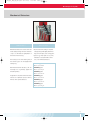
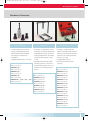
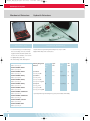
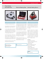
RZ_FAG_Nio_PKW_GB_0809.qxd
08.09.2006
13:54 Uhr
Seite U1
Failure Diagnosis
Guide to troubleshooting wheel bearing
failures and malfunctions
Passenger Cars
RZ_FAG_Nio_PKW_GB_0809.qxd
08.09.2006
13:54 Uhr
Seite 2
Introduction
General remarks
Content
Rolling bearing damage
Diagnosing wheel bearing failures
Causes of failure
Rolling bearings are machine elements
Introduction
2-5
Failure Diagnosis
6-9
Wheel bearings are designed to achieve a
found in a wide range of applications. They
mileage of at least 1,000,000 km without a
work reliably even under the most challen-
problem. However, a rolling bearing can be
ging conditions and premature failure is
damaged by unusual causes which has a
very rare. The first sign of rolling bearing
damage is typically an unusual operating
Mounting Instructions
10 - 15
detrimental effect on its service life.
Mounting Tools by FAG
16-27
• 70% of failures are due to poor lubrica-
The inspection of faulty bearings reveal a
tion: too little or excessive lubrication,
wide and varied range of damages. Exami-
inappropriate lubricant etc.
nation of the bearings alone is generally not
behaviour of the bearing.
• 18% are caused by contamination: intru-
enough to pinpoint the cause of damage,
sion of fluids or solids. This shows the
but rather the inspection of the ambient
importance of an effective sealing, as
parts, the lubrication and sealing as well
a damaged seal will allow lubricant to
as the operating and environmental condi-
leak and contaminants to intrude.
tions. An examination procedure facilitates
• 10% are due to incorrect fitting: bearing
the determination of the failure cause.
forced into position, excessive heat,
wrong adjustment and incorrect play,
Unusual operating behaviour
tapered sleeve overtightened etc.
as signs of damage
General types of rolling
Gradual deterioration of the operating be-
bearing damage
haviour is typically the first sign of bearing
damage. Spontaneous damage caused, for
• Overheating
example, by fitting errors or lack of lubrica-
• Fracture of the outer ring
tion and resulting in immediate failure
• Tipping
rarely occurs. Depending on the operating
• Tight fitting
conditions, a few minutes or, under some
• Fatigue
circumstances, even a few months may
• Rolling body indentations
pass from the time damage begins to the
• Contamination by dirt
moment the bearing actually fails.
• Incorrect lubrication
• Corrosion
• Lip fracture
• Scoring effect damage
• Wrong load direction
2
RZ_FAG_Nio_PKW_GB_0809.qxd
08.09.2006
13:54 Uhr
Seite 3
Introduction
Operating behaviour
Uneven running
Possible cause s
Example s
Damaged ring members or
Increased wheel wobble
rolling bodies
Increased tilting clearance
Vibration in the steering system
Contamination
Intensifying vibrations
Excessive bearing play
Intensifying knocks
Unusual running noise
• Squealing or whistling sound
Insufficient bearing play
• Rumbling or irregular
Excessive bearing play
noise
Damaged rolling contact surface
Contamination
Inappropriate lubricant
• Gradual change in running noise
Temperature-induced change in
bearing play
Damaged raceway
3
RZ_FAG_Nio_PKW_GB_0809.qxd
08.09.2006
13:54 Uhr
Seite 4
Introduction
General remarks
Causes of bearing damages and
Failure diagnosis: Oval deformation
corrective measures
of the wheel bearing
Wheel bearings are among the critical com-
1. Dismount the wheel bearing from the
ponents of a motor vehicle. They make a
locating bore.
major contribution to safe and comfortable
vehicle handling.
2. Check the surface of the wheel bearing
outer ring for two dark spots located op-
Wheel bearings are subject to a wide
posite each other. Examine, whether the
variety of stress factors, such as high wheel
two areas located at 90° of the spots are
speeds, hard knocks resulting from bumpy
not damaged. If this is the case, the loca-
roads, dispersed dirt particles and extreme
ting bore is deformed and the steering
temperatures.
knuckle must be replaced.
These may impair the functioning of the
3. Disassemble the wheel bearing to make
wheel bearing causing the bearing to fail or
sure the ball raceways of the outer ring
seize under unfavourable conditions.
are not polished. First remove the seal
(e.g. using special pliers), then dismount
A seized wheel bearing while driving
the assembly consisting of outer and in-
can lead to dangerous situations and/or
ner ring, cage and balls.
accidents.
4. Clean the raceways of the outer ring and
check for craters corresponding to the
dark spots on the outer ring outside.
These craters confirm the oval deformation of the steering knuckle.
4
RZ_FAG_Nio_PKW_GB_0809.qxd
08.09.2006
13:54 Uhr
Seite 5
Introduction
In general observe the following:
Problem
Cause
The wheel bearing emits loud noises
One of the inner rings is damaged:
(rattling) after being fitted and put into
1. The wheel hub is off centre because it
operation.
Remedy
Replace wheel bearing and hub.
was too tightly fitted.
2. The inner ring was tilted during mount-
Replace complete wheel bearing.
ing on the wheel hub – wrong tool
used – wedge or sleeve between the
pressure plunger and bearing ring
abutment area not parallel.
3. Excessive oval deformation of the locating bore reduces the radial play of the
Replace steering knuckle and
wheel bearing.
wheel bearing in the narrow areas of
the ovally deformed locating bore.
4. Locating bore in steering knuckle
damaged.
Remove minor defects on the wheel hub
(e.g. by polishing) or replace wheel hub
and bearing.
5. Deep scores and indents on both the
Remove minor defects on the wheel hub
wheel hub and wheel bearing caused by
(e.g. by polishing) or replace wheel hub
wrong dismounting technique.
and bearing.
Wheel bearings with little mileage emit
Medium oval deformation of steering
Replace steering knuckle and wheel
noise ( 500-3.000 km).
knuckle locating bore limits the wheel
bearing.
bearing radial play and causes the aforementioned damage.
Excessive heat generation during
starting phase.
1. Too little axial play of the wheel bearing
between wheel hub and steering
Check the settings of the steering knuckle
and wheel hub and re-adjust if required.
knuckle. Incorrect adjustment and/or
mounting of the components.
2. Resulting from incorrect mounting of the
Dismount wheel bearing and make sure
wheel bearing into the locating bore, the
that the snap rings are mounted, replace
snap rings are missing in the locating
wheel bearing if required.
bore causing gradual axial misalignment
of the wheel bearing and the hub. The
rotating hub rubs against the fixed wheel
bearing seat. This generates high friction
causing the temperature to rise in the
wheel bearing environment. The grease
burns and the bearing fails.
5
RZ_FAG_Nio_PKW_GB_0809.qxd
08.09.2006
13:54 Uhr
Seite 6
Failure Diagnosis
Overheating
Fracture of the outer ring
Cause
• Extreme heat from an external source
• Insufficient heat dissipation
• Insufficient cooling or lubrication
Tipping
Cause
• Poor support of the rings in the
bearing housing
• Axial preload due to incorrect bearing
play at high operating temperatures
Cause
• Bent shafts
• Burrs and dirt on the shaft or housing
shoulders
• Shaft threads not located axially parallel
to the bearing seat
• Shaft nuts with end faces not matching
the thread axle
Impact
• Discolouration of rings, rolling bodies
Impact
• Typically, the crack spreads evenly in
and cages with colours ranging from
circumferential direction often in con-
yellow to blue
junction with fractured pieces
• Temperatures exceeding 200 °C
occur a little beyond the middle of the
resistance of the material and can cause
raceway
• In extreme cases the bearing compo-
raceway edges of the standing ring
• With axial loads, these fractions normally
detrimentally affect the hardness and
the bearing to fail
Impact
• Wear marks running angularly to the
• The outer ring external surface displays
an irregular wear pattern
nents will be distorted
• High temperatures can deteriorate or
destroy the lubricant
Remedy
Remedy
• Temperature or overload monitoring
• Improve the mounting of the bearing.
• Sufficient heat dissipation
• Ensure correct bearing play
• Adhere to the fitting instructions of the
manufacturer
Remedy
• Examine shafts and housing for run-outs
at the shoulders and bearing seats
• Machine the thread and bearing seat
using a clamp
• Use precise shaft nuts
6
RZ_FAG_Nio_PKW_GB_0809.qxd
08.09.2006
13:54 Uhr
Seite 7
Failure Diagnosis
Fit too tight
Fatigue
Rolling body indentations
Cause
• Circumferential running marks on
the raceways
Cause
Cause
• Use of wrong bearing (possibly inner
• Static overload of the bearing
design is not matched to the appli-
• Heavy impacts on the bearing
cation – not perceptible from the outside)
• Use of a hammer during mounting
• Bearing or assembled units have been
dropped prior to installation
• The bearing has been fitted onto the
shaft by applying force on the outer ring
Impact
Impact
Impact
• Continuous operation under heavy load,
• The so-called flaking is caused by frac-
poor lubrication and insufficient bearing
tures in the running surface and conti-
by the rolling bodies lead to intensified
play cause premature wear and fatigue
nued abrasion of small particles from the
bearing vibration (noise)
inner and outer ring or the rolling bodies.
• Flaking does not stop, but will, once
• Indentations on the raceways caused
• Advanced indentation can lead to
premature failure of the bearing
started, spread further due to continuous operation.
• Is always accompanied by noticeable
increase of noise emissions
Remedy
• Correct the setting of the bearing play
and/ or of the wheel bearing
Remedy
• Replace the bearing
Remedy
• Use appropriate tool to mount and
dismount the bearing
• Always apply force only to the ring with
fixed seating
7
RZ_FAG_Nio_PKW_GB_0809.qxd
08.09.2006
13:54 Uhr
Seite 8
Failure Diagnosis
Contamination
Incorrect lubrication
Cause
• Unsettled dust, dirt or abrasive
substances from dirty work stations
Corrosion
Cause
• Insufficient lubrication
• Excessive temperatures
• Dirty hands or tools
Cause
• Bearings have been exposed to corrosive
fluids or environments
• Faulty seals or inappropriate lubricant
• Foreign additives in lubricants or
detergents
Impact
• Indentation on rolling bodies and
raceways cause vibrations
Impact
Impact
• Discoloured rolling bodies (blue/brown)
• Red/brownish discolouration or deposits
and rolling body running marks
• Excessive wear of the rolling bodies,
ring members and cages are caused by
overheating and total failure of the
on rolling bodies, raceways and cage
• Increased vibrations followed by
extensive wear
• Increased radial play or loss of preload
lubrication
Remedy
• Clean work stations, tools, objects and
hands reduce contamination risk
• No grinding in the vicinity of the bearing
mounting station
• Keep bearing in the sealed original
packaging until fitting it
• Seal bearing mounting station against
dirty environment
• Cover open, mounted bearings when
interrupting repair work
8
Remedy
• Use correct lubricant in the right amount
• Check preload to reduce bearing
temperature
Remedy
• Avoid use of corrosive fluids in the
bearing’s vicinity
• Use appropriate lubricant with required
specifications
RZ_FAG_Nio_PKW_GB_0809.qxd
08.09.2006
13:54 Uhr
Seite 9
Failure Diagnosis
Lip fractures
Scoring damage
Cause
• Axial load exceeds admissible limits,
lip insufficiently supported
• Axial shock load
• Incorrect mounting/dismounting
Wrong load direction
Cause
• Bearing poorly lubricated and put under
heavy load
Cause
• Angular contact ball bearings are
designed to support loads from just
• Amount or consistence of lubricant
inadequate
one direction
• If load is applied in reverse direction,
• Lack of hydrodynamic lubricant film
between roller face area and lip
• Excessive preload due to thermal
expansion
the elliptic contact area is cut off by the
low shoulder
• This results in very high loads and
temperatures, followed by intensifying
• Off-set position of the rollers caused
vibrations and premature failing
by worn raceway or tilted ring
Impact
• Supporting lips are partially or
completely broken off or fractured
Impact
• Partial or large area welding and deep
scratches in the lips and roller face areas
• Lubricant coking in this area
Remedy
• Keep load within admissible limits
• Observe mounting instructions and
procedures
Remedy
• Use appropriate lubricant with required
specifications
Impact
• The balls show a strapped groove wear
pattern caused by the balls rotating over
the raceway edge
Remedy
• Ensure the correct fitting of the angular
contact ball bearing
• Ensure correct bearing preload
9
RZ_FAG_Nio_PKW_GB_0809.qxd
08.09.2006
13:54 Uhr
Seite 10
Mounting Instructions
Mounting of the Wheel Bearing into the Steering Knuckle
First the complete wheel bearing unit is mounted into the locating bore of the steering knuckle as described below:
1. Mount the wheel bearing into the locating bore of the
1
F
2
steering knuckle ( 4 ) by exerting pressure to the bearing's
outer ring only. Pressure is exerted via a shim ( 1 ) with recess ( 2 )
enabling the pressure force ( F ) to be uniformly transferred to
the outer ring. The steering knuckle rests on the base plate ( 3 )
of the press.
4
3
2. Mount the wheel bearing into the locating bore of the steering
1
F
2
knuckle (5) by applying force to the bearing's outer ring. In order
to do so, the steering knuckle flange side must be located centrally
on the support sleeve ( 3 ) (arrow). The bearing is pressed into the
knuckle in precise alignment by means of a pressure shim ( 1 ) with
5
recess ( 2 ).
4 = press base plate
F = pressure force
3
4
3. Finally, use special pliers to mount a snap ring on the groove in the steering knuckle to secure the wheel bearing in axial
direction.
4. When mounting the wheel bearing into the locating bore the bevel on one side of the bearing is to be observed. This bevel
must be oriented in mounting direction as to avoid tilting of the bearing when pressed into the bore.
Important: Under no circumstances must the pressure force (F) be transferred to the balls in the bearing, as this would cause
indentations in the raceways and damage the bearing!
10
RZ_FAG_Nio_PKW_GB_0809.qxd
08.09.2006
13:54 Uhr
Seite 11
Mounting Instructions
Mounting of the Wheel Hub
1
1. Place the wheel hub ( 4 ) on the base plate (3) of a press.
The in the steering knuckle (5) pre-assembled wheel bearing
F
2
is pressed onto the hub using a mounting sleeve.
5
Important: The sleeve must be positioned only on the face side
of the inner ring!
4
1 = pressure shim
3
F = pressure force
Note: On some vehicles, the parts are mounted in reverse order.
The steering knuckle rests on the base plate while the wheel hub
is pressed in from above.
1
2
1 = wheel hub
2 = steering knuckle
3
3 = mounting sleeve
4 = base plate
4
Important: Do not forget to apply the support sleeve! It supports the inner ring when pressed in and thus prevents grooving of the
ball raceways of the bearing outer ring.
2. Torque down the fixing nut of the wheel bearing with the tightening torque specified by the manufacturer. The correct tightening
torque of the nut is important not only to ensure the wheel is securely fitted, it also ensures that the wheel bearing is running
with optimal play. It is strongly recommended to use a torque wrench to make sure the correct tightening torque is applied.
Note: You must not tilt the wheel bearing during assembly, neither in the locating bore, nor on the wheel hub, as this can
entail severe damage to the wheel bearing. Wheel bearings with factory-fitted seals are already lubricated. They do not require
additional lubrication and must not be cleaned using solvents. Using solvents can cause the bearing to fail prematurely.
11
RZ_FAG_Nio_PKW_GB_0809.qxd
08.09.2006
13:54 Uhr
Seite 12
Mounting Instructions
Installation and Adjustment of Tapered Roller Bearings
in Motor Vehicle Wheel Hubs
Note: Disassembling and mounting tapered roller bearings can be different from one manufacturer to another. In general you
should always adhere to the instructions given by the vehicle manufacturer.
Passenger car mountings with adjusted tapered roller bearings
(non-driven axle).
1. Clean wheel hub body.
2. Slightly oil outer ring seating positions (arrows). Use a plunger ( 2)
to press in both outer rings ( 1 ) and ( 3).
Important: The plunger must be positioned on the outer ring face
1
2
side only! Ensure flush mounting of the outer ring with the housing
shoulders!
3
12
RZ_FAG_Nio_PKW_GB_0809.qxd
08.09.2006
13:54 Uhr
Seite 13
Mounting Instructions
3. Lubricate the inner ring of the inner bearing generously.
Important: Squeeze lubricant also between cage, inner ring
and rollers (arrows)!
4. Mount inner ring into the hub.
5. Mount shaft seal ring into the hub.
Important: Sealing lip must face the bearing!
6. Apply protective cover (1) and intermediate ring (2) on
1
steering knuckle.
Important: The protective cover must fit tightly on the entire
circumference of the steering knuckle application point
(arrows).
2
13
RZ_FAG_Nio_PKW_GB_0809.qxd
08.09.2006
13:54 Uhr
Seite 14
Mounting Instructions
Installation and Adjustment of Tapered Roller Bearings
in Motor Vehicle Wheel Hubs
7. Position wheel hub on steering knuckle.
Important: Make sure not to damage the shaft seal ring!
8. Lubricate the inner ring of the outer bearing generously.
Important: Squeeze lubricant also between cage, inner ring
and rollers (arrows)!
9. Position inner ring of the outer bearing on steering
knuckle.
10. Position shock washer ( 1 ).
11. Bolt on slotted castle nut ( 2).
1
12. Torque down castle nut while rotating the wheel hub,
until a rotating resistance is noticeable.
Important: Use torque wrench and observe the
manufacturer’s repair instructions!
2
14
RZ_FAG_Nio_PKW_GB_0809.qxd
08.09.2006
13:54 Uhr
Seite 15
Mounting Instructions
13. Loosen castle nut for not more than 1/12 of a revolution
until in line with the next split pin hole and secure with
a cotter pin.
14. Check for mounting and tilting clearance.
Note: The wheel bearing must rotate easily without
seizing.
No tilting clearance must be noticeable on the rim.
If required, replace shock washer or nut.
If available, use measuring device to check the axial
play of the bearing.
15. Remount the cover.
16. Perform a test run to check whether the mounting play
has changed. Re-adjust the bearing if required.
15
RZ_FAG_Nio_PKW_GB_0809.qxd
08.09.2006
13:54 Uhr
Seite 16
Mounting Tools by FAG
Socket Wrench for Mounting
and Disassembling
Mounting Tool Kit
FAG
FAG
Mo u n t i n g To o l K i t
Socket Wrenche s
The FAG mounting tool kit allows for a cost-
Contents of:
For locknuts KM0 to KM20. The socket wren-
effective and safe mounting of rolling bea-
FITTING.TOOL.ALU.SET10-50
ches FAG LOCKNUT.SOCKET… allow for a
rings with bore diameters of up to 50 mm.
33 mounting rings
simple tightening and loosening of locknut
It can also be used to fit sleeves, interme-
for bore diameters of 10-50 mm
on shafts, adapter and extraction sleeves.
diate rings, seals and similar parts.
and outer diameters of up to 110 mm
3 mounting sleeves
They require less space on the locknut cir-
Use a suitable mounting sleeve and hit with
Nonrecoil hammer, 1 kg
cumference than hook wrenches and ena-
a hammer to drive tightly fitting inner rings
Suitcase dimensions: 440~350~95 mm
ble ratchets and torque wrenches to be
onto the shaft or outer rings into the hou-
Overall weight of the set: 4.5 kg
used. For increased work safety, socket
sing bore. Using a mounting sleeve helps to
Components also available as individual
wrenches should be secured using a
prevent mounting forces being transferred
parts.
locking pin or rubber washer. FAG socket
via the rolling bodies and raceways which
wrenches therefore have a bore to apply
could damage the parts severely.
the locking pin and a groove to attach
the rubber washer. Locking pin and rubber
The FITTING.TOOL.ALU.SET10-50 comprises
washer are included with the socket
mounting sleeves made from aluminium
wrench.
and mounting rings made from plastic. The
16
tools are easy to handle and available at
Ordering example for an FAG socket wrench
low cost.
suitable for locknut KM5:
FITTING.TOOL.ALU.SET10-50
LOCKNUT.SOCKET.KM5
Part no. 400 6001 10
Part no. 400 6063 10
RZ_FAG_Nio_PKW_GB_0809.qxd
08.09.2006
13:54 Uhr
Seite 17
Mounting Tools by FAG
Hook and Pin Wrenches for Mounting and Disassembling
FAG Flexible
FAG Flexible
FAG Flexible
Head Hook Wrench
Head Pin Wrench
Head Face Pin Wrench
For locknuts KM0 to KM40 and precision
For precision locknuts AM15 to AM90.
For precision locknuts LNP017 to LNP170.
The FAG flexible head hook wrenches of the
The FAG flexible head pin wrenches of the
The FAG flexible head face pin wrenches of
LOCKNUT.FLEXI-HOOK… series allow for the
LOCKNUT.FLEXI-PIN… series allow for the
the LOCKNUT.FACE-PIN… series allow for
tightening and loosening of locknuts (preci-
tightening and loosening of precision nuts
the tightening and loosening of precision
sion nuts) on shafts and adapter and extrac-
on shafts if no torque is specified. Using FAG
nuts on shafts if no torque is specified.
tor sleeves if no torque is specified. The
flexible head pin wrenches allows for the
Using FAG flexible head face pin wrenches
flexible head hook wrench of the series
mounting of small bearings onto tapered
allows for the mounting of small bearings
LOCKNUT.FLEXI-HOOK allows for the mount-
shaft seats. The bearings are tightened via
onto tapered shaft seats. The bearings are
ing and dismounting of locknuts with diffe-
radially arranged holes.
tightened via axially arranged holes.
Ordering example for an FAG flexible head
Ordering example for an FAG flexible head
Ordering example for an FAG flexible head
hook wrench suitable for locknuts KM14 to
pin wrench suitable for locknuts AM35 to
face pin wrench suitable for locknuts
KM24:
AM60:
LNP017 to LPN025:
nuts ZM06 to ZM150 and ZMA15/33 to
ZMA 100/140.
rent diameters.
LOCKNUT.FLEXI-HOOK.KM14-24
LOCKNUT.FLEXI-PIN.AM35-60
LOCKNUT.FACE-PIN.LNP17-25
Part no. 400 6089 10
Part no. 400 6094 10
Part no. 400 6079 10
17
RZ_FAG_Nio_PKW_GB_0809.qxd
08.09.2006
13:54 Uhr
Seite 18
Mounting Tools by FAG
Hook and Pin Wrenches for Mounting and Disassembling
FAG Double
FAG Double
Individual Double
Hook Wrench Kit
Hook Wrench Sets
Hook Wrenche s
This service kit includes a service-case con-
(former FAG designation 173556 and
(former FAG designation DHN5 to DHN13).
taining a double hook wrench, a torque
173557). The sets include four or five
Double-hook wrenches are also available
wrench and a user manual. The torque
double-hook wrenches. The remaining
individually. Each double hook wrench is
wrench allows for the precise definition of
items in the case are identical to the kit.
engraved with the torsion angles for the
the initial mounting position at a defined
self-aligning ball bearings to be mounted
tightening torque.
using this particular wrench, so that the
sliding distance and reduction in radial
clearance can be precisely set.
18
LOCKNUT.DOUBLEHOOK.KM5.KIT
LOCKNUT.DOUBLEHOOK.KM5-8.SET
LOCKNUT.DOUBLEHOOK.KM13
Part no. 400 6107 10
Part no. 400 6096 10
Part no. 400 6115 10
LOCKNUT.DOUBLEHOOK.KM13.KIT
LOCKNUT.DOUBLEHOOK.KM9-13.SET
Part no. 400 6106 10
Part no. 400 6097 10
RZ_FAG_Nio_PKW_GB_0809.qxd
08.09.2006
13:54 Uhr
Seite 19
Mounting Tools by FAG
Mechanical Extractors
Me chanical
Two-Arm
Extractors
Extractors
Mechanical extractors are used to dismount
small rolling bearings with bore diameters
of up to 100 mm that are tightly fitted on
the shaft or in the housing.
• Allow for the dismounting of complete
rolling bearings with tightly fitted inner
rings and other parts, such as ring gears.
• Span: 80-350 mm, depth: 100-250 mm;
available in a set (stand with 6 extrac-
The bearing can be dismounted gently if
tors) or as individual extractors.
the extractor grips onto the tightly fitted
bearing ring.
ABZIEHER54.SET
Part no. 400 6118 10
With mechanical FAG extractors, the dis-
ABZIEHER54.100
mounting force is generally applied via
Part no. 400 6119 10
threaded spindles.
ABZIEHER54.200
Part no. 400 6120 10
Alongside two-arm, three-arm and four-arm
ABZIEHER54.300
devices and a hydraulic pressure device,
Part no. 400 6121 10
FAG also offers special extractors.
ABZIEHER54.400
Part no. 400 6122 10
ABZIEHER54.500
Part no. 400 6123 10
19
RZ_FAG_Nio_PKW_GB_0809.qxd
08.09.2006
13:54 Uhr
Seite 20
Mounting Tools by FAG
Mechanical Extractors
Three-Arm
Hydraulic
Extractors
Extractors
P re s s u re To o l s
for Ball Bearings
• For the dismounting of complete rolling
bearings or tightly fitting inner rings
extractors to loosen tightly fitting parts
• Span: 85-640 mm, depth 65-300 mm
• The tool considerably facilitates bearing
• For dismounting complete radial ball
bearings
• For tightly fitting outer ring
extraction as it provides axial forces
• For bearing without radial access
of 80 or 150 kN; the larger tool has a
• Three kits with different sets of claws
hydraulic return mechanism
available
ABZIEHER52.085
ABZIEHER44.080
ABZIEHER56.020.SET
Part no. 400 6126 10
Part no. 400 6130 10
Part no. 400 6132 10
ABZIEHER52.130
ABZIEHER44.150
ABZIEHER56.120.SET
Part no. 400 6127 10
Part no. 400 6131 10
Part no. 400 6133 10
ABZIEHER52.230
ABZIEHER56.220.SET
Part no. 400 6128 10
Part no. 400 6134 10
ABZIEHER52.295
Part no. 400 6129 10
20
• Used together with mechanical
RZ_FAG_Nio_PKW_GB_0809.qxd
08.09.2006
13:54 Uhr
Seite 21
Mounting Tools by FAG
Mechanical Extractors
Spe cial Extractors
Extracting
Internal
for Bearings
Device s
Extractor Set
• For radial bearings (deep groove ball
• For all types of rolling bearings. For the
• For deep groove ball bearings and
bearings, self-aligning ball bearings,
dismounting of complete rolling bearings
angular contact ball bearings. The inter-
cylindrical, tapered and self-aligning
or tightly fitting inner rings. The extract-
nal extractor set includes nine extractors
roller bearings); indicate bearing
ing and separating devices are available
and can be used on bearing holes with
manufacturer
in 5 different sizes with spans of up to
diameters of 5-70 mm.
• For tightly fitting inner and/or outer ring
210 mm.
• Especially suitable when the bearing
• For tightly fitting outer ring
• The inner ring hole must be freely
ABZIEHER64.400
inner ring is adjacent to a shoulder on
Part no. 400 6135 10
the shaft without extraction slots. Good
ABZIEHER64.500
radial access to the bearing location is
ABZIEHER62.SET
Part no. 400 6136 10
required.
Part no. 400 6140 10
ABZIEHER64.600
accessible.
ABZIEHER62.100.005
Part no. 400 6137 10
ABZIEHER49.100.060
Part no. 400 6141 10
ABZIEHER64.700
Part no. 400 6150 10
ABZIEHER62.100.007
Part no. 400 6138 10
ABZIEHER49.100.075
Part no. 400 6142 10
ABZIEHER64A..., ~64B…, ~64C…, ~64D
Part no. 400 6151 10
ABZIEHER62.100.010
Part no. 400 6139 10
ABZIEHER49.200.115
Part no. 400 6143 10
Part no. 400 6152 10
ABZIEHER62.100.014
ABZIEHER49.300.150
Part no. 400 6144 10
Part no. 400 6153 10
ABZIEHER62.100.020
ABZIEHER49.400.210
Part no. 400 6145 10
Part no. 400 6154 10
ABZIEHER62.100.030
Part no. 400 6146 10
ABZIEHER62.200.040
Part no. 400 6147 10
ABZIEHER62.200.050
Part no. 400 6148 10
ABZIEHER62.200.060
Part no. 400 6149 10
21
RZ_FAG_Nio_PKW_GB_0809.qxd
08.09.2006
13:54 Uhr
Seite 22
Mounting Tools by FAG
Mechanical Extractors
Hydraulic Extractors
Internal
Hydraulic Standard Extractor with
Extractor Set
Integrated Hand Pump
• For standard deep groove ball bearings.
The set consisting of six sets of extract-
Compact extractors generating dismounting forces of up to 80kN.
Supplied with safety net in a sturdy case.
ing jaws and two threaded spindles can
be used on bore diameters of 10-100 mm.
• For tightly fitting outer ring
• No dismounting of the shaft required
PULLER.INTERNAL.SET10-100
Ordering designation Extracting
Span
Depth
Lift
Weight
Part no. 400 6155 10
Extractor
mm
mm
mm
kg
40
150
152
55
4,5
60
200
152 (190*)
82
4,9
80
250
190 (229*)
82
6,6
force
kN
PULLER.INTERNAL.ARM-A1
Part no. 400 6156 10
PULLER.INTERNAL.ARM-A2
400 6166 10
Part no. 400 6157 10
400 6167 10 JAW
PULLER.INTERNAL.ARM-A3
400 6168 10
Part no. 400 6158 10
400 6169 10 XL
PULLER.INTERNAL.ARM-A4
400 6170 10 JAW
Part no. 400 6159 10
400 6171 10 Long JAW
PULLER.INTERNAL.ARM-A5
400 6172 10
Part no. 400 6160 10
400 6173 10 XL
PULLER.INTERNAL.ARM-A6
400 6174 10 JAW
Part no. 400 6161 10
400 6175 10 Long JAW
PULLER.INTERNAL.SPINDEL.M12
Part no. 400 6162 10
PULLER.INTERNAL.SPINDEL.M16
Part no. 400 6163 10
PULLER.INTERNAL.SUITCASE
Part no. 400 6164 10
PULLER.INTERNAL.INLAY
Part no. 400 6165 10
22
* optionally with longer extracting arms; spare parts available individually
RZ_FAG_Nio_PKW_GB_0809.qxd
08.09.2006
13:54 Uhr
Seite 23
Mounting Tools by FAG
Three-Section
Extraction Plate
Electrical Heating Plate
Induction Heating Device
FAG Three-Se ction
FAG Ele ctric
FAG Induction
Extraction Plate
Heating Plate
Heating Device
Cylindrical bearing seats meant to fit tightly
Many rolling bearings and other rotationally
on the shaft must be heated prior to moun-
symmetric steel parts are tightly fitted on
They facilitate the dismounting of bearings,
ting. Sufficient thermal expansion is achie-
the shaft. Especially larger parts can be
tightly fitting inner rings and other parts.
ved at 80 to 100 °C. Temperature must not
fitted much easier if they are heated prior
under no circumstances exceed 120 °C to
to mounting.
For hydraulic and mechanical extractors.
Its load carrying capacity and extraction
make sure that the material structure and
force generation are precisely synchronised.
hardness characteristics do not change.
The SPIDER extraction hooks are attached
The quick and clean process of induction
heating is superior to the traditional
right behind the extractor tie bolts and allow
The FAG heating plate HEATER.PLATE with
methods and is therefore particularly well
for evenly applied extraction forces.
controlled temperature can be used to heat
suited for the use in volume mounting.
rolling bearings. Cover the bearing with a
Induction heating can be used on complete
This prevents deformation or tilting of even
metal sheet and turn it regularly to ensure
bearings, rings of cylindrical roller bearings
the most tightly fitting parts. The high
the bearing is uniformly heated.
or needle bearings, and rotationally
extraction forces are solely applied to e.g.
symmetric steel parts, such as labyrinth
the bearing inner ring. Normally, bearing
Alongside rolling bearings (max. 120 °C),
and shaft remain intact and can be re-used.
the heating plates are also suitable to heat
labyrinth, shrink and seal rings.
rings, roll couplings, wraps etc.
Advantages
The field-proven extractors can be mounted
• Fast, energy-saving working
with little effort behind the bearing.
• Suitable for rolling bearings and other
ring-shaped steel parts
PULLER.TRISECTION50
HEATER.PLATE
• Advanced safety
Part no. 400 6176 10
Part no. 400 6179 10
• Environmentally friendly, oil-free
PULLER.TRISECTION100
• Uniform, controlled heating
Part no. 400 6177 10
• Simple handling
• Automatic demagnetisation
• Improved efficiency, as the best suitable
size can be selected for every application
HEATER10
Part no. 400 6178 10
23
RZ_FAG_Nio_PKW_GB_0809.qxd
08.09.2006
13:55 Uhr
Seite 24
Mounting Tools by FAG
Gloves
Feeler Gauges
FAG Heat-Insulated
Heat and Oil
FAG
Glove s
Re sistant Glove s
Feeler Gauge s
The FAG heat-insulated gloves are particu-
The FAG heat and oil resistant gloves are
Feeler gauges are used to measure the
larly well suited for the handling of rolling
particularly well suited for the handling of
radial bearing clearance, especially when
bearings or other parts heated prior to
rolling bearings or other parts heated and
mounted on tapered shaft seats and adap-
mounting or dismounting.
lubricated prior to mounting or dismounting.
ter and extracting sleeves.
The outside material is hard-wearing poly-
Their outstanding properties derive from
FEELER.GAUGE100
ester, heat resistant to temperatures up to
a multiple-layer structure made of different
Part no. 400 6182 10
150°C.
fibres.
FEELER.GAUGE300
Part no. 400 6183 10
The inside material is non-irritant cotton.
Special characteristics:
• Resistant to temperatures up to 250°C
Special characteristics:
• Not flammable
• Resistant to temperatures up to 150°C
• Heat resistant even when wet
• Lint-free
• Admitted for protection against
• Non-asbestos
mechanical (DIN EN 388) and thermal
• Comfortable
(DIN EN 407) influences
• Cut-resistant
• Cotton-free
• Cut-resistant
24
HANDSCHUH1
HANDSCHUH2
Part no. 400 6180 10
Part no. 400 6181 10
RZ_FAG_Nio_PKW_GB_0809.qxd
08.09.2006
13:55 Uhr
Seite 25
Mounting Tools by FAG
Mounting Paste
Anti-Corrosion Oil
FAG
FAG
Mounting Paste
Anti-Corrosion Oil
This mounting and multiple-purpose paste
The anti-corrosion oil is particularly well
has proven especially valuable for the
suited for unpacked rolling bearings. But it
mounting of rolling bearings. It facilitates
can also be applied to bare metal surfaces
the mounting of bearing rings and prevents
of equipment, machines and machine com-
stick-slip, scoring marks, wear and fretting
ponents stored indoors to provide long-
corrosion. In addition, the mounting paste
term protection against corrosion.
protects the bearing against corrosion.
Normally, it is not necessary to wash antiIt is pale in colour and does not soil. The
corrosion oil out of rolling bearings, as the
mounting paste is applied in a thin layer so
oil behaves neutrally towards all conventio-
that the metallic lustre turns slightly dull.
nal rolling bearing greases and oils. It can
The admissible operating temperature
easily and reliably be removed using alka-
ranges between -30°C and +150°C. The
line solvents or neutral cleaning agents.
paste is resistant to water, steam and a
variety of alkaline and acid agents.
Product range:
Product range:
70g tube
0.4 l spray can with ozone-safe propellant
250g tube
CO2.
400g cartridge
1 kg can
ARCA.MOUNTINGPASTE.70G
ARCA.ANTICORROSIONOIL.400G*12
Part no. 400 6194 10
Part no. 400 6193 10
ARCA.MOUNTINGPASTE.250G*10
Part no. 400 6195 10
25
RZ_FAG_Nio_PKW_GB_0809.qxd
08.09.2006
13:55 Uhr
Seite 26
Mounting Tools by FAG
Rolling Bearing Greases
1.5 kg and 10 kg Containers
Grease Gun
Arcanol
FAG Grease Gun
MULTITOP
with Armoured Hose
DIN 51825
KPSN-40
Under challenging operating conditions
Thickener
Lithium soap with EP additives
or in harsh environments, rolling bearings
Base oil
Mineral oil + ester
often require re-lubrication via grease
Base oil viscosity at 40°C
85 [mm2/s]
nipples. This work can be performed easily,
Consistence (NLGI class)
2
cleanly and quickly using the FAG grease
Operating temperature (°C)
- 40 to +150
gun with attached armoured hose. All parts
Max. long-term operation temperature (°C) 80
comply with DIN 1283.
Typical fields of application
Universal grease for ball and roller bearings
Grease Gun
used in rolling mills, construction machines,
Reservoir diameter: 56 mm, overall length
motor vehicles, splining and grinding
of the gun: 390mm, delivery capacity:
spindles which are subject to increased
2 cm 3/stroke, pressure: max. 800 bar.
speeds, high loads, high and low
The gun is filled with either bulk grease or a
temperatures
cartridge according to DIN 1284.
Extremely suitable
• Reservoir capacity for bulk grease: 500 cm 3
High temperatures
Suitable
• 400g cartridge as per DIN 1284 (diame-
Low friction
Very suitable
ter 53.5 mm, length 235mm), connection
High speeds
Very suitable
thread: GB/i, weight: approx. 1.5 kg
High loads
Very suitable
Low speeds
Very suitable
Vibration
Very suitable
Support for seals
Suitable
Armoured Hose
Re-lubrication
Extremely suitable
Length: 300 mm, connection thread: GB/i,
Low temperatures
ARCA.GREASE-GUN
Part no. 400 6191 10
equipped with hydraulic grip coupling for
tapered lubrication nipples according to
Part no.
DIN 71412. Instead of the hydraulic grip
400 6188 10
coupling, sliding couplings for button head
ARCA.GREASE.MULTITOP.1KG
1 kg
ARCA.GREASE.MULTITOP.5KG
5 kg
400 6189 10
lubricating nipples according to DIN 3404 or
ARCA.GREASE.MULTITOP.10KG
10 kg
400 6190 10
other nozzles can be used. These connectors are available in specialist retail stores.
ARCA.GREASE-GUN.HOSE
Part no. 400 6192 10
26
RZ_FAG_Nio_PKW_GB_0809.qxd
08.09.2006
13:55 Uhr
Seite 27
Mounting Tools by FAG
Temperature
Measuring Devices
Digital Hand
Tachometer
Sonar Device
FAG Infrared Thermo-
FAG Digital
FAG
meter TempChe ck PLUS
Hand Tachometer
Sonar Device
The FAG infrared thermometer TempCheck
The tachometer provides for two operation
The sonar device allows for the quick, easy
PLUS measures the infrared radiation emit-
modes:
and reliable control of rolling bearing noise.
ted by an object and uses this to calculate
• Direct speed measurement with adapter,
Changes in noise caused by wear, pitting
the surface temperature. The contactfree process allows for the temperature
measurement of objects which are difficult
track wheel and measuring tips
• Contact-free optical measurement using
a reflecting mark
formation or distortion of the bearing
can thus be detected at an early stage if
inspection is carried out regularly. This
Direct speed measurement
helps to avoid unexpected interruptions
Plug on the adapter supplied with the mea-
in operation and more serious machine
The device is very light (it only weighs 150 g)
suring device. Through contact with the
damage. The device works like a doctor’s
and can therefore be taken practically
component, the rubber tip measures the
stethoscope.
anywhere it is needed. The FAG infrared
rotational speed or the tracking wheel the
thermometer TempCheck PLUS covers a
surface speed.
to reach or that are moving.
measuring range of -32°C to +530°C. It
The tips of the earpiece are placed in the ear
channels to provide insulation against back-
can be used for thermal monitoring of
TACHOMETER
ground noise. The insulating grip is held
machine components.
Part no. 400 6184 10 contains:
like a pencil between thumb and index
Summary of the advantages of the
finger and the sensing tip is placed firmly on
TempCheck PLUS:
Digital hand tachometer, adapter for direct
the part to be measured. If a noise is heard,
• Quick and precise temperature
1:1 measurement, tracking wheel 1/10 mm,
the sensor is moved until the noise reaches
tracking wheel 6in, rubber tip, 10 reflecting
its maximum volume.
measurement
• State-of-the-art infrared measurement
marks, user manual, carrying case
Contact-free speed measurement
SOUND.CHECK
• Easy to handle
Apply a reflecting mark on the machine
Part no. 400 6187 10
• Reduction of unplanned down-time periods
component to be measured. This mark
• Low purchase cost
is detected by photoelectric means using
technology
visible red light. The device displays the
TEMP.CHECK.PLUS
revolutions per minute.
Part no. 400 6186 10
TACHOMETER.REFLEX.MARKS
Contains: measuring device with battery,
Part no. 400 6185 10
strap, user manual and carrying case
Contains: 10 reflecting marks
27
08.09.2006
13:54 Uhr
Seite U4
955 1000 430 1637/5.0/9.2006/OD-GB
RZ_FAG_Nio_PKW_GB_0809.qxd
Phone: +49 (0) 1801-753-333*
Fax: +49 (0) 6103-753-297
[email protected]
www.LuK-AS.com
*4,6 ct/Min aus dem deutschen Festnetz