1
FCINT Smart Building Controller
User Manual
Contents
Purpose ................................................................................................................. 3
Main use cases and overall architecture ......................................................................... 4
Basic installation and setup ........................................................................................ 8
Event Handling in the Smart Building Controller .............................................................. 12
The SBC Service endpoint .......................................................................................... 14
SBC Service Interface ............................................................................................ 14
The SBC Service Calling Convention ........................................................................... 21
Schedule specification and execution ........................................................................... 23
Policy specification and execution ............................................................................... 27
Policy scheduling .................................................................................................... 30
Alarm scheduling .................................................................................................... 39
Purpose
This document describes the functionality and interfaces of the FCINT Smart
Building Controller (SBC) to other FCINT system components. This guide includes
step-by-step tutorials on how to set up, configure and use the Smart Building
Controller in the following scenarios:
-
Basic installation and setup
-
Event type registration and the event subsystem
-
SBC Service interface
-
Schedule specification and execution
-
Policy specification and enforcement
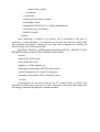
Main use cases and overall architecture
The FCINT Smart Building Controller (SBC) is the orchestration component of the
FCINT project. The overall deployment diagram of the FCINT system is outline in
figure 1.
Figure 1. Overall FCINT architecture
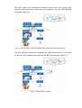
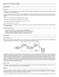
The main use case of the FCINT project can be summarized as follows (figures
2..7):
-
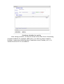
A user downloads the Smart Building Controller from the FCINT portal and
installs it inside his/her smart home or building (Figure 2);
Figure 2. Download and install the FCINT client software
-
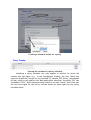
The user discovers on the FCINT portal the services for the devices it owns
and install them (figure 3);
Figure 3. Discover and install services
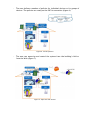
-
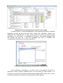
The user make the connections between devices and the related web
services, then devices are discovered and installed into the Smart Building
Controller (figure 4);
Figure 4. Device discovery and installation in the FCINT Smart Building Controller
-
The user defines a number of schedules for individual devices or for groups
of devices. The schedules are ready on the SBC for execution (figure 5)
Figure 5. Create device schedules
-
The user defines a number of policies for individual devices or for groups of
devices. The policies are ready on the SBC for execution (figure 6)
Figure 6. Create policies
-
The user can supervise and control the system from the building’s LAN or
from the Web (figure 7)
Figure 7. Supervise and control
Basic installation and setup
The
SBC
installation
package
http://www.fcint.ro/portal/Download.aspx
is
available
online
at:
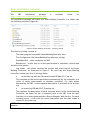
The installation package will install the Smart Building Controller in a folder with
the following structure (figure 8):
Figure 8. Smart Building Controller - directory listing
The directory listing consists of:
-
The main program executable (SmartBuildingController.exe)
-
The Configuration file (SmartBuildingController.exe.config)
-
EventBase.DLL – a DLL needed by the SBC
Readme.txt – a brief how to on the specification of schedules, policies and
the use of the system.
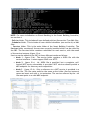
logs folder – this folder contains the activity and event logs of the Smart
Building Controller, as illustrated in figure 9. For each day the Smart Building
Controller creates two files in the logs folder:
o
An activity log with the file name format DD.MM.YYYY_log.txt
This contains all the actions performed automatically by the controller as a
result of policy enforcement or schedule execution. For each action
executed by the SBC, a time stamped description is provided in the activity
log.
o
An event log: DD.MM.YYYY_Eventlog.txt
This contains the description of each incoming event to the Smart Building
Controller. An event can be: a command sent to the SBC from the User
Interface or an event generated by a Device Wrapper Web Service. For each
incoming event, a line with the event description and the time stamp is
created in the event log.
NOTE: After midnight, new event log files are automatically created by the SBC on
demand.
Figure 9. Activity and event logs
-
EventTypes folder (figures 8 and 10). This folder includes the complete list of
device-dependent event types that can be intercepted by the Smart Building
Controller. Event types are packaged together in .NET event type assemblies.
Each event type stored in the event type assemblies must be a public and XML
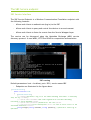
serializable class. At initialization, the Smart Building Controller automatically
registers all even types defined in the EventTypes folder (figure 11).
Figure 10. Event types registered in the Smart Building Controller
Figure 11. Smart Building Controller initialization
NOTE: For more information on Event Handling in the Smart Building Controller,
see section 4.
- Policies folder. This includes all user-defined policies (See section 7) as XML files.
- Schedules folder. This includes all user-defined schedules (see section 6) as XML
files.
- Services folder. This is the main folder of the Smart Building Controller. The
Services folder contains all the services currently installed which can be called by
the SBC. The Services folder contains a subfolder for each service, with the name
of the service instance (figure 12.a) .
Services can be added to the SBC in three different modes as follows:
• Mode 1 - figure 12.b) – The service folder contains a .WSDL file with the
service interface. It must support SOAP over HTTP
• Mode 2 – figure 12.c) – No .WSDL file is specified, but a complete, selfhosted WCF service executable is provided. WCF services should provide a
MEX endpoint for discovery and composition
• Mode 3 – figure 12.d) – Only a reference to a WCF service is provided in a
text file. The file name must be the same as the folder (Service instance)
name and must end with a .txt extension. The service referred by the .txt
file must point to a valid MEX endpoint.
Figure 11 – The structure of the Services folder in the Smart Building Controller
11.a – One subfolder for each installed service instance, bearing the name of the service instance
11.b – A lights service specified only by its .WSDL file;
11.c – A Voice recognition service fully specified by a WCF (MEX) binary, no WSDL file specified
11.d – A reference to an external WCF service (VirtualSmokeDetector) specified only by the
service’s WCF MEX URL.
Event Handling in the Smart Building Controller
Event handling is performed by using the following mechanism:
- the Smart Building Controller listens on the TCP port 2000 for incoming
events
- events are sent by services to the SBC in XML serialized form
- the SBC executes user defined policies for each type of event specified in
the policy files
- Events are broadcasted to all listening SBC clients (UI programs) in XML
serialized form
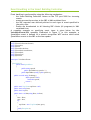
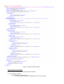
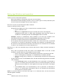
A complete example on specifying event types is given below for the
VoiceRecoEvents.DLL assembly illustrated in figure 9. In this example, a
SpeechReco event is defined for a speech recognition WCF service which sends
SpeechReco events to the SBC as the user speaks.
using System;
using System.Collections.Generic;
using System.Net;
using System;
using System.Net.Sockets;
using System.Xml.Serialization;
using System.Xml;
using System.Text;
using System.IO;
namespace VoiceRecoEvents
{
[Serializable]
public class SpeechReco
{
public string speech;
public SpeechReco(){speech="";}
public SpeechReco(string s){this.speech=s;}
public override string ToString() {
if(this.speech!=null)
return this.speech;
return "";
}
public static TcpClient tcpClient = null;
public static string host;
public static int port;
public static void Init(string Host, int Port)
{
host = Host;
port = Port;
try
{
tcpClient = new TcpClient(host, port);
}
catch (Exception e)
{
Console.WriteLine(e.Message);
}
}
public void Send()
{
//here I put the XML serializer and write the code to send it to the TCP Server
try
{
XmlSerializer eventSerializer = new XmlSerializer(this.GetType());
StringWriter wr = new StringWriter();
XmlTextWriter xmlWriter = new XmlTextWriter(wr);
eventSerializer.Serialize(wr, this);
if (tcpClient == null)
return;
NetworkStream io = tcpClient.GetStream();
byte[] bytesArray = Encoding.ASCII.GetBytes(wr.ToString());
io.Write(bytesArray, 0, bytesArray.Length);
}
catch (Exception e)
{
Console.WriteLine(e.Message);
try
{
tcpClient = new TcpClient(host, port); //try re-sending
XmlSerializer eventSerializer = new XmlSerializer(this.GetType());
StringWriter wr = new StringWriter();
XmlTextWriter xmlWriter = new XmlTextWriter(wr);
eventSerializer.Serialize(wr, this);
if (tcpClient == null)
return;
NetworkStream io = tcpClient.GetStream();
byte[] bytesArray = Encoding.ASCII.GetBytes(wr.ToString());
io.Write(bytesArray, 0, bytesArray.Length);
}
catch (Exception exc) { Console.WriteLine(exc.Message);}}}}}
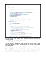
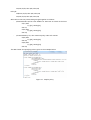
As it can be seen in the example above, each event type must implement the
following methods:
• public static void Init(String Host, int Port)
• public void Send()
The Init method is automatically called by the SBC for each class in each
EventTypes assembly with the IP address of the SBC and with the event listening
port (default 2000).
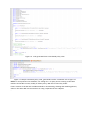
Each Event type class must connect to the SBC in the Init method and implement a
public void Send() method, which serializes the event object and sends it to the
SBC using the TCP connection established in the Init() method. In case of delivery
failure, a SBC reconnect + resend attempt must be done (this situation is
illustrated in the Send() method in the example above in the catch() branch).
The SBC Service endpoint
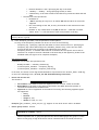
SBC Service Interface
The SBC Service Endpoint is a Windows Communication Foundation endpoint with
the following features:
-
Allows web clients to authenticate (log in) to the SBC
-
Allows web clients to query and control the devices in an environment
-
Allows web clients to listen for events from the Service Wrapper Layer
The service can be discovered using the Metadata Exchange (MEX) service
discovery protocol. It uses WSDL, HTTP and SOAP for composition and execution.
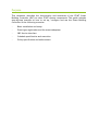
SBC running
Default parameters: host = localhost, port= 5021, service name=SBC
-
Endpoints are illustrated in the figure above
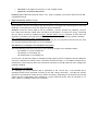
[ServiceContract]
public interface ISBC
{
[OperationContract]
/// <summary>Performs a log in to the Smart Building Controller. A necessary
step for any </summary>
/// <param name="userName">User name registered in the Smart Building
Controller's local database</param>
/// <param name="password">password for the user</param>
/// <returns><error>Error description</error> in case an error occurs or the
sessionID otherwise</returns>
string DoLogin(string userName, string password); //performs a local log in
operation
[OperationContract]
/// <summary>Listens for asynchronous events given a maximul polling
delay.</summary>
/// <param name="sessionID">A valid session ID </param>
/// <param name="environmentName">the environment being monitored</param>
/// <param name="deviceOrServiceName">the name of a device or service
executing inside the SBC. Can be "all" for any device or service</param>
/// <param name="pollingDelay">a maximum wait delay for events, expressed in
seconds</param>
/// <returns><error>Error description</error> in case an error occurs, or an
<events count="N"> tag with N child elements of various types; each one is the XML
serialization of an event</returns>
string ListenForEvents(string sessionID, string environmentName,string
deviceOrServiceName,int pollingDelay,double lookbackMinutes); //listens for events
[OperationContract]
/// <summary>Sends a command to one or more devices in the environment by
issuing a low level call to the underlying control web service</summary>
/// <param name="sessionID">A valid session ID identifying the caller</param>
/// <param name="environmentName">the environment being monitored</param>
/// <param name="deviceID">the name of the device or of the service</param>
/// <param name="command">the command to be sent to the service or to the
device</param>
/// <returns><error>Error description</error> or the result of the call to the
device or to the service itself, as a string</param>
string ControlDevice(string sessionID, string environmentName, string
command);
/// <summary>Controls a device directly</summary>
/// <param name="sessionID">A valid session ID identifying the caller</param>
/// <param name="environmentID">the ID of the environment in which the device
exists</param>
/// <param name="deviceID">the ID of the device in the environment</param>
/// <param name="highLevelFunctionID">the id of the high level function that
controls the device</param>
/// <param name="DeviceDescriptionXML">the description of the state of the
device, mainly including the high level parameters from the user interface.
/// The description must be an XML document matching the XSD schema for the
Device object type, at : http://www.fcint.ro/portal/xsd/Device.xsd </param>
/// <returns><error>Error description</error> or the result of the call to the
device service, as a string</param>
[OperationContract]
string ControlDeviceDirectly(string sessionID, int environmentID, int deviceID,
int highLevelFunctionID,string DeviceDescriptionXML);
[OperationContract]
string ControlGroup(string sessionID, int environmentID, string numeGrup, int
highLevelFunctionID, string parameters);
[OperationContract]
//Used internally
string ControlDeviceHL(string sessionID, int environmentID, int deviceID,int
highLevelFunctionID, string parameters);
[OperationContract]
/// <summary>Gets the status of one or more devices in the
environment</summary>
/// <param name="sessionID">A valid session ID identifying the caller</param>
/// <param name="environmentID">the ID of the environment being
monitored</param>
/// <param name="deviceID">the ID of the device being monitored</param>
/// <returns><error>Error description</error> or the device(s) status as XML
document matching the XSD schema for the Device object type, at :
http://www.fcint.ro/portal/xsd/Device.xsd</param>
string GetDeviceStatus(string sessionID, int environmentID, int deviceID);
/*string SaveSchedule(string nume, string continut,bool ovewrite), care sa
intoarca:
<ok /> daca s-a salvat cu succes
<error>eroare </error> in caz contrar. Mai exact:
- daca overwrite=false atunci poate sa intoarca <error>Schedule already
exists. Please use overwrite=true</error>. Daca se apeleaza din nou cu overwrite=true,
atunci schedule-ul se suprascrie pe disc.
- alta eroare in caz contrar
*/
[OperationContract]
string SaveSchedule(string nume, string continut, bool overwrite);
[OperationContract]
string LoadSchedule(long EID, string numeSchedule); //intoarce continutul
unui schedule conform .XSD-ului de schedule pentru un anumit environment
[OperationContract]
string ListCalendars();
[OperationContract]
string SaveCalendar(string numeCalendar, string corpCalendar, bool overwrite);
//salveazza un calendar in folderul Calendars
[OperationContract]
string LoadCalendar(string numeCalendar); //incarca un calendar de pe disc
[OperationContract]
string SaveGrup(long EID, string numeGrup, string device_id_uri, bool
overwrite);
[OperationContract]
string ListGroups(long EID);
}
MAIN FUNCTIONS TO USE WITH USAGE EXAMPLES:
•
•
DoLogin(“user”,”password”); //any combination of user and password works for now, no
security yet
returns: user123128adsasbasvd sessionID
ControlDeviceDirectly(deprecated, use ControlDevice instead):
This function controls a specific device directly and transparently to the GUI without the need to
compose a specific low level function call and use the deprecated ControlDevice method.
Parameters:
sessionID – string, obtained after DoLogin
environmentID - the environment ID
deviceID – the ID of the device in the local database
int highLevelFunctionID – the command ID
string deviceDescriptionXML – the current state of the device as retrieved from the GUI (if it’s
called from an UI) or from the database (if called from a policy), according to the XSD at:
http://www.fcint.ro/portal/xsd/Device.xsd
Return values: the result of the service call or <error>error description</error>
otherwise
•
If the environmentID does not match either the currently selected EID nor any of its
descendants, the method will return : <error>Invalid environment ID. Please use the
currently selected EID (X) or one of its descendants </error>, where X is the
currently selected EID in the environment, so environment ID should match X or any of its
descendants, as returned in the GUI.
•
•
If the deviceID does not match the id of any device in the environment environmentID the
following error message is returned: "<error>Invalid device ID</error>
If the connection to the local database service fails, the SBC will issue an error of the
form: <error>Error connecting to the local database service</error>
ListenForEvents – Listens for incoming events from the services wrapper layer
Start a separate Event thread before using this function. Example below:
Event Thread:
while(true)
{
string response= ListenForEvents(“user123128adsasbasvd”,”EF307”,”all”,10);
//Waits for any event from the EF307 environment within a period of 10 seconds.
//returns: “time out” if no event occured within the 10 second window, or
/*<events count=”10”>
<xml serialized event 1>....<event 10>
</events>*/
//Parse events here if response !=”time out”;
}
•
ControlDevice – Sends a high level command to a device
NOTE: THIS IS THE MOST IMPORTANT METHOD OF THE SBC
Template:
string sessionID = client.DoLogin("test", "test");
string raspuns = client.ControlDevice(sessionID, "",
"[[NumeDevice.HighLevelFunction(parametri)]]");
Usage examples:
client.ControlDevice(sessionID, "", "[[AC2.Start(AC State=on)]]");
client.ControlDevice(sessionID, "", "[[AC1.Start()]]");
•
ControlGroup – Sends a high level command to a group of devices
Usage examples:
client.ControlGroup("123123", eid, "grup0", 1, "AC State=on");
the parameters are as follows: sessionID (right now can be anything), environment ID,
group name, High Level Function ID, parameters.
Parameters, as in the case of ControlDevice, is a string of the form
Name=value, name=value,....
Device and group control in Schedules:
We have an extended SBC Service Calling convention that can be used in schedules.
Now, you can more easily define schedule commands using the high level function notation.
Examples are as follows:
<what>AC1.Start(tempValue=3);</what> for device Control
<what>grup0.Turn off();</what> for group control
here:
•
device name identify the name of a device listed in the Devices table of the local database
service SQLCompactSelfHost
•
GetDeviceStatus – retrieves the status of a device from the database
The response is according to the Device.XSD available at:
http://www.fcint.ro/portal/xsd/Device.xsd
Example:
client.GetDeviceStatus("123", 1, 1);
Given the local database structure given below, the method returns for eid=1 (Second argument)
and DID=1 (third argument):
Return value:
<Device><General_info><Device_ID>1</Device_ID><Name>AC1</Name><Picture
/><Category><TID>1</TID><Name>Lampa</Name><Picture/></Category><Vendor><Prod_ID/><Nam
e/><Picture /><Vendor-details/></Vendor><Model
/></General_info><Graphical_interface_options><Position X=\"10\"
Y=\"10\"/><Color>#ff00ff</Color></Graphical_interface_options><Parameters><Parameter><Par_ID>
1</Par_ID><Name>AC
State</Name><Data_Type>string</Data_Type><Parameter_Type>I</Parameter_Type><Default_valu
e>true</Default_value><PresentValue>\"true\"</PresentValue><UI_Description /><Min_val
/><Max_val /><Setter /><Visible
/></Parameter></Parameters><HighLevelFunctions></HighLevelFunctions></Device>
Example local database content
SCHEDULE MANAGEMENT
SaveSchedule – saves a schedule according to the Schedule.XSD file
Examples (based on the test report):
public string SaveSchedule(string nume, string continut, bool overwrite)
Where nume can be any name given to the Schedule.
A sample content for the continut parameter is:
<schedule xmlns:xsi="http://www.w3.org/2001/XMLSchemainstance" xsi:noNamespaceSchemaLocation="Schedule.xsd">
<Object_Identifier>1</Object_Identifier>
<Object_Name>orar1</Object_Name>
<Object_Type>SCHEDULE</Object_Type>
<Present_Value/>
<Effective_Period>
<interval>
<start_date>2011-12-04</start_date>
<end_date>2011-12-04</end_date>
</interval>
</Effective_Period>
<Weekly_Schedule/>
<Exception_Schedule/>
<Schedule_Default/>
<Out_of_Service>false</Out_of_Service>
<Status_Flags>true</Status_Flags>
<AppliesTo/>
</schedule>
Response: "<ok/>” , file added successfully to the Schedules folder of the SBC
Any non-conformance of the second (content) parameter to the XSD file will return:
"<error>Schedule description is not conformant to
http://fcint.ro/portal/xsd/Schedule.xsd schema\r\nDetails:....description goes
here.\r\n</error>"
If the overwrite flag=false and the file already exists, the method will return: "<error>Schedule
already exists. Please use overwrite=true</error>”
If called with the overwrite flag=true, the method will overwrite the file if it already exists and
return "<ok/>” , which means the schedule has been successfully overwritten on the hard drive.
LoadSchedule – Loads a schedule from disk and returns its contents
//Incarca un schedule si-l intoarce utilizatorului ca string
public string LoadSchedule(long EID, string numeSchedule)
- EID parameter is ignored for the file system
•
If a schedule does not exist, the method will return:. " <error>Schedule does not
exist</error>”
otherwise it will return the body of the schedule, as specified in the previous example.
CALENDAR MANAGEMENT
The SBC has functions for saving and loading calendars. Calendars are useful for specifying customdefined dates to use in the schedule editor.
SaveCalendar : public string SaveCalendar(string calendarName, string calendarBody,
bool overwrite)
Calendar body: <?xml version="1.0" encoding="UTF-8"?>
<?xml version="1.0" encoding="UTF-8"?>
<Calendar xmlns:xsi="http://www.w3.org/2001/XMLSchema-instance"
xsi:noNamespaceSchemaLocation="Calendar.xsd">
<UID>1</UID>
<BaseCalendarUID>2</BaseCalendarUID>
<WeekDays>
<WeekDay>
<DayType>1</DayType>
</WeekDay>
</WeekDays>
</Calendar>
If the calendar does not conform to the Calendar.XSD, the method will return:
" <error>Calendar description is not conformant to
http://fcint.ro/portal/xsd/Schedule.xsd schema\r\nDetails:The 'UID' element has an
invalid value according to its data type.\r\n</error>”
If the calendar body is conformant to the Calendar.XSD, the method will return " <ok/>”
If the overwrite flag=false and the file already exists, the method will return: "<error>Calendar
already exists. Please use overwrite=true</error>”
If called with the overwrite flag=true, the method will overwrite the file if it already exists and
return "<ok/>” , which means the calendar has been successfully overwritten on the hard drive.
LoadCalendar – Loads a calendar from disk and returns its contents
public string LoadCalendar(string calendarName)
•
If a calendar does not exist, the method will return:. " <error>Calendar does not
exist</error>”
otherwise it will return the body of the calendar, as specified in the previous example.
ListCalendars – lists all the calendars defined on the SBC
public string ListCalendars()
If no calendars exist on disk (in the Calendars folder next to the SBC), then the method will return"
<calendars count=”0” />”
Otherwise it will return results each calendar in a Calendar tag, such as given below for the case of
one calendar on disk: testCalendar.xml
" <calendars count=\"1\">\n\r<?xml version=\"1.0\" encoding=\"UTF-8\"?><Calendar
xmlns:xsi=\"http://www.w3.org/2001/XMLSchema-instance\"
xsi:noNamespaceSchemaLocation=\"Calendar.xsd\"><Name>testCalendar</Name><UID>1</UID>\n
\r<BaseCalendarUID>2</BaseCalendarUID>\n\r<WeekDays><WeekDay><DayType>1</DayType> <!-1
stands
for
Monday,
0
for
exception,
2
for
Tuesday,
etc.
-></WeekDay></WeekDays></Calendar>\r\n\n\r</calendars>”
GROUP MANAGEMENT
Devices can be grouped into groups, even for devices that are not controlled by the same web
service. The SBC has functions for saving and listing all the user-defined device groups.
Device groups are saved in the ‘Groups’ folder of the SBC,in a folder corresponding to the
Environment ID for which they are defined. In this folder group X is saved as X.xml. A group
example is given below:
<group name="grup0" ID="0">1,2,3</group>
SaveGroup:
public string SaveGrup(long EID, string numeGrup, string device_id_uri, bool
overwrite)
The method must be called with EID=1 (for example), numeGrup=group name (grup0 for example)
and device_id_uri=”1,2,3” that specify each device ID in a group, separated by a comma.
Observations related to the overwrite flag apply in the same manner as with Calendars and
Schedules.
ListGroups – Lists all the device groups defined for a given environment (EID)
public string ListGroups(long EID)
If no groups are defined, the method will return : “<groups count="0"/>”
else it will return: “<groups count=\"1\">\n\r<group name=\"grup0\"
ID=\"0\">1,2,3</group>\r\n\n\r</groups>”
The SBC Service Calling Convention
The SBC Service Calling convention is a notation convention for the Smart Building Controller. Its
main purpose is to specify a format for the execution of one or more service calls. The convention
is used in the following scenarios:
a) When the ControlDevice method in the SBC service interface is called to control a device
using the low level service call. The SBC Service Calling convention is used when specifying
the command parameter.
b) When specifying an action (service call) in a Schedule (see section 6)
c) When specifying an action (service call) in a Policy (see section 7)
The SBC Service Calling convention has some common elements for use cases a),b), and c) as well
as some minor differences.
NOTE: the convention is not used in the case of the ControlDeviceDirectly method, as it is used
internally by the method, transparent to the user. This is the design purpose of the
ControlDeviceDirectly method, to abstract the calls to the ControlDevice in a manner transparent
to the SCADA/GUI side.
The common elements:
A command sent to the SBC via the ControlDevice method, or service calls specified in schedules or
policies has the following format:
[[Service.MethodName(parameters);]]
service call
//for a single
[[Service1.MethodName1(parameters);]] ; [[Service2.MethodName2(parameters);]]; //for 2 or
more service calls
-
-
Each service call is specified between double square brackets.
For a) (ControlDevice) and c) (policies), the Service word in the convention specifies the
name of a service listed in the Services folder. All words in the Service calling convention
are case sensitive.
For b) the Service keyword is the name of a service endpoint and should be “Service1”
always
EXTENDED SBC CALLING CONVENTION
[[Device.HighLevelFunctionName(parameters)]]; This applies only to the SBC’s ControlDevice
command (see ControlDevice above). Example:
string response = client.ControlDevice(sessionID, "", "[[AC1.Start(AC State=on)]]");
The parameter of the call inside the third argument, in this case AC State=on, follows the
template:
• key=value – for single parameter function calls
• key=value,key=value,... for multiple parameters.
The following extension applies to groups of devices:
groupName.HighLevelFunctionName(arguments) when controlling groups of devices within
the schedule.
In a nutshell, the SBC calling conventions extensions are summarized as follows:
[[Device.HighLevelFunctionName(parameters)]]; - added for the ControlDevice method
Device.HighLevelFunctionName(parameters) and Group.HighLevelFunctionName(parameters);
(without square brackets) added for schedule execution (see examples at the end of the Schedule
execution section).
We include here for completeness, examples of calling the service directly (deprecated,
backward compatibility preserved):
•
ControlDevice (a) and Policy (c) use scenarios:
[[Air_Condition_1.Start_AC(“on”);]]; will work because there exists an Air_Condition_1 service in
the Services folder (See figure 11.a)
[[Air_CONDITION_1.Start_AC(“on”);]]; will not work because the case doesn’t match
[[AIRCONDITION1.Start_AC(“on”);] ; will not work because there is no service called AIRCONDITION1
and because the expression ends only with a single square bracket and not with two (intentionally
left typing error !).
Schedule specification and execution
Schedules specify time-based rules for the functionality of one or more devices controlled by a web
service.
- Schedules are object associated to one or more:
- Services listed in the Services folder
- Devices in the current active environment
- Groups of devices listed in the ‘groups’ folder
Schedules are defined by:
-
-
An Effective period: a calendar date interval for which the schedule applies.
Example: feb. 1st 2010 – April 14th 2012
A regular Weekly Schedule defined for each day of the week (Monday..Sunday).
An Exception Schedule which applies to a set of particular dates. Example: on Christmas
day (December 25th) all lights turn on at 22:00 PM, or on New Year’s Eve (December 31st )
all lights should automatically turn off at 1 PM because the familiy is leaving for a vacation.
A Schedule_Default action that is executed every day at midnight
One or more status flags, out of which the most relevant flag is the OutOfService flag.
When set to true, the schedule is disabled, otherwise if it is false the schedule is enabled
Schedules are specified in .XML files and should be stored in the Schedules folder of the SBC, which
is checked for updates by the SBC every 2 seconds.
-
Once a new schedule is added it is automatically registered for execution by the SBC
Once an existing schedule is modified, it is automatically re-loaded by the SBC
Once an existing schedule is deleted, it is automatically removed from execution by the SBC
NOTE: As with the Service Calling convention, the name of the service associated with the schedule
is case sensitive.Th associated service should exist in the Services folder.
NOTE: All schedule objects must be formatted according to
http://fcint.ro/portal/xsd/Schedule.XSD
Figure 13 specifies a sample list of schedules registered into the SBC. Figure 14 presents a sample
schedule.
Figure 13: Sample list of schedules in the Smart Building Controller
Figure 14: Sample schedule XML file
Specifying time in the schedule
There are several places where specifying time is needed:
a) In the Weekly_Schedule:
- For each schedule_element entry:
o The day_schedule tag must be specified as one of the following:
o
Numeral between 1 and 7 specifying the day of the week
“Monday”...”Sunday” – string specifying the day of week
Calendar day, in the same format as the Effective_Period start date and end
date
the time has to be specified as:
HH:MM:SS or
*:MM:SS meaning at every hour, at minute MM and second SS an action will
happend
HH:*:SS meaning at hour HH, at every SS seconds of each minute an action
will occur
HH:MM:* or any combination of HH,MM,SS and the ‘*’ wildcard not listed
above. Note: *:*:* will execute an action every minute of the day
NOTE: No action in a given schedule will be executed twice in the same minute for the same
service, device or group.
b) In the Exception_Schedule, time is specified in various places:
An entry in the Exception_Schedule can be one or more of the following:
- exception_day – specifying a specific date when a certain action will occur. Specifying an
exception_day is done identically as the schedule_element entry, where the user must
specify the day and time according to the indications given above.
- exception_interval – a calendar dates interval in between which a specific action will be
executed. An exception interval is defined in the same way as the Effective_Period of the
schedule itself (see figure 14 for complete examples)
Specifying commands
Commands in a schedule are specified In the:
-
Weekly schedule -> schedule_element tag
in the Exception_schedule -> exception_day tag
in the Exception_schedule-> exception_interval tag
In all cases, the action in each tag enumerated above is specified in the <Present_Value> child tag,
in one of the following forms ( in brief, the SBC Extended Calling convention):
•
Direct web service call:
The format is:
•
•
•
[[ServiceName.MetodName(arguments)]] , where:
ServiceName is the name of a service registered in the ‘Services’ folder of the SBC
MethodName is the name of the function specified in the WSDL document present in
\Services\ServiceName\ServiceName.wsdl
arguments is a list of arguments of the method. Currently, the following argument types
are supported:
o string
o boolean
o integer (1,2,3)
o double (1.0,2.0,3.1, etc)
Example: [[Air_condition_1.Start_AC(“on”);]]. Support for low level service calls is included.
•
Device group control: Format:
•
[[GroupName.HighLevelFunctionName(key=value pairs as argument specifications,
separated by commas) , where:
GroupName – is the name of a group specified and existing in the \groups folder, with the
name GroupName.xml. A group file specifies the devices belonging to the group. For each
device in the group, a high level device control command will be executed (see below)
•
•
The name of the high level function, in user friendly format
arguments, of the form Key=Value
Example: [[AirConditioners.Start(AC State=”on”) (just an example, you need to have the local DB
configured properly
•
High level Device control: Format:
[[DeviceName.HighLevelFunction(arguments);
The parameters sent are according to the specifications of the high level function given in the local
database, in the same form as for the high level group commands.
Example: if the AC1 device maps to the Air_Condition_1 service, and the Air_condition_1 service
has a high level function named Start that takes one parameter: AC State as a string, controlling
the AC1 device is done by sending the [[AC1.Start(AC State=”on”)]]; command. If more than one
argument is needed by the high level function, the arguments are separated by commas. Example:
[[AC1.SetMode(Ionization=false, Temperature=3)]];
NOTE: If more than two parameters are needed but they are not specified in the function call, they
are read and automatically filled in from the database
SBC Behaviour to changes in the Schedules file system
The Smart Building Controller will react to the following changes to the schedules folder:
-
The addition of a new schedule file
The deletion of a schedule file
The modification of a schedule file
In each case, the SBC will output a message specifying that a specific schedule has been added for
execution, deleted from memory since it has been erased from disk, or re-loaded from disk after a
modification. These features allow the continuous operation of the SBC while the user manages the
working schedules.
SBC Behaviour at midnight
At midnight, for every schedule that is applicable to the current day, if the schedule has a
Schedule_Default action specified according to the SBC calling convention, the SBC will execute
that action at 00:00:00 or within the first minute of the day, depending on the workload of the CPU
(there may be a slight delay after midnight if a large continuous policy must be checked or if a
large number of schedules need to be executed)..
Policy specification and execution
A policy is a set of rules which specifies:
-
What rules should be continuously enforced in an environment
How should the Smart Building Controller react to certain types of events produced by the
services in the Driver Wrapper Services Layer (figure 5).
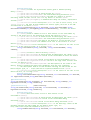
Each rule in a policy is specified by the PSML-P notation:
on(E) if (C) then (P) else (A), where:
-
on specifies the trigger of the rule, or when the rule is activated. Can be:
o true for continuous rules
OR
o the name of a registered event type in the SBC (see section 4 and figure 9).
A Registered event type is a public XML serializable event type (See section 4)
included in an assembly placed in the EventTypes folder of the SBC.
Examples: on(true) or on(SmokeOn), where SmokeOn is an event type included in the
VSmokeDetectorEvents.DLL located in the EventTypes folder(figure 9) of the SBC.
-
C specifies a condition which must be evaluated as a boolean (true/false).
P is a property which the system must hold. P holds one or more service calls, as specified
in section 5.2. P is a block of code which is executed if the condition C is evaluated to true
A is a block of code which follows the same convention as P. A is executed if C is evaluated
to false or if an exception occurs in the evaluation of C.
Expressions C, P and A are specified using C# and the SBC Service Calling convention specified in
section 5.2.
-
-
Policy files are specified as XML files stored in the Policies folder of the SBC. As with
schedules, the SBC checks for policy updates every 2 seconds:
o Once a new policy is added it is automatically registered for execution by the SBC
o Once an existing policy is modified, it is automatically re-loaded by the SBC
o Once an existing policy is deleted, it is automatically removed from execution by
the SBC
At each iteration (scan) of the Policies folder, the SBC automatically generates executable
code as follows:
o In the EventTypes folder, the EventSinkCode.cs file is generated, as illustrated in
figure 16. It contains policy enforcement code for all event-based policy rules and
specifies an event handler for each registered event type (see section 4 and figure
9)
o In the Policies folder, the ContinuousPolicy.cs file is generated, as illustrated in
figure 17. It contains policy enforcement code for all continous-rules specified by
all the policies in the Policy folder.
NOTE: For policies related to the same event type or for continuous rules, all the rules will be
chained together. Example:
Policy A:
on(Event) if(C1) then (P1) else (A1)
on(true) if(C2) then (P2) else (A2)
Policy B:
on(Event) if(C3) then (P3) else (A3)
on(true) if(C4) then (P4) else (A4)
Will result in the two policies being merged together as follows:
-
(EventSinkCode.cs):The event handler for the Event is a block of the form:
if(C1) then
try {P1} catch(){A1}
else A1;
if(C3) then
try {P3} catch(){A3}
else A3;
-
(ContinuousPolicy.cs): the continuos policy code will contain:
if(C2) then
try {P2} catch(){A2}
else A2;
if(C4) then
try {P4} catch(){A4}
else A4;
The XML format for specifying rules is given in the example below:
Figure 15 – Sample policy
Figure 16 – code generated from event-based policy rules
Figure 17- sample continuous policy code, generated from the continuous rule in figure 15
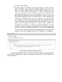
NOTE: for new policies to be installed, it is enough for a 3rd party service running on the same
machine as the SBC to write, modify or delete policy .XML files in the Policy folder.
Future versions of the SBC will include methods for enumerating, deleting and installing policies,
either in the same WCF service interface or using a separate service endpoint.
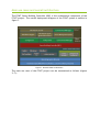
.
Policy scheduling
Scheduling policies can be done in the Web application through the SBC and
consists of attaching a schedule (functioning program) to a policy. The steps to
achieve this goal are:
• create a policy in the Policy Editor;
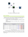
• view the policy in the web application by expanding the Policies section,
like below;
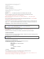
• pressing the "Create" button in the column "Schedule", button corresponding
to the current policy;
Policies Section
Viewing the policy in the Policies section
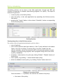
The section of the web application dedicated to policies allows :
• view all policies
• view current policies (see figure below): of the 7 policy defined in the above
figure, only one is running; a current policy is a policy loaded into the
current schedule, which is activated by SBC at startup and updated at each
change of the functioning program; such a program change can occur when
a policy is disabled;
• activation / deactivation of a policy by clicking "Enable"/ "Disable" button of
each policy;
• view a policy, by pressing "+" button beside each policy;
• attach a schedule to each policy, by clicking "Create" button next to it.
Display of current policies
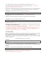
Once the button “+” is pressed, one can see the content of a policy:
• the name of the policy;
• the date of last change;
• the policy rules: for example, in the below figure, we have only one
rule, for “M001” policy, with the following clauses: Interval, On, If,
Then, the Else clause being null. The rules’ clauses are: the
“Interval” field indicates the duration in milliseconds between two
successive evaluation of the condition stated in the rule; the “On”
field indicates whether the rule is activated by an event or not; if the
last situation applies, the rule is continue; the “If” field describes the
condition to activate the rule (e.g., for the rule in the figure below,
the condition is that all the windows should be closed); the field
“Then” describes what happens when the condition is true: e.g.,
when all the windows are closed, we check a new condition; in
conclusion, the policies can contain nested verifications: the new
condition consists in checking the outside and the inside temperature,
the state of the air conditioning machine; if the outside temperature
is lower than 17 degrees and the inside temperature is lower than 22
degrees, bu the AC is stopped, then the AC is opened, at 30 degrees.
The content of a policy with one rule
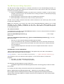
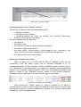
A policy with multiple rules is visible in the below figure. Note that the first
two rules are collapsed, the last two expanded, so each rule can be visualized in
tree-like manner.
The content of a policy with several rules
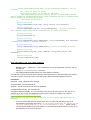
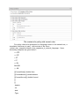
For policy rules to be presented in a language closer to the natural one, a
translation dictionary is used, with entries of the form :
<initial_char_sequence>blank><char_sequence_in_natural_language>. Some
dictionary examples are given below :
>= GTE
<= LTE
> GT
< LT
== EQ
&& AND
|| OR
[[CurrentHour]].double Hour
[[CurrentMinute]].double Minute
[[CurrentSecond]].double Second
[[
]]
.double
.int
.bool
.Type
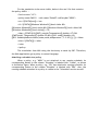
For the translation to be more visible, below is the xml file that contains
the policy «M001» :
<?xml version="1.0"?>
<policy name="M001"> -<rule name="Rule00" runEveryMs="30000">
<on><![CDATA[true]]></on>
<if><![CDATA[[[Windows.Window01]].bool==false &&
[[Windows.Window02]].bool==false && [[Windows.Window03]].bool==false &&
[[Windows.Window04]].bool==false]]></if>
<then><![CDATA[if(([[WiFI_outside.Temperature]].double<=17) &&
([[WIFInode1.Temperature]].double<22) && ([[AC1.state]].double==0))
[[AC1.SetMultipleDeviceState("state,mode,temperature","1~3~30")]]; ;]]></then>
<else><![CDATA[]]></else>
</rule>
</policy>
The translation from XML using the dictionary is made by SBC. Therefore,
the Web application get a policy in natural language.
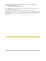
Attaching a schedule to a policy
When a policy, e.g. "M001" is not attached to any running schedule, its
corresponding button in the column "Schedule" is labeled with "Create", as shown
in the below figure. When a policy, e.g. "SP1" has attached a running schedule, its
corresponding button in the column "Schedule" is labeled with "Edit". Also, the
running schedule attached to a policy is visible in the "Schedules" section as well.
Relationship between a policy and its schedule
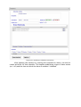
After clicking the "Create" button to build a schedule to a policy, a window
similar to that in the below figure will open : it is the same type of window that
opens when we want to create a schedule for a device, fact that gives consistency
to the web application. After opening the window for creating policy schedules, we
need to create activities for that schedule. This implies establishing a type of
action (activation / deactivation) for that policy and the time at which that policy
activates / deactivates itself.
Creating a schedule for a policy
After saving an action, we can see all the actions that form a functioning
program/schedule. For example, M001 policy, for which we have created a
program, respects the following rules of operation: every Tuesday, at 3, it is
turned on and at 5.01 it is turned off.
Creating a schedule action for a policy
Viewing the content of a policy schedule
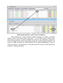
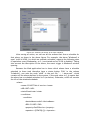
Attaching a policy schedule can only applies to policies for which the
current user has rights: e.g. in the Configurator window, the user "Maria" has
rights to all policies, except for one entitled "PC_Natalia_ECO_Policy" (surrounded
by red), which is not visible in the Web application. Moreover, the policy "SP1" has
a schedule "P SP1", both elements being visible to the user "maria", but if the user
did not have rights for the policy, he/she would not have rights for the policy
schedule either.
Display of policies taking into account the user's rights
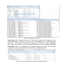
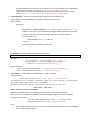
In order to know, in the web application, that some policies have a schedule
attached to them (so they have the “Edit” button the “Schedule” column), an
additional file "POLICIES.txt" is used, which stores the policy id and the policy
schedule id, in the format: <id_schedule>#<id_policy>. One should mention that
the policies ids start at 1, and the schedules ids start at 1224000: the
correspondence between IDs can be found below:
Connection between policies ids and their schedules ids
After attaching a schedule to a policy, this is recorded in the plan of
operation, which is called "schedule plan" in the context of FCINT system. It is
stored in txt and xml files that are read and executed by SBC. Below you can see
how these schedules are stored in the files used for SBC policies:
04.03.2013 14:35:00 ACTION:p[[ActivatePolicy("SP1")]] APPLIED_TO:4
DESCRIPTION:Policy State=ACTIVATE (Schedule: P SP1)
04.03.2013 15:40:00 ACTION:p[[DeactivatePolicy("SP1")]] APPLIED_TO:4
DESCRIPTION:Policy State=DEACTIVATE (Schedule: P SP1)
<?xml version="1.0"?>
<schedule_plans>
…..
<action>
<date>04.03.2013</date>
<hour>14:35:00</hour>
<applies_to>4</applies_to>
<description>PolicyState=ACTIVATE</description>
<powerConsumption>0</powerConsumption>
<schedule_name>P SP1</schedule_name>
</action>
<action>
<date>04.03.2013</date>
<hour>15:40:00</hour>
<applies_to>4</applies_to>
<description>PolicyState=DEACTIVATE</description>
<powerConsumption>0</powerConsumption>
<schedule_name>P SP1</schedule_name>
</action>
…..
</schedule_plans>
Interpretation of the above lines is: on 4th of March 2013, at 14.35, the
schedule by which policy «SP1» is activates is executed, on 4th of March 2013, at
15.40, the schedule by which policy «SP1» is deactivated is executed by SBC. In
addition to the information from the “txt” files, the “xml” files brings information
about the energy consumed by the created schedule.
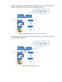
Scheduling policies is visible in the Web application, but it is made by the
SBC, as shown in the below figure: policies can be created / read / updated /
deleted (CRUD operations) only by political editor. Creating schedules for policies
is made only by SBC, via the Web. Charging the schedules in the operation plan
and subsequently their execution are also made by SBC.
The workflow for creating a policy schedule
Alarm scheduling
Planning for alarms can be achieved in Web application through the SBC and
consists of attaching a schedule to an alarm. The steps to achieve this goal are:
•
•
•
creating an alarm from the Alarms Configurator;
viewing the alarms from the Web application by expanding the Alarms
section;
pressing the "Create" button in the "Schedule" column, corresponding to
the current alarm.
Figure xx. Alarms Section
In the previous figure, we don’t have any active alarms; the «View Active
Alarms» button is deactivated and replaced with “No active alarms” label. When
the button is active, like in the next figure, one can see the alarms with the
«Active» status.
Figure xxx. The active alarms
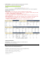
Visualizing alarms in the “Alarms” section
The section for alarms in the web application allows:
• viewing all alarms;
• viewing the active alarms;
• enabling/disabling an alarm by pressing the "Activate"/"Deactivate"
buttons, in the right of each alarm;
The data displayed for an alarm are:
• the alarm id ;
• the alarm name ;
• the device or service to which the alarm is applied ;
• the events triggering the alarm ;
• the alarm status : active/inactive, acknowledged or not - ack/unack ( the
state of ack/unack can be changed only from Alarms Configurator) ;
• the date and the hour of last change.
Attaching a schedule to an alarm
When an alarm, e.g. "1211991 Out of Service", applied to AC1 (an air
conditioner) from the below figure, has no schedule attached to it, its
corresponding button in the "Schedule" column is labeled "Create". When an alarm,
e.g. «Windows2" in the below figure, has attached a schedule, the corresponding
button in the "Schedule" column is labeled "Edit". Also, the schedule attached to an
alarm is visible in the "Schedules" section, similar to the policies schedules.
Schedules will be visible only if the user has the right to view them.
Figure xxx. The alarms with a schedule
After clicking the "Create" button to create a schedule for an alarm, a
window similar to that in below fogure will open (the same type of window that
opens when we want to create a schedule for a device or for a policy, which gives
consistency to the web application).
Figure xxx. Attaching a schedule to an alarm
After opening the window for creating the schedule for alarm, we need to
create activities for that schedule. This implies establishing a type of alarm action
(on / off) and the time at which the alarm is enabled / disabled.
Figure xxx. Attaching an action to an alarm schedule
After saving an action, we can see all the actions that form a schedule for
that alarm, as shown in the above figure. For example, the alarm "Windows3 is
open" (with id 1020), for which we created a schedule, respects the following rules
of operation: every Wednesday, at 9, is activated and at 20.00 is disabled. Taking
into account the description of the alarm, the event trigger is Windows3 window
opening.
Because the Web application has to know which alarms have a schedule
attached to them (and therefore have a status button "Edit" in the column
"Schedule"), one uses the node "schID" in the xml file "... / alarm.xml", which
contains all the alarms defined in the system. If the node value is 0, it means that
the alarm has no schedule attached to it (as below). Otherwise, schID will contain
the id's of the attached schedule.
<alarm>
<name>1211007 Out of service</name>
<AID>1007</AID>
<state>Deactivate</state>
<conditions>
<condition>
<deviceName>node9</deviceName>
<DID>1211007</DID>
<property>OutOfService</property>
<operator><![CDATA[=]]></operator>
<value>True</value>
</condition>
</conditions>
<status>Inactive Unack</status>
<time>3600</time>
<lastModified>28.02.2013 11:33:58</lastModified>
<activeUser>all</activeUser>
<schID>0</schID>
</alarm>
After attaching a schedule to an alarm, this is recorded in the plan of
operation, ie "plan schedule." It is stored in txt and xml files that are read by SBC
and executed accordingly. Below you can see what programs are running for
alarms stored in the files used by SBC:
04.03.2013 20:00:00 ACTION:a[[ActivateAlarm("1020")]] APPLIED_TO:1020
DESCRIPTION:Alarm State=ACTIVE (Schedule: Alarm 1020)
<action>
<date>04.03.2013</date>
<hour>20:00:00</hour>
<applies_to>1020</applies_to>
<description>AlarmState=ACTIVE</description>
<powerConsumption>0</powerConsumption>
<schedule_name>Alarm 1020</schedule_name>
</action>
Interpretation of the above lines is: on 4th of March 2013, at 20.00, the
schedule by which alarm with the id "1020" activate is executed. XML shows also
the energy consumed through the created schedule.