1
BricsCAD V14
User Guide
Table Of Contents
The BricsCAD Application Window ................................................. 1
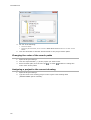
Open / Close the command bar .......................................................................................1
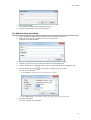
To set the command line properties .................................................................................2
Open / Close the status bar ............................................................................................3
Working with the status bar ...........................................................................................3
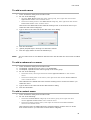
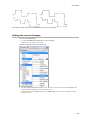
To customize the status bar ...........................................................................................5
Display or hide scroll bars ..............................................................................................6
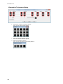
Toolbars ......................................................................................... 7
Toolbar Flyouts.............................................................................................................9
Opening a toolbar ....................................................................................................... 11
Closing a toolbar ........................................................................................................ 12
To set the icon size ..................................................................................................... 12
To set the position and visible property of a toolbar ......................................................... 12
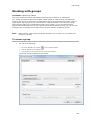
Prompt Menus .............................................................................. 13
To control the display of prompt menus ......................................................................... 13
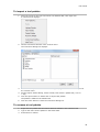
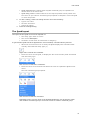
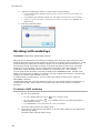
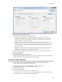
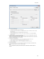
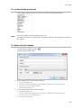
Properties Bar .............................................................................. 14
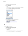
To open the Properties Bar ........................................................................................... 14
To adjust the size of the Properties Bar .......................................................................... 17
Setting the current properties in the Properties Bar ......................................................... 17
Edit the properties of a single entity .............................................................................. 18
To edit the endpoints of a line ...................................................................................... 19
To edit the vertices of a polyline ................................................................................... 20
Edit the shared properties of a selection set .................................................................... 21
Keyboard Shortcuts ..................................................................... 22
Model space and paper space ...................................................... 24
Understanding paper space and model space .................................................................. 24
Switching between model space and paper space ............................................................ 24
Using the model and layout tabs ................................................................................... 24
Toggle between model space and paper space in a layout ................................................. 25
Customizing BricsCAD .................................................................. 26
BricsCAD Startup Options ............................................................ 27
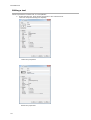
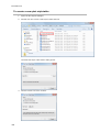
BricsCAD user files ....................................................................... 28
The BricsCAD user file manager .................................................................................... 29
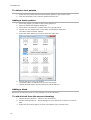
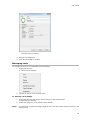
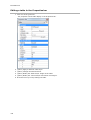
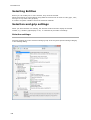
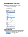
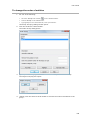
Understanding the Customize Dialog ........................................... 30
What are the CUI files ................................................................................................. 30
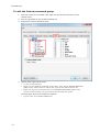
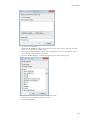
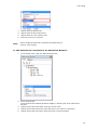
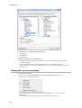
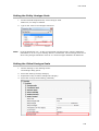
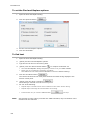
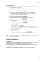
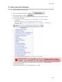
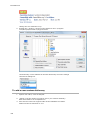
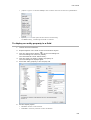
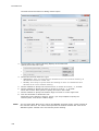
Opening the Customize dialog ...................................................................................... 30
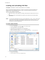
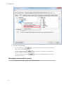
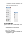
Loading and unloading CUI files .................................................. 32
To load a main CUI file ................................................................................................ 32
To load a partial CUI file .............................................................................................. 33
To unload a partial CUI file ........................................................................................... 33
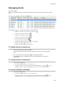
Managing customization groups .................................................................................... 34
iii
BricsCAD V14
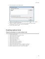
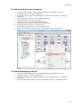
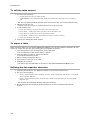
Creating custom tools .................................................................. 35
General procedure to create custom tools....................................................................... 35
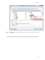
To create a Partial CUI file ........................................................................................... 36
To add a toolbox in a menu group ................................................................................. 36
To add a tool in a toolbox ............................................................................................ 37
To add a main menu ................................................................................................... 39
To add a submenu to a menu ....................................................................................... 39
To add a context menu ................................................................................................ 39
To add a toolbar ......................................................................................................... 42
To add a flyout to a toolbar .......................................................................................... 43
To add a control to a toolbar ........................................................................................ 44
To add a keyboard shortcut .......................................................................................... 44
To add an existing tool to a menu, toolbar or shortcut ...................................................... 45
To create a new tool in a menu, toolbar or shortcut ......................................................... 45
To change the order of the tools in a menu or toolbar ...................................................... 47
Tool Palettes ................................................................................ 47
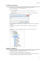
To open the Tool Palettes Bar ....................................................................................... 47
To set the view options ................................................................................................ 47
To add a new tool palette............................................................................................. 48
To import a tool palette ............................................................................................... 49
To rename a tool palette .............................................................................................. 49
To delete a tool palette ................................................................................................ 50
Adding a hatch pattern ................................................................................................ 50
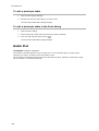
Adding a block ........................................................................................................... 50
To add a block from the current drawing: ....................................................................... 50
To add a block from any drawing: ................................................................................. 51
To add a drawing as a block: ........................................................................................ 51
Adding a command ..................................................................................................... 52
Editing a tool ............................................................................................................. 54
Managing tools ........................................................................................................... 55
Command Aliases......................................................................... 56
To edit the alias file in a text editor ............................................................................... 56
Using the Customize dialog to edit the alias file ............................................................... 57
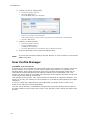
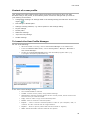
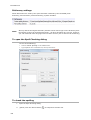
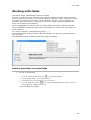
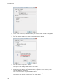
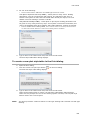
User Profile Manager ................................................................... 58
Content of a user profile .............................................................................................. 59
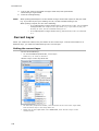
To Launch the User Profile Manager ............................................................................... 59
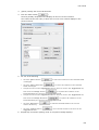
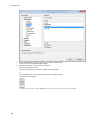
Creating user profiles .................................................................................................. 60
Starting BricsCAD with a specific user profile .................................................................. 60
Restarting BricsCAD using a different user profile ............................................................ 61
Managing user profiles................................................................................................. 62
To export a user profile ............................................................................................... 63
To import a user profile ............................................................................................... 63
To import a user profile from another user ..................................................................... 64
iv
Table of Contents
Projects ....................................................................................... 64
Opening the Project settings ......................................................................................... 64
Creating projects ........................................................................................................ 64
Adding search paths to a project ................................................................................... 65
Changing the order of the search paths .......................................................................... 66
Assigning a project to the current drawing...................................................................... 66
Drawing Accurately ..................................................................... 67
Using Orthogonal Mode................................................................ 67
To toggle Orthogonal Mode .......................................................................................... 67
Direct Distance Entry ................................................................... 68
To define the Coordinates setting .................................................................................. 68
Unit Settings ................................................................................ 68
Entering angles .......................................................................................................... 68
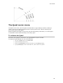
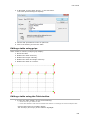
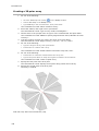
The Quad cursor menu ................................................................. 69
To activate the Quad ................................................................................................... 69
Editing the Quad settings ............................................................................................. 70
The Quad layout ......................................................................................................... 71
Customizing the Quad ................................................................................................. 72
To edit the workspace command groups ......................................................................... 72
To edit the Custom command group .............................................................................. 74
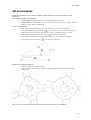
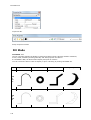
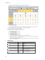
2D Constraints ............................................................................. 77
Commands and toolbars .............................................................................................. 78
Using Dimensional Constraints .................................................... 80
To edit dimensional constraints ..................................................................................... 80
Using expressions to define dimensional constraints ........................................................ 82
Using Geometric Constraints........................................................ 86
To control the display of constraint bars ......................................................................... 87
To control the position of a constraint bar....................................................................... 87
Working with the constraint bar .................................................................................... 88
Deleting constraints .................................................................................................... 88
Using fix constraints .................................................................................................... 89
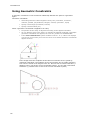
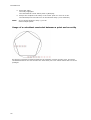
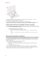
Using coincident constraints ......................................................................................... 89
To apply a coincident constraint between a point and an entity: ........................................ 89
Usage of a coincident constraint between a point and an entity ......................................... 90
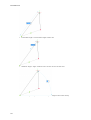
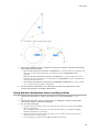
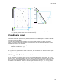
Using horizontal and vertical constraints ........................................................................ 92
To constrain a line to a fixed angle ................................................................................ 92
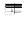
Dynamic Dimensions.................................................................... 93
Defining the Dynamic Dimensions Settings ..................................................................... 93
Using dynamic dimensions when creating entities ............................................................ 95
Using dynamic dimensions to grip-edit entities ................................................................ 96
Using dynamic dimensions to measure entities ................................................................ 96
v
BricsCAD V14
Coordinate Input ......................................................................... 97
Working with Cartesian coordinates ............................................................................... 97
Using relative Cartesian coordinates to draw a rectangle .................................................. 98
Working with cylindrical coordinates .............................................................................. 98
Working with spherical coordinates ................................................................................ 99
Using Snap and Grid .................................................................. 100
Display the Snap and Grid settings .............................................................................. 101
To synchronize snap and grid spacing .......................................................................... 101
To set the Drawing Limits .......................................................................................... 101
To toggle the Drawing Limits ...................................................................................... 101
Using Isometric Snap ................................................................................................ 101
Setting the Snap Angle .............................................................................................. 103
Entity Snaps............................................................................... 104
To define the Entity Snap settings ............................................................................... 104
To set the Entity Snaps.............................................................................................. 106
Entity Snap Modes .................................................................................................... 107
Working with multiple Entity Snap modes ..................................................................... 108
To snap to the extension of two entities ....................................................................... 108
Using the From option ............................................................................................... 109
Using the Parallel entity snap ..................................................................................... 109
Using Midpoint snap .................................................................................................. 109
Polar Tracking............................................................................ 110
To define the Polar Tracking settings ........................................................................... 110
Using Polar Tracking to draw a line .............................................................................. 111
Using Snap Track Lock .............................................................................................. 111
Using temporary tracking points ................................................................................. 111
Using the TT option ................................................................................................... 112
Using the TK option................................................................................................... 112
Entity Snap Tracking .................................................................. 113
Using Entity Snap Tracking......................................................................................... 113
User Coordinate Systems ........................................................... 115
Dynamic UCS ........................................................................................................... 116
To define a User Coordinate System ............................................................................ 117
To restore the WCS ................................................................................................... 117
To restore a UCS ...................................................................................................... 118
To set a relative UCS ................................................................................................. 118
Command Options .................................................................................................... 119
Measuring .................................................................................. 120
Measuring distances .................................................................................................. 120
Measuring lengths..................................................................................................... 121
Measuring areas ....................................................................................................... 122
vi
Table of Contents
Viewing Your Drawing ............................................................... 123
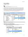
Layer Utilities ............................................................................ 125
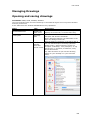
Redrawing and Regenerating a Drawing .................................... 126
Regenerate the current viewport ................................................................................. 126
Regenerate all viewports ............................................................................................ 126
Redraw the current viewport ...................................................................................... 126
Redraw all viewports ................................................................................................. 126
Panning ..................................................................................... 127
Using the pan command ............................................................................................ 127
Using real time panning ............................................................................................. 127
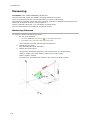
Zooming..................................................................................... 128
Using the zoom command .......................................................................................... 128
Real-time zooming .................................................................................................... 129
Dynamic zooming ..................................................................................................... 129
View manipulation using the mouse and keyboard .................... 130
Setting the Zoom Factor variable ................................................................................ 130
Setting the Middle Button Pan variable ......................................................................... 131
View Rotation ............................................................................ 131
Restoring orthographic and isometric views .................................................................. 131
Rotating a view freely................................................................................................ 132
Rotating a view about the view X-axis ......................................................................... 133
Rotating a view about the view Y-axis .......................................................................... 133
Rotating a view about the view Z-axis ......................................................................... 134
Using Preset Viewpoints ............................................................................................. 134
Restoring Plan View .................................................................................................. 136
Layer States ............................................................................... 137
Opening the Layer States Explorer .............................................................................. 137
To save the current layer state ................................................................................... 138
To edit a layer state .................................................................................................. 139
To restore a layer state ............................................................................................. 139
To copy layer states to another drawing ....................................................................... 139
To export a layer state .............................................................................................. 140
To import a layer state .............................................................................................. 140
Named Views ............................................................................. 141
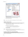
Exploring views ........................................................................................................ 141
Saving a view .......................................................................................................... 141
Restoring a view ....................................................................................................... 142
Defining the view background ..................................................................................... 143
To edit the view background....................................................................................... 145
Workspaces ............................................................................... 145
Managing workspaces................................................................................................ 145
Setting the current workspace .................................................................................... 146
Creating a workspace ................................................................................................ 147
Editing a workspace .................................................................................................. 147
Deleting a workspace ................................................................................................ 148
vii
BricsCAD V14
Define a View ............................................................................. 149
Defining a camera view ............................................................................................. 150
To toggle the perspective property of view ................................................................... 151
Model space and paper space .................................................... 151
Switching between model space and paper space .......................................................... 152
Using the model and layout tabs ................................................................................. 152
Toggle between model space and paper space in a layout ............................................... 152
Model Space Viewports .............................................................. 153
Creating viewports in model space .............................................................................. 153
Drawing in multiple viewports ..................................................................................... 155
Joining adjacent viewports ......................................................................................... 155
Paper space viewports ............................................................... 156
Displaying the paper sheet and the printable area ......................................................... 157
Creating viewports in a layout .................................................................................... 157
Creating an array of layout viewports .......................................................................... 160
To clip a viewport ..................................................................................................... 161
To remove the clipping boundary of a viewport ............................................................. 161
Defining viewport properties ....................................................................................... 162
Properties ................................................................................................................ 163
Navigating in a paper space layout .............................................................................. 164
Setting the layer visibility in a viewport ........................................................................ 164
Setting the scale of a viewport .................................................................................... 164
Setting the scale of a selection of viewports .................................................................. 165
To rotate the display in a viewport .............................................................................. 165
Rotating the viewport display ..................................................................................... 165
Defining the rotation angle of the viewport display ........................................................ 166
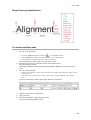
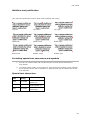
To align viewports..................................................................................................... 166
To align model space and paper space points ................................................................ 167
Aligning 1 point ........................................................................................................ 167
Aligning 2 points ....................................................................................................... 167
Layouts ...................................................................................... 168
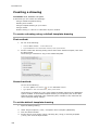
Creating a new layout ............................................................................................... 168
Copying layouts ........................................................................................................ 168
Importing layouts ..................................................................................................... 168
Renaming layouts ..................................................................................................... 169
Arranging the layout tabs........................................................................................... 169
Deleting a layout ...................................................................................................... 169
Generated Drawing Views .......................................................... 170
Commands and Toolbars............................................................................................ 171
Standard Drawing Views ............................................................................................ 171
Generating Cross Section Views .................................................................................. 173
Updating Drawing Views ............................................................................................ 173
Exporting Views to Model Space .................................................................................. 174
Customizing Drawing Views ........................................................................................ 174
Drawing Entities ........................................................................ 175
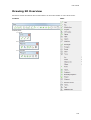
Overview ................................................................................................................. 175
viii
Table of Contents
Fill Mode .................................................................................... 176
Setting Fill Mode ....................................................................................................... 177
Entity Color ................................................................................ 177
Index Colors .............................................................................................................. 177
True Colors ................................................................................................................ 178
Setting the current entity color ................................................................................... 179
Lineweight ................................................................................. 180
Setting the current lineweight ..................................................................................... 180
Defining the lineweight settings .................................................................................. 181
Entity Linetype........................................................................... 182
Setting the current linetype ........................................................................................ 183
Adding a new linetype ............................................................................................... 184
Setting the Entity Linetype Scale ................................................................................. 185
Setting the Global Linetype Scale ................................................................................ 185
Current Layer ............................................................................. 186
Setting the current layer ............................................................................................ 186
Drawing 2D Overview ................................................................ 187
Arcs ........................................................................................... 189
General procedure to draw an arc ............................................................................... 189
Editing an arc ........................................................................................................... 189
Circles ........................................................................................ 190
General procedure to draw a circle .............................................................................. 190
Editing a circle ......................................................................................................... 191
Ellipses ...................................................................................... 191
Setting the Polyline Ellipse (PELLIPSE) system variable .................................................. 192
General procedure to draw an ellipse ........................................................................... 192
Editing an ellipse ...................................................................................................... 193
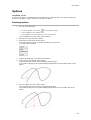
Elliptical Arcs ............................................................................. 194
General procedure to draw an elliptical arc ................................................................... 194
Editing an elliptical arc .............................................................................................. 195
Freehand sketches ..................................................................... 195
Setting the Sketch Poly (SKPOLY) system variable ......................................................... 196
Creating a freehand sketch ........................................................................................ 196
Infinite Lines ............................................................................. 197
Drawing infinite lines ................................................................................................. 197
Lines .......................................................................................... 198
Drawing lines ........................................................................................................... 198
Solids ......................................................................................... 199
Drawing solids .......................................................................................................... 199
Points ........................................................................................ 200
Defining the point display settings ............................................................................... 200
Drawing points ......................................................................................................... 201
ix
BricsCAD V14
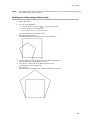
Polygons .................................................................................... 201
Drawing polygons ..................................................................................................... 202
Polylines .................................................................................... 202
Drawing polylines ..................................................................................................... 203
Creating boundary polylines ....................................................................................... 205
Rays ........................................................................................... 207
Drawing rays ........................................................................................................... 207
Rectangles ................................................................................. 207
Drawing rectangles ................................................................................................... 208
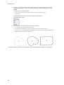
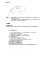
Revision Clouds ......................................................................... 208
Drawing revision clouds ............................................................................................. 209
Splines ....................................................................................... 211
Drawing splines ........................................................................................................ 211
Traces ........................................................................................ 212
Drawing traces ......................................................................................................... 212
Wipeouts ................................................................................... 213
To create a wipeout using points ................................................................................. 213
To create a wipeout from a polyline ............................................................................. 213
To control the display of the edges of wipeouts ............................................................. 214
Mechanical ................................................................................. 215
Components and Component Inserts ......................................................................... 215
Commands and Toolbars ........................................................................................... 215
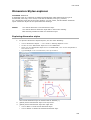
Mechanical Browser................................................................................................... 216
Bill Of Materials ......................................................................................................... 217
Organizing Geometry in Components ........................................................................ 217
Changing Mechanical Structure ................................................................................... 218
Using Standard Hardware .......................................................................................... 218
Assembly Constraints ................................................................................................ 218
Component Visibility ................................................................................................. 218
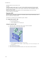
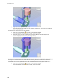
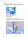
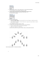
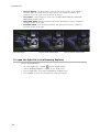
Assembly Design and Kinematic Analysis Tutorial ..................................................... 219
Step 1: Preparing for the exercise ............................................................................... 219
Step 2: Creating the assembly drawing ........................................................................ 221
Step 3: Adding the components .................................................................................. 221
Step 4: Positioning the components............................................................................. 223
Step 5: Preparing for the kinematic analysis ................................................................. 229
Step 6: Kinematic Analysis ......................................................................................... 232
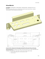
SheetMetal ................................................................................. 233
Sheet Metal Features................................................................................................. 234
Bend Table .............................................................................................................. 235
The Mechanical Browser for Sheet Metal....................................................................... 238
Commands and Toolbars............................................................................................ 239
Sheet Modeling Operations ........................................................................................ 240
Creating the Base Flange ........................................................................................... 240
Creating Edge Flanges ............................................................................................... 241
Corner Reliefs and Junctions ....................................................................................... 243
x
Table of Contents
To Rotate a Flange .................................................................................................... 244
To connect flanges .................................................................................................... 244
Changing the Thickness ............................................................................................. 244
Changing the bend radius .......................................................................................... 245
To change the overall bend radius: .............................................................................. 245
To change the bend radius for a particular bend: ........................................................... 245
To Unfold the Sheet Metal Body .................................................................................. 246
Direct Modeling Overview .......................................................... 247
3D Constraints ........................................................................... 247
Variational Direct Modeling ......................................................................................... 247
Mechanical Browser .................................................................................................. 248
3D Constraints types ................................................................................................. 248
3D Constraints and Direct Modeling ............................................................................. 248
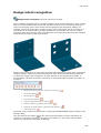
Design intent recognition........................................................... 249
Direct Modeling operations ........................................................ 253
Selecting geometry.................................................................................................... 254
To control dimensions ............................................................................................... 254
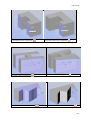
Making holes ............................................................................................................ 254
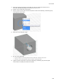
To make a (circular) hole through a solid ..................................................................... 254
Deleting holes. ......................................................................................................... 256
To delete a circular hole............................................................................................. 256
To delete a rectangular hole ....................................................................................... 257
Working with sections ............................................................... 258
To launch the Sectionplane command .......................................................................... 258
Align a section plane to a face .................................................................................... 258
To create a vertical section plane ................................................................................ 258
To create a horizontal section plane............................................................................. 259
To create a vertical jogged section plane ...................................................................... 260
To create a horizontal jogged section plane .................................................................. 260
To create a orthographic section plane ......................................................................... 261
To open the Drawing Explorer - Section Planes dialog .................................................... 262
To edit the properties of a section plane ....................................................................... 262
To modify the size and position of a section plane ......................................................... 263
Using Live Section .................................................................................................... 264
To set the Live Section property of a section plane: ....................................................... 264
To define the live section settings ............................................................................... 265
To save a section ...................................................................................................... 266
To launch the SectionPlaneToBlock command ............................................................... 266
To insert a section as a 2D block ................................................................................. 267
To insert a section as a 3D block ................................................................................. 267
To replace an existing block ....................................................................................... 267
To export a section to a file ........................................................................................ 268
Hatching .................................................................................... 269
Defining the MEASUREMENT setting ............................................................................ 269
Defining the MAXHATCH setting .................................................................................. 269
xi
BricsCAD V14
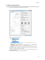
Creating Hatches and Gradient Fills ........................................... 270
General procedure to create hatches and gradient fills ................................................... 270
To define hatch properties.......................................................................................... 271
To define gradient fill properties.................................................................................. 273
To define the boundary for a hatch or gradient fill ......................................................... 274
Editing a hatch or gradient fill ................................................... 275
To edit a hatch or gradient fill in the properties bar ........................................................ 275
To edit a hatch in a dialog box .................................................................................... 276
To edit a gradient fill in a dialog box ............................................................................ 277
Dimensions ................................................................................ 279
Dimensioning Concepts.............................................................. 279
Dimension Style ....................................................................................................... 279
Dimension Block ....................................................................................................... 280
Dimensioning tools overview ..................................................... 281
Dimension Styles explorer ......................................................... 283
Exploring dimension styles ......................................................................................... 283
Associative Dimensions ............................................................. 284
Dimension Settings .................................................................... 285
To list the current status of the dimension variables....................................................... 285
Lines and Arrows ...................................................................................................... 285
Text........................................................................................................................ 286
Fit .......................................................................................................................... 288
Primary Units ........................................................................................................... 288
Alternate Units ......................................................................................................... 289
Tolerances ............................................................................................................... 289
Dimension Styles explorer ......................................................... 290
Exploring dimension styles ......................................................................................... 290
Creating linear dimensions ........................................................ 292
To create a horizontal or vertical linear dimension ......................................................... 292
To create an aligned linear dimension .......................................................................... 292
To create a rotated linear dimension ............................................................................ 293
To create baseline dimensions .................................................................................... 293
To create continued dimensions .................................................................................. 294
To create an arc length dimension ............................................................................... 294
Creating angular dimensions ..................................................... 295
To dimension an angle between two lines ..................................................................... 295
To dimension an angle encompassed by an arc ............................................................. 296
To create an angular dimension defined by a vertex and two endpoints ............................ 296
To create a diametrical dimension ............................................................................... 297
To create a radial dimension....................................................................................... 297
Creating center marks or center lines .......................................................................... 297
Creating ordinate dimensions .................................................... 298
To create an ordinate dimension ................................................................................. 298
xii
Table of Contents
Creating leaders and annotations .............................................. 298
To create a leader and an annotation ........................................................................... 298
To create a leader only .............................................................................................. 299
Editing dimensions .................................................................... 300
Using grips to edit a linear dimension .......................................................................... 300
Editing the dimension text ......................................................................................... 301
To edit the dimension text in the MText editor .............................................................. 301
To edit the dimension text in the Properties Bar ............................................................ 301
To edit the dimension text using the Edit Dimension Text tool ......................................... 301
To rotate the dimension text ...................................................................................... 302
To reposition the dimension text ................................................................................. 302
To restore the text position ........................................................................................ 302
To make the extension lines oblique ............................................................................ 302
Adding Geometric Tolerances .................................................... 303
To create a geometrical tolerance frame....................................................................... 303
Geometric Tolerance dialog ........................................................................................ 304
Working with Texts .................................................................... 305
Text Styles .............................................................................................................. 305
Text Font ................................................................................................................. 305
Text Variables ............................................................................ 305
Text styles ................................................................................. 306
To open the Text Style Explorer dialog ......................................................................... 306
To create a text style ................................................................................................ 306
To edit a text style .................................................................................................... 307
To make a text style current....................................................................................... 307
To delete a text style ................................................................................................ 307
Creating text .............................................................................. 308
To create single line text ............................................................................................ 308
Single line text justification ........................................................................................ 309
To create multiline text .............................................................................................. 309
Text formatting toolbar tools and settings .................................................................... 310
Multiline text justification ........................................................................................... 311
Including special text characters and symbols ............................................................... 311
Special text characters .............................................................................................. 311
Symbols and Unicode strings ...................................................................................... 312
To add a background mask ........................................................................................ 312
Editing text ................................................................................ 313
To edit a text entity .................................................................................................. 313
To edit a selection of Mtext entities ............................................................................. 313
To select a different multiline text editor ...................................................................... 314
Exploding text............................................................................ 314
To explode text ........................................................................................................ 314
xiii
BricsCAD V14
Finding and replacing text ......................................................... 314
To open the Find and Replace dialog ............................................................................ 315
To set the Find and Replace options ............................................................................ 316
To find text .............................................................................................................. 316
To replace text ......................................................................................................... 317
Checking Spelling ...................................................................... 317
Dictionary settings .................................................................................................... 318
To open the Spell Checking dialog ............................................................................... 318
To check the spelling ................................................................................................. 318
To change dictionaries ............................................................................................... 320
To add a new main dictionary ..................................................................................... 321
To add a new custom dictionary .................................................................................. 322
Working with Fields ................................................................... 323
General procedure to create fields ............................................................................... 323
To display an entity property in a field ......................................................................... 325
To edit a field ........................................................................................................... 326
To update a field ...................................................................................................... 326
To convert a field to text ............................................................................................ 326
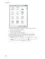
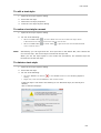
Tables ........................................................................................ 327
To create an empty table ........................................................................................... 327
To create a table from data ........................................................................................ 328
To create a table from an Excel spreadsheet ................................................................. 328
Editing a table using grips .......................................................................................... 329
Editing a table using the Table toolbar ......................................................................... 329
Table tools ............................................................................................................... 330
Editing a table in the Properties bar ............................................................................. 332
Editing a cell in the Properties bar ............................................................................... 333
To edit the table content ............................................................................................ 334
To export a table ...................................................................................................... 334
Defining the list separator character ............................................................................ 334
Table Styles ............................................................................... 336
To open the Table Styles Explorer ............................................................................... 336
To create a table style ............................................................................................... 336
To edit a table style .................................................................................................. 337
To apply a style to a table .......................................................................................... 337
To delete a table style ............................................................................................... 337
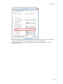
Modifying Commands Overview ................................................. 338
Entity Modification Settings ....................................................... 339
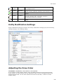
Adjusting the Draw Order .......................................................... 339
Using Draw Order ..................................................................................................... 340
Using Draw Order tools .............................................................................................. 340
xiv
Table of Contents
Grips editing .............................................................................. 341
Selecting multiple grips ............................................................................................. 341
Grip Edit Command Options ....................................................................................... 342
To stretch entities using grips ..................................................................................... 342
To move entities using grips ....................................................................................... 342
To copy entities using grips ........................................................................................ 343
To mirror entities using grips ...................................................................................... 343
To rotate entities using grips ...................................................................................... 344
To scale entities using grips ....................................................................................... 345
Selecting Entities ....................................................................... 346
Selection and grip settings ........................................................ 346
Selection settings ..................................................................................................... 346
Grips settings ........................................................................................................... 348
Selection Methods ...................................................................... 349
Composing a selection set before (pre-pick) ................................................................. 350
Composing a selection set afterwards (post-pick) .......................................................... 350
Selecting overlapping entities ..................................................................................... 351
Quick Select ............................................................................... 352
To create a selection set ............................................................................................ 352
Rearranging Entities .................................................................. 357
Moving Entities .......................................................................... 357
Moving entities in a drawing...................................................................................... 357
Using the Move command .......................................................................................... 357
Moving entities using grips ......................................................................................... 358
Moving entities between drawings ............................................................................ 359
Using Cut and Paste to move entities between drawings ................................................. 359
Move a selection as a block ........................................................................................ 359
Rotating Entities ........................................................................ 360
Rotating a selection set ............................................................................................. 360
Rotating a selection set in reference to a base angle ...................................................... 361
Rotating in 3D .......................................................................................................... 361
Mirroring Entities ....................................................................... 362
Mirroring entities about a line ..................................................................................... 362
Mirroring entities about a plane .................................................................................. 362
Aligning Entities......................................................................... 363
Aligning an entity in 2D ............................................................................................. 363
Aligning an entity in 3D ............................................................................................. 364
Changing Entities ....................................................................... 366
To change text entities .............................................................................................. 366
To relocate blocks ..................................................................................................... 366
xv
BricsCAD V14
Copying Entities ......................................................................... 367
Copying Entities in a Drawing .................................................... 367
To copy a selection set .............................................................................................. 367
To make multiple copies ............................................................................................ 368
To paste a selection set as a block .............................................................................. 368
Copying Entities Between Drawings........................................... 369
Using Copy and Paste to copy entities between drawings ................................................ 369
Using Copy and Pasteorig to copy entities between drawings ........................................... 370
Using Copybase and Paste to copy entities between drawings ......................................... 370
Paste a selection as a block in the target drawing .......................................................... 370
Making Parallel Copies ............................................................... 371
Making a parallel copy at a specified distance ............................................................... 371
Making a parallel copy through a point ......................................................................... 372
Arraying Entities ........................................................................ 372
Creating a rectangular array ....................................................................................... 372
Creating a polar array ............................................................................................... 374
Arraying Entities in 3D ............................................................... 376
Creating a 3D rectangular array .................................................................................. 376
Creating a 3D polar array........................................................................................... 378
Resizing Entities ........................................................................ 379
Extending Entities ...................................................................... 379
To extend entities ..................................................................................................... 379
Trimming Entities ...................................................................... 380
To trim entities ......................................................................................................... 380
Changing the length of an entity ................................................ 381
Change the length of an entity dynamically .................................................................. 381
Modify the included angle of an arc ............................................................................. 382
Stretching Entities ..................................................................... 383
To stretch entities ..................................................................................................... 383
Stretching entities using grips .................................................................................... 384
Scaling Entities .......................................................................... 384
To scale a selection set .............................................................................................. 384
Scaling an entity using a base scale............................................................................. 385
Breaking Entities ....................................................................... 386
To break an entity .................................................................................................... 386
Joining Entities .......................................................................... 386
To join colinear lines ................................................................................................. 386
To join two arcs ........................................................................................................ 387
Chamfering and Filetting ........................................................... 388
Chamfer and fillet settings ......................................................................................... 388
xvi
Table of Contents
Chamfering Entities ................................................................... 389
Chamfering using the distance-distance method ............................................................ 389
Chamfering using the length-angle method .................................................................. 390
Chamfering all vertices of a polyline ............................................................................ 391
Filleting Entities ......................................................................... 392
Filleting two entities or polyline segments .................................................................... 392
Filleting all vertices of a polyline ................................................................................. 393
Filleting two parallel lines ........................................................................................... 394
Editing Polylines ........................................................................ 395
Converting an entity into a polyline ........................................... 395
Converting an entity into a polyline ............................................................................. 395
Opening and closing polylines ................................................... 396
To close or open a polyline ......................................................................................... 396
Opening and closing a polyline using the BricsCAD Properties bar .................................... 396
Joining Polylines ........................................................................ 397
To join an arc, line, or polyline to an existing polyline .................................................... 397
Changing the polyline width ...................................................... 398
To apply a uniform width to a polyline ......................................................................... 398
To taper a polyline uniformly along its length ................................................................ 398
Editing polyline vertices............................................................. 399
Editing a polyline using the Quad ................................................................................ 399
Starting the polyline vertex editing mode ..................................................................... 400
Convert a straight polyline segment into an arc ............................................................. 400
Break a polyline into two separate polylines .................................................................. 401
Insert a new vertex in a polyline ................................................................................. 401
Move a vertex in a polyline......................................................................................... 402
Delete vertices in a polyline........................................................................................ 402
Change the width of a polyline segment ....................................................................... 402
Curving and decurving polylines ................................................ 403
To fit a curve to a polyline.......................................................................................... 403
Setting the Linetype generation mode ....................................... 404
To set the Linetype mode ........................................................................................... 404
Editing polylines in the Properties bar ....................................... 406
To move polyline vertices........................................................................................... 406
To change the width of polyline segments ................................................................... 407
To convert straight segments into a curve .................................................................... 407
Converting Entities .................................................................... 408
Exploding entities ...................................................................... 408
To explode entities .................................................................................................... 408
Creating Regions ....................................................................... 409
To create regions ...................................................................................................... 409
xvii
BricsCAD V14
Measuring and Dividing Entities ................................................. 410
Measuring Entities ..................................................................... 410
To measure an entity using points ............................................................................... 410
To place blocks a specified interval along an entity ........................................................ 410
Dividing Entities......................................................................... 412
To divide an entity using points .................................................................................. 412
To divide an entity using blocks .................................................................................. 412
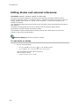
Blocks, attributes and external references ................................ 414
Blocks ..................................................................................................................... 414
Attributes ................................................................................................................ 414
External references ................................................................................................... 414
Blocks ........................................................................................ 414
Creating Blocks .......................................................................... 415
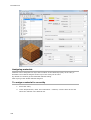
General procedure to create a block ............................................................................ 415
To create a block in a drawing .................................................................................... 415
To create a block using the Blocks Explorer .................................................................. 416
To save a block to a separate file ................................................................................ 417
Inserting Blocks......................................................................... 419
General procedure to insert a block: ............................................................................ 419
To insert a block ....................................................................................................... 420
To insert a block using the Drawing Explorer................................................................. 421
Inserting internal blocks ............................................................................................ 421
Inserting blocks from another drawing ......................................................................... 422
To insert a block aligned with an entity ........................................................................ 423
To insert multiple instances of a block in a rectangular array ........................................... 424
Redefining Blocks ...................................................................... 425
To redefine an internal block definition ......................................................................... 425
To reload an external drawing as a block ...................................................................... 426
Exploring Blocks ........................................................................ 427
Open the Blocks Explorer ........................................................................................... 427
The Blocks Explorer display options .......................................................................... 427
Open the Detail View of the Blocks Explorer .................................................................. 428
Open the Icon View of the Blocks Explorer .................................................................... 428
To rename a block .................................................................................................... 429
Exploding Blocks ........................................................................ 429
To explode a block .................................................................................................... 429
Setting the Explodable property of a block .................................................................... 429
Dynamic Blocks.......................................................................... 430
Editing dynamic blocks .............................................................................................. 430
Working with attributes ............................................................. 431
General procedure to work with attributes .................................................................... 431
xviii
Table of Contents
Defining Attributes .................................................................... 431
General procedure to define attributes: ........................................................................ 431
To define an attribute ................................................................................................ 431
Using sheet set properties in a title block ..................................................................... 433
Editing attribute definitions ....................................................... 434
To edit tag, prompt or default text of an attribute .......................................................... 434
To edit an attribute definition ..................................................................................... 435
Placing blocks with attributes .................................................... 436
To place a block with attributes .................................................................................. 436
Editing attributes attached to blocks ......................................... 437
Using the Attribute Editor........................................................................................... 437
Editing attributes in the Properties bar ......................................................................... 438
Extracting attribute information ................................................ 439
To extract attribute information .................................................................................. 440
Working with external references .............................................. 441
Attaching an external reference ................................................ 441
To attach an external reference .................................................................................. 441
Managing Xrefs .......................................................................... 443
To detach external references ..................................................................................... 443
To unload external references ..................................................................................... 443
To reload external references ..................................................................................... 443
Editing blocks and external references ...................................... 444
To edit Xrefs or blocks ............................................................................................... 444
Working with groups ................................................................. 447
To create a group ..................................................................................................... 447
To modify a group .................................................................................................... 448
To ungroup entities ................................................................................................... 448
To change the order of entities ................................................................................... 449
Working with underlays ............................................................. 450
To attach a PDF underlay ........................................................................................... 450
To insert a PDF underlay ............................................................................................ 451
To control the display of a PDF underlay....................................................................... 452
To set the layer display in a PDF underlay .................................................................... 452
To clip a PDF underlay ............................................................................................... 454
To toggle the display of the clipped part of a PDF underlay ............................................. 454
To delete a clipping boundary ..................................................................................... 455
Exploring Images ....................................................................... 456
Open the Images Explorer ......................................................................................... 456
Images Explorer display options ............................................................................... 456
Open the Detail View of the Images Explorer ................................................................ 457
Open the Icon View of the Images Explorer .................................................................. 457
Open the Tree View of the Images Explorer .................................................................. 458
Placing images in a drawing ...................................................................................... 458
xix
BricsCAD V14
Load / Unload images................................................................................................ 460
Load / Unload a single image ...................................................................................... 460
Load / Unload multiple images .................................................................................... 460
Removing images ...................................................................................................... 461
Detach images ......................................................................................................... 461
Image Utilities ........................................................................... 462
To set the image transparency .................................................................................... 462
Modify the Image Frame setting.................................................................................. 462
To clip an image ....................................................................................................... 463
To toggle the clipping boundary of an image ................................................................. 463
Printing ...................................................................................... 464
To open the Print dialog ............................................................................................. 465
To choose the paper size ........................................................................................... 465
To choose the paper units .......................................................................................... 466
To choose the paper orientation .................................................................................. 466
To define the plot offset ............................................................................................. 466
To specify the area to plot.......................................................................................... 467
To define the plot scale.............................................................................................. 467
To set the plot options ............................................................................................... 468
To set the shade plot mode ........................................................................................ 469
To define the plot stamp ............................................................................................ 469
Variables ................................................................................................................. 470
To specify the number of copies .................................................................................. 470
To see a preview of the plot output ............................................................................. 471
Plotter Configuration ................................................................. 471
To create a plotter configuration file ............................................................................ 471
To edit a plotter configuration ..................................................................................... 473
To assign a plotter configuration ................................................................................. 473
Plot Style tables ......................................................................... 474
Color-dependent plot style tables (CTB file) .................................................................. 474
Named plot style tables (STB file) ............................................................................... 474
Predefined plot styles ................................................................................................ 474
Changing Plot Style Table Types ................................................................................ 475
To convert a drawing from STB to CTB file type ............................................................. 475
To convert a drawing from CTB to STB file type ............................................................. 475
To convert a Color-dependent plot style table (CTB) to a Named plot style table (STB) ....... 475
The Plot Style Table editor ......................................................... 476
To open the Plot Style Table editor .............................................................................. 476
The General tab........................................................................................................ 477
The Form View tab .................................................................................................... 477
The Lineweights tab .................................................................................................. 479
Assigning plot style tables ......................................................... 480
To assign a plot style table ......................................................................................... 480
Toggling the plot style table on/off ........................................................................... 481
xx
Table of Contents
The Plot Styles Manager ............................................................ 481
To open the Plot Styles Manager ................................................................................. 481
To create a new plot style table .................................................................................. 482
To create a new plot style table in the Print dialog ......................................................... 483
To edit a plot style table ............................................................................................ 484
To edit a plot style table in the Print dialog ................................................................... 484
Batch Plot .................................................................................. 484
Managing Drawings ................................................................... 485
Opening and saving drawings .................................................... 485
Using the Drag-and-Drop option menu ......................................................................... 488
Getting drawing information ...................................................... 489
General drawing information ...................................................................................... 489
Information about entities .......................................................................................... 489
Creating a drawing .................................................................... 490
To create a drawing using a default template drawing .................................................... 490
First method: ........................................................................................................... 490
Second method: ....................................................................................................... 490
To set the default template drawing ............................................................................ 490
To create a drawing from scratch ................................................................................ 491
To set the Plot style policy ......................................................................................... 492
To create a drawing using a template drawing .............................................................. 492
To create a drawing using the New command ............................................................... 492
To set the Template Path variable ............................................................................... 493
To create a drawing using a wizard.............................................................................. 493
Drawing Explorer ....................................................................... 495
To open the Drawing Explorer..................................................................................... 496
To control the Drawing Explorer layout ........................................................................ 497
Opening a drawing .................................................................................................... 497
Adding a drawing folder ............................................................................................. 498
To insert a block from an unopened drawing ................................................................. 498
To copy definitions between drawings .......................................................................... 499
To merge the content of two layers ............................................................................. 499
Repairing a drawing................................................................... 499
To analyze the integrity of the current drawing ............................................................. 499
To repair a drawing ................................................................................................... 500
Drawing Properties .................................................................... 500
To open the Drawing Properties dialog ......................................................................... 500
Defining default properties ......................................................................................... 501
Adding custom properties .......................................................................................... 502
Drawing Security Options .......................................................... 502
To set the password .................................................................................................. 502
To remove the password ............................................................................................ 503
Export to PDF ............................................................................. 503
Export to PDF settings ............................................................................................... 503
Exporting a drawing to PDF ........................................................................................ 504
xxi
BricsCAD V14
Etransmit ................................................................................... 505
Digitizing Tablet......................................................................... 505
To use a digitizing tablet in BricsCAD ........................................................................... 505
To download the tablet overlay and CUI files................................................................. 506
To load the overlay CUI file ........................................................................................ 507
To switch the tablet ON / OFF ..................................................................................... 507
To Configure the tablet .............................................................................................. 507
To calibrate the tablet ............................................................................................... 508
Rendering .................................................................................. 511
Setting the render preferences ................................................................................... 511
Rendering tools ........................................................................................................ 512
To render a viewport ................................................................................................. 513
To save a rendering to a file ....................................................................................... 513
Rendering Materials ................................................................... 514
Materials glossary ..................................................................................................... 514
Defining materials..................................................................................................... 517
Assigning materials ................................................................................................... 518
To assign a material to an entity ................................................................................. 518
To assign a material to a layer .................................................................................... 519
Lights......................................................................................... 519
Lighting glossary ...................................................................................................... 519
General properties .................................................................................................... 520
Spotlight hotspot and falloff properties......................................................................... 520
Photometric properties .............................................................................................. 521
Geometry properties ................................................................................................. 521
Attenuation properties ............................................................................................... 521
To open the light list in the Drawing Explorer ................................................................ 522
To define a light ....................................................................................................... 524
To edit a light........................................................................................................... 525
To define the sun properties ....................................................................................... 526
To define the geographic location ................................................................................ 526
xxii
The BricsCAD Application Window
The layout of the BricsCAD application window can be fully customized.
You can:
open / close the command window
open / close the status bar
customize the status bar
modify drawing settings in the status bar
display / hide scroll bars
Components of the BricsCAD application window:
1.
Menu Bar
2.
Toolbar (docked)
3.
Drawing windows
4.
Drawing viewports
5.
Properties Bar
6.
Toolbar (floating)
7.
Command bar
8.
Status Bar
9.
Prompt Menu
Open / Close the command bar
Do one of the following:
Choose Command Bar in the View Menu.
Move the cursor to a docked toolbar, then right click and choose Command Bar
in the context menu.
Double click the Status field at the left hand side of the Status Bar.
The Command Window closes if it was open and vice versa.
1
BricsCAD V14
1.
Close button
2.
Press and hold the left mouse button to move the command bar
3.
Command History List field: the content of the history list field can be copied to the
command edit field.
4.
Command Edit field
If the Enable flag of the AUTOCOMPLETEMODE system variable is set, command
entries are completed automatically.
Do one of the following:
Press Enter if the currently completed command displays.
Choose a command in the Suggestion list.
Autocomplete options are:
5.
NOTES
Command history scroll buttons
You can modify the height of the docked command window by dragging its top
edge, when docked Lower or bottom edge, when docked Upper.
The size of a floating command bar can be adjusted by dragging one of its
edges.
When the command bar is closed, command options and keyboard entries
display in the status bar.
Use the arrow-up and arrow-down keys of the keyboard to browse the command
history.
To set the command line properties
1.
2
Open the Settings window.
User Guide
2.
Go to Program Options / User Preferences / Command Line.
Open / Close the status bar
Do one of the following:
Choose Status Bar in the View Menu.
Press the Shift + F3 keyboard shortcut.
The Status Bar closes if it was open and vice versa.
Working with the status bar
The Status Bar fields are:
1.
2.
3.
4.
5.
Status:
displays the status of the software.
when the cursor is in a menu or on a toolbar: gives a brief description of the tool
or menu item.
when the command window is closed: displays the tool options and keyboard
entry.
double click to open/close the Command Bar.
Coordinates: displays the coordinates of the current cursor position (depending on
the setting of the COORDS variable).
Right click, then choose Off, Relative or Absolute in the context menu.
Click to cycle the Coordinate setting. The sequence is Off, Relative, Absolute.
Layer: displays the name of the current layer.
click to open the Layer Explorer.
right click to select the current layer
Color: displays the current color.
click to open the Select Color dialog window.
right click to select one of the basic colors.
Linetype: displays the name of the current linetype.
6.
7.
8.
click to open the Linetype Explorer.
right click to select the current linetype
Text Style: displays the name of the current text style.
click to open the Styles Explorer.
right click to select the current text style.
Dimension Style: displays the name of the current dimension style
click to open the Dimensions Settings dialog window.
right click to select the current dimension style.
Work Space: Indicates the current workspace.
click to set the value of the WSCURRENT system variable in the command bar.
right click, then select the current workspace
3
BricsCAD V14
9.
Snap:
click to toggle Snap on (
right click, then choose Settings to edit the Snap and Grid settings.
) /off (
).
10. Grid: click to toggle the display of grid points on (
viewport.
) / off (
) in the current
11. Orthogonal Mode: click to toggle Orthogonal mode on (
) /off (
Turning Orthogonal mode on automatically disables Polar Tracking.
).
12. Polar Tracking (AutoSnap):
click to toggle Polar Tracking on (
) / off (
).
Turning Polar Tracking on automatically disables Orthogonal mode.
right click, then choose Settings to edit the Polar Tracking settings.
13. Entity Snaps:
click to toggle Entity Snaps on (
) / off (
).
right click, then choose Settings to edit the Entity Snaps settings.
14. Snap Tracking (AutoSnap):
click to toggle Snap Tracking on (
right click, then choose Settings to edit the Snap Tracking settings.
) /off (
).
15. Line Weight Display:
click to toggle the display of Line Weights On (
right click, then choose On or Off to control the display of Line Weights.
) or Off (
).
16. Viewport Mode:
In the Model layout:
Tile : Model space with tiled viewports.
Click to switch to the most recently opened paper space layout.
Right click to select a paper space layout:
In a Layout:
M:Layout : Model space with floating viewports
P:Layout : Paper space
Click to toggle between paper space and model space with floating viewports.
Right click, then choose:
4
Paper Space: Switch to paper space
Model Space: Switch to model space with floating viewports
Model: Switch to model space with tiled viewports
User Guide
Layout: Switch to the selected paper space layout.
17. Tablet: Initializes the use of a drawing tablet.
18. Dynamic UCS: click to toggle the Dynamic UCS feature ON (
) or Off (
).
19. Dynamic Dimensions:
click to toggle the display of Dynamic Dimensions On (
right click, then choose Settings to edit the Dynamic Dimensions settings.
) or Off (
).
20. Quad Display:
click to toggle the display of the Quad On (
) or Off (
right click, then choose Settings to edit the Quad settings.
).
21. Annotation Scale:
displays the current annotation scale (CANNOSCALE system variable).
right click, then choose an annotation scale in the list.
Choose Custom... in the list to launch the SCALELISTEDIT command.
Orthogonal mode (field 10) is switched off if Polar Tracking (field 11) is on and vice
versa.
NOTE
To customize the status bar
1.
Click the down arrow button (
the status bar.
The status options display.
) at the right hand side of
5
BricsCAD V14
2.
Do one of the following:
Click an unmarked field name to add it to the status bar.
Click a marked field name to remove it from the status bar.
Display or hide scroll bars
To toggle scroll bars on / off:
6
1.
(option) Hold down the Shift key, then press the F4 function key.
2.
(option) Choose Scroll Bars in the View menu.
3.
(option) Type scrollbar in the command bar, then do one of the following:
type off in the command bar or choose Off in the context menu.
type on in the command bar or choose On in the context menu.
type T in the command bar or choose Toggle in the context menu.
User Guide
Toolbars
The following toolbars are available in BricsCAD.
Some of the tools are available in BricsCAD Pro and/or BricsCAD Platinum only. Please see the
Command Reference guide for more information.
(*) These toolbars are new in BricsCAD V14.
2D
Constr
aints
3D
Constr
aints
3D
Solid
Editing
3D
Solids
Arcs
Chapo
o (*)
Circles
Design
Intent
Dimen
sions
Direct
Modeli
ng
Draw
7
BricsCAD V14
Draw
Order
Ellipse
s
Elliptic
al Arcs
Entity
Data
Entity
Proper
ties
Entity
Snaps
Image
s
Insert
Inquiry
Look
From
Layout
Mecha
nical
Meshe
s
8
User Guide
Modify
Ref
Edit
Render
ing
Sectio
ns
Setting
s
Sheet
Metal
(*)
Standa
rd
Tools
View
Toolbar Flyouts
On some tool buttons a small black arrow at the bottom right corner of the icon indicates a
flyout is available. A flyout holds a group of related tools. Press and hold the left mouse button
to expand the flyout and choose one of the flyout tools. The tool that was last chosen remains
visible in the collapsed toolbar.
Each of the flyouts can be opened as a separate toolbar.
Parent
Draw
Flyout
Lines
Polylines
9
BricsCAD V14
Polygon
Meshes
3D Faces
3D Surfaces
Rendering
Lights
Settings
Layers
Entity
Properties
Tools
Attributes
View
Real-Time
Motion
Redraw/Regen
Zoom
Generated
Views
Mechanical
10
Mechanical
Visualization
User Guide
Opening a toolbar
1.
In Windows: Hover over a toolbar or a blank portion of the toolbar area,
then right click.
In Linux: Hover over a blank portion of the menu bar, status bar or toolbar
area, then right click.
A context menu displays.
(1) Main CUI file.
(2) Partial CUI file(s)
2.
In the context menu choose either the Main CUI file (e.g. BRICSCAD) or one of the
Partial CUI files (if any).
A list of available toolbars in the selected CUI file displays.
Toolbars that are already open are checked.
If the list does not fit on the screen, click the arrow keys on the top and the bottom
to scroll.
3.
Select the toolbar on the context menu.
The toolbar opens.
4.
(option) Dock the toolbar by dragging the toolbar by its title bar to one of the edges
of the BricsCAD application window.
11
BricsCAD V14
NOTES
If you select a toolbar that was already open, it will be closed.
To prevent a toolbar from docking, press and hold the Ctrl key while dragging the
toolbar.
Drag a toolbar by the grip at its left (or top) edge (
To dock a toolbar vertically in Linux, the Position property of the toolbar must be
set to Left or Right.
) to undock.
Closing a toolbar
1.
In Windows: Place the cursor on a toolbar, then right click.
In Linux: Place the cursor on the menu bar, then right click.
A context menu displays.
2.
Choose BRICSCAD on the context menu.
Toolbars that are open are checked.
3.
In the toolbar list, uncheck the toolbar you want to close.
NOTE
Floating toolbar can be closed by clicking the Close button (
).
To set the icon size
You can choose between small (16 x 16) or large (32 x 32) icons on toolbars.
1.
Move the cursor over a toolbar, then right click.
2.
Choose Toolbar size then select either Small Icons or Large Icons.
To set the position and visible property of a toolbar
The Visible property determines whether a toolbar is visible when a cui-file is loaded.
The Position property determines where a toolbar displays when a cui-file is loaded.
1.
In the Customize dialog click the Toolbars tab.
2.
If necessary, expand the BricsCAD menu group.
3.
Select the toolbar.
4.
Choose Position in the Properties grid on the Customize dialog.
5.
Click the settings field and choose the desired position in the list.
The options are: Floating, Top, Left, Bottom, Right.
6.
Choose Visible in the Properties grid on the Customize dialog.
7.
Click the settings field and choose either Show or Hide in the options list.
8.
12
User Guide
Prompt Menus
BricsCAD commands often provide several options. These options appear in the status bar or
command bar and also in a prompt menu, which initially displays in the top right corner of the
screen. Choose the appropriate option by clicking in the prompt menu. E.g. click Radius in the
PLINE prompt menu to define the radius of the current arc segment of a polyline.
To control the display of prompt menus
Whether a prompt menu displays and its location is controlled through the PROMPTMENU
system variable.
Type promptmenu in the command bar, then type a value of 0 to 5 (see table below) and
press Enter.
Value
Description
No prompt menus
0
1
Display prompt menu at
user defined location (*)
2
Display prompt menu at
top left corner
3
Display prompt menu at
top right corner
4
Display prompt menu at
bottom left corner
5
Display prompt menu at
bottom right corner
(*) You can move the prompt menu by dragging it; future prompt menus will appear where
you last placed it.
To edit the PROMPTMENU system variable in the Settings dialog:
1.
Do one of the following:
Click the Settings tool button (
) in the Standard toolbar.
Choose Settings... in the Settings menu.
Type settings in the command bar, then press Enter.
The Settings dialog opens.
13
BricsCAD V14
2.
NOTE
Do one of the following:
Go to the Prompt Menu system variable under Program Options > Display.
Type prompt menu in the search field.
Click the down arrow at the right hand side of the prompt menu settings field,
then select the option of your choice in the list.
The PROMPTMENU system variable is saved in the registry and therefore applies to all
drawings.
Properties Bar
Command: STATBAR
The Properties Bar (Internet connection needed)
In the Properties Bar you can:
Set the current properties: color, layer, linetype, linetype scale and lineweight
Edit the properties of a single entity
Edit the shared properties of a selection set
Edit endpoints of lines and vertices of polylines graphically
To open the Properties Bar
Do one of the following.
Click the Properties tool button ( ) on the Standard toolbar.
The pressed state of the tool button indicates that the Properties bar is currently
open.
Click the tool button again to close the Properties bar.
Right click when the cursor is on a toolbar.
A context menu displays.
The marked items in the context menu are currently open.
Select Properties Bar in the context menu.
Double click an entity.
The Properties Bar opens, showing the properties of the selected entity.
Double clicking entities such as texts, blocks or polylines start an editing command
(See the Mouse tab on the Customize dialog).
14
User Guide
Click the Properties tool button (
) on the Standard toolbar.
Choose Properties in the Modify menu.
Type properties in the command window, then press Enter.
15
BricsCAD V14
Properties Bar - No selection
The current entity
properties,
View properties and
Annotation scale display
NOTE
Properties Bar - Single entity
selected
Properties Bar - Multiple
entities selected
The properties of the
selected entity display
The shared properties of the
selected entities display
The Properties Bar can be either floating or docked.
To dock the Properties Bar, drag it by its title bar to either the left or right hand side of
the BricsCAD application window.
NOTE
16
Read-only fields display in grey. The content of a read-only field can be copied though. To
copy a read-only field, click the field, then press Ctrl C.
User Guide
To adjust the size of the Properties Bar
1.
Move the cursor over one of the edges of the Properties Bar (1).
The cursor turns into a double-headed arrow.
2.
Press and hold the left mouse button to drag the edge of the Properties Bar.
3.
Move the cursor over the boundary between the Setting Names and the Setting
Fields columns (2).
The cursor turns into a double-headed arrow.
4.
Press and hold the left mouse button to drag the boundary.
When docked, only the left (or right) edge of the Properties Bar is adjustable.
NOTE
Setting the current properties in the Properties Bar
1.
(option) Click on Color,
then click the down arrow button to select a color.
2.
(option) Click on Layer,
then click the down arrow to select a layer.
3.
(option) Click on Linetype.
then click on the down arrow to select a linetype.
4.
(option) Click on Linetype scale,
then type the new value in the Linetype scale field.
5.
(option) Click on Lineweight,
then click on the down arrow to select a lineweight.
17
BricsCAD V14
Edit the properties of a single entity
1.
Select the entity.
The entity's properties display in the Properties Bar.
Properties of a circle
2. Click the property you want to modify.
The settings field of the selected property is activated.
3.
Type a new value in the settings field of the selected property or choose a setting
from the list box, then press the Enter key or select another property.
The entity is updated.
4.
(option) repeat steps 2 and 3 to modify another property.
5.
Press the Escape key to stop.
NOTES
18
Properties of which the value displays in grey cannot be modified.
Step 3: Properties (such as the General properties), which are chosen from a list
are updated instantly.
User Guide
To edit the endpoints of a line
1.
Select the line.
2.
On the Properties Bar, under Geometry, do one of the following:
Select the X-, Y- or Z- field, then enter a value.
Select either Start point or End point.
An X indicates the point being edited.
3.
NOTE
Click the Pick Point button (
Specify the point in the drawing.
).
Press the Escape key to stop.
This procedure also applies to edit the insertion point of texts, images, blocks, Xrefs, ...
19
BricsCAD V14
To edit the vertices of a polyline
1.
Select the polyline..
2.
On the Properties Bar under Geometry, select Vertex.
3.
Click the Next/Previous arrow buttons to select a vertex.
An X indicates the vertex being edited.
4.
5.
20
Do one of the following:
Select the X- or Y- field, then enter a value.
Under Vertex select Position and click the Pick Point button (
the point in the drawing.
Press the Escape key to stop.
), then specify
User Guide
Edit the shared properties of a selection set
1.
Select the entities.
The shared properties display in the Properties Bar.
2.
Click the property you want to modify.
The settings field of the selected property is activated.
3.
Type a new value in settings field of the selected property or choose a setting from
the list box, then press the Enter key or select another property.
All selected entities are updated simultaneously.
4.
(option) Repeat steps 2 and 3 to modify another property.
5.
Press the Escape key to stop.
NOTES
*Varies* displays for shared properties which are defined differently. If you edit
such property, all entities in the selection set will be equally defined for this
property.
Step 3: Properties (such as the General properties), which are chosen from a list
are updated instantly.
21
BricsCAD V14
Keyboard Shortcuts
The following keyboard shortcuts are available:
Keyboard
F1
Description
Opens the BricsCAD Help.
F2
Toggles the display of the Prompt History window.
F3
Toggles Entity Snaps.
F4
Toggles the tablet mode.
F5
Sets the isoplane (see Using Isometric snap).
F6
Toggles the Dynamic UCS feature.
F7
Toggles the display of the grid.
F8
Toggles the Ortho setting. Disables Polar Tracking, if on.
F9
Toggles the Snap setting.
F10
Toggles the Polar Tracking setting. Disables Ortho, if on.
F11
Toggles the Entity Snap Tracking setting.
F12
Toggles the Quad display.
Alt+F8
Launches the VBARUN command.
Alt+F11
Launches the VBAIDE command.
Ctrl+1 (*)
Toggles the properties bar.
Ctrl+2 (*)
Opens the Drawing Explorer.
Ctrl+9 (*)
Toggles the display of the command bar.
Ctrl+A
Selects entities.
Ctrl+B
Toggles the Snap setting.
Ctrl+C
Copies the selection to the clipboard (COPYCLIP command).
Ctrl+Shift+C
Copies the selection along with a base point (COPYBASE command).
Ctrl+E
Sets the isoplane (see Using Isometric snap).
Ctrl+F
Toggles entity snaps on/off.
Ctrl+G
Toggles the display of the grid.
Ctrl+H
Toggles the value of the PICKSTYLE system variable, which controls the
selection of groups and associative hatches.
Ctrl+I
Sets the readout of the coordinate field in the status bar.
Ctrl+J
Repeats the previously issued command.
Ctrl+K
Attach a hyperlink to an object or modify an existing hyperlink (HYPERLINK
command).
Ctrl+L
Toggles the Ortho setting.
Ctrl+M
Repeats the previously issued command.
Ctrl+N
Creates a new drawing (NEW command).
Ctrl+O
Opens an existing drawing (OPEN command).
Ctrl+P
Prints the current drawing (PRINT command).
Ctrl+Shift+P
Toggles the properties bar.
Ctrl+Q
Quits the application; prompts to save changes (QUIT command).
Ctrl+R
Iterates through viewports.
Ctrl+S
Saves the current drawing (QSAVE command).
Ctrl+T
Turns the tablet on/off.
Ctrl+V
Pastes the contents of the Clipboard into the drawing (PASTECLIP command).
Ctrl+Alt+V
Pastes the contents of the Clipboard in a specified format (PASTESPEC
command).
Ctrl+Shift+V
Pastes the contents of the Clipboard as a block (PASTEBLOCK command).
22
User Guide
Ctrl+X
Cuts the selection and puts it on the clipboard (CUTCLIP command).
Ctrl+Y
Redoes the last action undone (REDO command).
Ctrl+Z
Undoes the last action (UNDO command).
Ctrl+[
Cancels the running command.
Ctrl+\
Cancels the running command.
Shift+F2
Toggles the display of the command bar.
Shift+F3
Turns the Status Bar on/off (STATBAR command).
Shift+F4
Turns the Scroll Bars on/off (SCROLLBAR command).
Shift+F8
Launches the Visual Basic Project Manager (VBAMAN command).
Shift+F11
Launches the VBA COM Add-In Manager (ADDINMAN command).
PgUp
Moves the view up.
PgDn
Moves the view down.
Shift+Left Arrow
Moves the view to the left.
Shift+Right Arrow
Moves the view to the right.
Shift+Up Arrow
Moves the view up.
Shift+Down Arrow
Moves the view down.
(*) Do not press the Shift key on AZERTY-keyboards.
23
BricsCAD V14
Model space and paper space
Understanding paper space and model space
When you start a drawing session, your initial working area is called Model Space. Model
Space is an area in which you create two-dimensional and three-dimensional entities based on
either the World Coordinate System (WCS) or a user coordinate system (UCS). You view and
work in model space while using the Model tab.
In general model space consists of a single view that fills the screen. If needed, you can
create additional views, called viewports, which can show different views of your drawing or
3D model. All viewports are displayed in a tiled manner. You can work in only one of these
viewports at a time but all viewports are updated simultaneously. Click in a viewport to make
it the current viewport. You can print the current viewport only. The Viewports command lets
you manage your viewports in model space.
BricsCAD provides an additional work area, called Paper Space. Paper space represents a
paper layout of your drawing. In this work area, you can create and arrange different views of
your drawing similar to the way you arrange drawings on a sheet of paper. In paper space you
can also add keynotes, annotations, borders, title blocks, and other print-related entities,
which you don't want to see in model space.
Each drawing has at least one Layout in which you can have one or more Layout Viewports.
Such layout viewports are to be considered as a view window on your drawing in model space.
Layout viewports can be placed anywere in a paperspace layout. Each viewport has its own
scale and layer visibility. All viewports in the same layout can be printed simultaneously.
The Mview command lets you manage your viewports in paper space.
Although not necessary to print your drawing, paper space offers a lot of advantages:
Create multiple layouts to print the same drawing with different print settings, such as
pen widths, printer configuration files, lineweight settings, drawing scale, and more.
Add print-related entities that are not essential to the model itself, such as keynotes,
annotations, title blocks, etc.
For a single layout, create multiple layout viewports to print multiple views of your
drawing at different scales.
Switching between model space and paper space
To switch between Model Space and Paper Space Layouts use the Model and Layout tabs
at the bottom of the drawing window.
When working in a layout, use the MSPACE and PSPACE commands to toggle between
paper space and model space.
Using the model and layout tabs
NOTE
24
6.
(option) To open model space, click the Model tab (1) at the bottom of the drawing
window.
7.
(option) To open a paper space layout, click the corresponding Layout tab (2) at the
bottom of the drawing window.
A drawing contains at least one layout, which is named Layout1 by default.
User Guide
Toggle between model space and paper space in a layout
Commands: MSPACE and PSPACE
1.
2.
NOTE
(option) When in model space (Model Space, with floating viewports) do one of the
following to switch to paper space:
Type either pspace or ps, then press Enter
Double click outside a viewport.
(option) When in paper space do one of the following to switch to model space
(Model Space, with floating viewports):
Type either mspace or ms, then press Enter.
Double click inside a viewport.
MSPACE and PSPACE commands are available
when working in a layout only.
25
BricsCAD V14
Customizing BricsCAD
Customize BricsCAD (Internet connection needed)
There are several ways to customize BricsCAD. You can change the look of BricsCAD by
adapting the layout of menus and toolbars but you can also compose macro's, write LISP
routines or use VBA to change the way BricsCAD works.
All customization that affects the user interface is done in the Customize dialog and saved in
CUI files. CUI stands for Customize User Interface. The definitions for all menus, toolbars and
keyboard shortcuts are loaded from the main CUI file (default.cui) when you launch
BricsCAD.
Additional definitions, such as your own customizations, are loaded from partial CUI files.
Aliases and shell commands are loaded from the default.pgp file.
NOTE
It is recommended not to modify the default.cui file. With each new update, the BricsCAD
installer resplaces the existing default.cui. If the existing default customization file has
changed, you will be prompted whether or not keep the existing file (see the BricsCAD
user file manager). However, if new tools are added in an update, you will not be able to
access them until you load the new default.cui. If you are not sure whether the most
recent default customization file is used, press the Revert to default button on the
Customize dialog.
Store your customizations in a partial CUI file, with each new update the default.cui is
updated automatically. To restore your customizations, reload the partial CUI file. The
reference to your partial CUI file is stored in the main cui file (default.cui).
In any case if you customize menus, toolbars, accelerators, aliases, it is recommended to
keep a copy of these files, including default.cui and default.pgp, before doing an update.
Another approach to keeping your menu customization when changing to a new version of
BricsCAD is to make your custom CUI file the "main" CUI file (see: To load a main cui
file), and attach "default.cui" to it as a "partial" CUI file (see: To load a partial cui file).
Then you don't have to do anything when you update. The new "default.cui" overwrites
the old one, and replaces it as the "partial" CUI attached to your custom CUI file. It
automatically updates, very much like an xref drawing file that you edit or replace with
another file of the same name. Another advantage of this method is that if you've
customized the context menus, your versions are used instead of the default ones, since
yours are in the "main" file. You don't have to delete the default context menus, or make
any change at all to the new default menu file when you update.
In any case if you customize menus, toolbars, accelerators, aliases, it is recommended to
keep a copy of these files, including default.cui and default.pgp, before doing an update.
26
User Guide
BricsCAD Startup Options
When starting up BricsCAD it is possible to add arguments or switches. E.g. the command line
"BricsCAD.exe drawing1.dwg drawing2.dwg drawing3.dwg" will start the BricsCAD application
and load the specified drawings while the command line "bricscad.exe /P MyProfile" will load
BricsCAD using user profile MyProfile.
"/P MyProfile" is called a command line switch. Both a slash or a hyphen are accepted to
precede the switch, e.g. "-P MyProfile" will also work. The space is optional, e.g. "/PMyProfile"
would also work, and the switch character is case insensitive, e.g. "-p MyProfile" is also fine.
Switch
/P [userProfileName]
Description
Starting without the /P option, BricsCAD re-uses the last used user
profile (called current user profile), which is not necessarily the Default
profile.
If the user profile specified with the /P option doesn't exist at startup, a
new empty user profile will be created with that name.
If the /P argument is an .arg file the arg file is used to initialize the
profile settings on the first run (See Starting BricsCAD with a specific
profile).
/B [scriptFileName.scr]
Runs a script at startup.
/L
Suppresses the startup splash screen.
/LD
[application.arx/brx/drx]
Loads an application.
/S [path]
Redefines the SRCHPATH system variable. e.g. BricsCAD.exe /S
C:\BricsCAD\
/T [TemplateFileName]
Creates a new drawing based on the template drawing specified.
regserver
To register/unregister BricsCAD COM. Please note these arguments are
to be used without a preceding "/".
unregserver
NOTES
Switch arguments containing spaces should be enclosed by double quotes, e.g. /P
"My user profile"
Switches can be combined, e.g. /P MyProfile /L /S C:\BricsCAD\ will start BricsCAD using
the MyProfile user profile without the splash screen and sets the SRCHPATH system variable
to C:\BricsCAD\.
Besides these switches, BricsCAD supports file names as command line arguments.
Supported file types are:
DWG - to load a drawing
DXF - to load a drawing
SCR - to load a script
LSP - to load a LISP program
DLL - to load an ADS/SDS or DRX/ARX program
SLD - to load a slide file
MNU - to load a menu file
CUI - to load a menu file
27
BricsCAD V14
BricsCAD user files
In BricsCAD the preferences of each user are stored in specific folders, which are called the
Local root folder and the Roamable root folder.
The Local root folder contains the Template folder, where the drawing templates are saved.
The Roamable root folder contains three subfolders:
plotconfig: where the plotter configuration files (*.pc3) are saved
plotstyles: where the plot style table files (*.stb) and plot color table files (*.ctb) are
saved
support: where the hatch pattern files (*.pat), line style files (*.lin), alias files
(*.pgp), unit files (*.unt), custom user interface files (*.cui), etc. are saved.
Roamable root folder in Windows
XP
C:\Documents and Settings\<user
name>\Application
Data\Bricsys\BricsCAD\V...\en_US
Roamable root folder in Windows Vista or higher
C:\Users\<user
name>\AppData\Roaming\Bricsys\BricsCAD\V...\en_US
Roamable root folder in Linux
/home/<user name>/Bricsys/BricsCAD/V.../en_US
28
User Guide
The BricsCAD user file manager
When you install an update of the software, the first time you launch BricsCAD after the
update, the content of the User Data Cache folder (C:\Program
Files\Bricsys\BricsCAD\UserDataCache) is compared with the content of the Local root folder
and the Roamable root folder of the current user. If you have customized the files in these
folders and if one or more of the corresponding files in the User Data Cache folder are more
recent, the BricsCAD user file manager is launched asking you whether to keep your files or
to overwrite your files with the updated files.
1.
2.
Do one of the following:
Select a file in the file list, then click the Yes button to overwrite or click the No
button to keep your file.
Repeat this procedure for each file in the list.
Click the Yes to all button to replace all your files with the more recent files from
BricsCAD.
Click the Stop Copying button to keep all your files.
If you have decided not to update one or more files, an alert window displays.
Do one of the following:
Click the Yes button if you want to update one of these files later.
In this case this procedure is restarted the next time you start BricsCAD.
Click the No button if you don't want to be reminded.
29
BricsCAD V14
Understanding the Customize Dialog
What are the CUI files
Files with the CUI extension are Customize User Interface files for BricsCAD. These XML
format files replace the previously used menu definition files (*.mnu *.mns). CUI files can be
edited with the build-in interactive editor, launched by the CUSTOMIZE command. You can
migrate CUI files between BricsCAD versions and combine them between different computers.
NOTE
The Load partial CUI file ... procedure accepts IntelliCAD menu files (*.mnu *.mns) and
converts them to CUI files.
Opening the Customize dialog
To open the Customize dialog do one of the following:
30
Choose Customize in the Tools menu
In Windows: Hover over a toolbar or a blank portion of the toolbar area, then
right click and choose Customize in the context menu.
In Linux: Hover over a blank portion of the menu bar, status bar or toolbar
area, then right click and choose Customize in the context menu.
Type customize in the command window, then press Enter.
Type cui in the command window, then press Enter.
User Guide
The components of the Customize dialog are:
1.
File menu
2.
Main customization file name and location
3.
Browse for main customization file button
4.
Search field: type a search string then click the looking glass icon, click again for
the next hit.
5.
Section tabs
6.
Content of the currently selected section
7.
Available tools tree
8.
Properties grid, displaying the properties of the selected item
9.
Reloads default menus, toolbars, etc. overwriting the customized
default.cui file.
10.
Saves changes and closes the Customize dialog.
Closes the Customize dialog, without saving changes.
31
BricsCAD V14
Loading and unloading CUI files
Commands: MENULOAD, CUILOAD, MENUUNLOAD and CUIUNLOAD
When you install BricsCAD the default.cui, compact.cui and bonus.cui files are copied to the
Support folder of your Roamable root folder. When you launch BricsCAD the first time the
default.cui file is loaded automatically.
There are two procedures to load a CUI file:
Load main CUI file, which replaces all existing content with the content of the new CUI
file.
Load partial CUI file, which appends its content to the content of the currently loaded
main CUI file.
NOTE
You can load an IntelliCAD menu file if you select MNU files (*.mnu;*.mns) in the Files of
Type list box of the Choose a Customization file dialog in the Load main CUI file , Load
partial CUI file and Manage Customization Groups procedures. The menu file will be
converted to a CUI file automatically.
To load a main CUI file
1.
Do one of the following:
Click the Load Menu tool button (
) on the Tools toolbar.
Choose Load Menu in the Tools menu.
Type menu in the command bar, then press Enter.
Open the Customize dialog, then click the Browse button.
Open the Customize dialog, then choose Load main CUI file ... in the File menu.
The Choose a Customization file dialog displays.
2.
32
Do one of the following:
Double click a CUI file.
Select a CUI file, then click the Open button.
User Guide
The selected CUI file is loaded.
3.
Close the Customize dialog.
To load a partial CUI file
1.
Open the Customize dialog, then choose Load partial CUI file ... in the File
menu.
The Choose a Customization file dialog displays.
2.
Do one of the following:
Double click a CUI file.
Select a CUI file, then click the Open button.
The partial CUI file is loaded.
3.
(option) Repeat steps 1 and 2 to load another partial CUI file.
4.
Do one of the following:
Click the OK button (
) to confirm the loading of the partial CUI file(s)
and close the Customize dialog.
Click the Cancel button to (
the partial CUI file(s).
) close the Customize dialog and unload
If a CUIX file is selected in step 2 it will be converted to a CUI file on-the-fly. When a
CUIX file contains bitmaps, they are copied into a .RESZ resource file, which are
supported as an alternative to resource DLL (zip file containing tool bitmaps; works on all
platforms). The following image formats are supported: BMP, JPG, PNG, ICO, GIF, TIFF,
XBM, XPM.
NOTE
To unload a partial CUI file
1.
Open the Customize dialog.
2.
In the Menus, Toolbars or Keyboard section select the partial CUI file you want to
unload.
33
BricsCAD V14
3.
Right click and select Unload <selected partial CUI> in the context menu.
4.
Do one of the following:
Click the OK button (
) to confirm the unloading of the partial CUI file
and close the Customize dialog.
Click the Apply button (
) to confirm the unloading of the partial CUI
file and keep the Customize dialog open.
Click the Cancel button to (
the partial CUI file.
) close the Customize dialog and reload
Managing customization groups
1.
34
Type Menuload in the command bar, then press Enter.
User Guide
2.
The Customization groups dialog opens.
3.
(option) To load a partial CUI file, click the browse button (
CUI file, then click the Load button.
4.
(option) To unload a partial CUI file, select the partial CUI file in the Loaded
Customization Groups list, then click the Unload button.
5.
Click the Close button to stop.
) to select a partial
Creating custom tools
General procedure to create custom tools
1.
Create a Partial CUI file.
2.
(option) Add toolbox(es) in a Menu Group.
3.
(option) Add tools in a toolbox
4.
(option) Add main menu(s)
5.
(option) Add sub menu(s)
6.
(option) Add context menu(s)
7.
(option) Add toolbar(s)
8.
(option) Add flyout(s) to toolbar(s)
9.
(option) Add control(s) to toolbar(s)
10. (option) Add keyboard shortcuts
11. (option) Add existing tools to menus, toolbars or shortcuts
12. (option) Create new tools in menus, toolbars or shortcuts
13. (option) Change the tool order in menus and toolbars
35
BricsCAD V14
To create a Partial CUI file
1.
In the Customize dialog do one of the following:
In the File menu, choose Create new partial CUI file ... .
Place the cursor on Menu group, then right click an choose Create new partial
CUI file ... in the context menu.
The Create a Customization File dialog opens.
By default the new partial CUI file will be created in the Support folder of the
Roamable root folder .
2.
(option) Select a different folder to save the CUI file.
3.
Type a name for the new CUI file in the File name field.
4.
Click the Save button.
The newly created Partial CUI file is loaded and a Menu Group of the same name is
created in the Menus tree, Toolbars tree, Keyboards tree and Available Tools tree.
To add a toolbox in a menu group
36
1.
In the Customize dialog select a menu group.
2.
Right click and choose Append toolbox in the context menu.
3.
Type a name for the new toolbox in the Title field of the Add toolbox dialog.
User Guide
4.
Click the OK button.
The toolbox is added in the Available Tools tree.
5.
Click the Apply button to save the definition.
To add a tool in a toolbox
1.
In the Customize dialog select a toolbox in the Available Tools tree.
2.
Right click and choose Append tool in the context menu.
The Add tool dialog displays.
3.
Type a name for the new tool in the Title field of the Add tool dialog.
4.
(option) Type a help string in the Help field of the properties grid.
5.
Type a command or command macro in the Command field of the properties grid.
6.
Click the Browse button (
Do one of the following:
7.
), then select an image for the new tool.
Select Builtin, then choose one of the built-in icons.
Select Bitmap file, and choose a bmp, gif, jpg, jpeg or png image file.
Click the OK button.
The tool is added in the toolbox.
37
BricsCAD V14
In the above example the Command field contains a macro that makes the
InteriorWalls layer current, then launches the Mline command.
If the layer does not exist yet, it is created first.
NOTE
38
^c^c is the equivalent of pressing the Esc key twice, which first ends a running
command if necessary.
an underscore (_) in front of a command name ensures that the macro still works
in a non-English version of BRICSCAD.
a point (.) in front of a command name ensures that the macro still works if this
command is temporarily undefined (see the UNDEFINE and REDEFINE
commands).
a minus sign (-) in front of a command launches the command line version of a
command, thus preventing the command dialog window to open.
a semicolon (;) is the equivalent of pressing the Enter key
a backslash (\) waits for user input, e.g. specifying a point.
User Guide
To add a main menu
1.
In the Customize dialog click the Menus tab.
2.
Do one of the following:
Click the Main Menus subgroup of the menu group, then right click and choose
Append main menu in the context menu.
Select an existing menu in the Main Menus subgroup, then right click and choose
Insert main menu in the context menu.
New menus are added above the selected existing menu or as the first menu if you
select the Main Menus subgroup.
3.
Type a name in the Title field of the Add main menu dialog.
4.
Click the OK button.
5.
(option) Repeat steps 2 through 5 to add more menus.
6.
Click the Apply button to save the definition(s).
NOTE
The new main menu is not added to the Menu bar until at least one menu items is added
to it.
To add a submenu to a menu
1.
In the Customize dialog click the Menus tab.
2.
If collapsed, expand the menu group (e.g. BRICSCAD).
3.
If collapsed, expand the Main menus group of the menu group.
4.
Do one of the following:
Select the menu, then right click and choose Append submenu in the context
menu.
Select an existing item in the menu, then right click and choose Insert submenu
in the context menu.
New submenus are added above the selected existing item or as the first item if you
select the menu.
5.
Type a name in the Title field of the Add submenu dialog.
6.
Click the OK button.
To add a context menu
1.
In the Customize dialog click the Menus tab.
2.
Do one of the following:
Select the Context Menus subgroup of the menu group, then right click and
choose Append context menu in the context menu.
Select an existing context menu, then right click and choose Insert context
menu in the context menu.
New context menus are added above the selected existing context menu or as the
first context menu if you select the Context Menus subgroup.
39
BricsCAD V14
3.
Select a menu in the menu list of the Add context menu dialog.
4.
(option) Select As regular context menu, then click the Add Context... button.
The Add context alias dialog box displays:
Choose:
CMCOMMAND: to replace the default Command context menu.
CMDEFAULT: to replace the default Default context menu.
CMEDT: to replace the default Edit context menu.
GRIPS: to replace the default Grips context menu.
SNAP: to replace the default Entity Snap context menu.
Click the OK button to confirm.
Optionally repeat the previous step to add another alias.
Select an alias, then click the Remove button to remove the alias.
40
User Guide
5.
(option) Select As context menu on specific entities:, then click the Add Entity
Type(s)... button.
The Add Entity Alias dialog box displays:
Do one of the following:
Check the One entity option: the context menu applies if one entity is selected
only..
Check Multiple entities: the context menu applies in multiple entities are
selected only.
Check both options: the context menu applies if one or more entities are
selected.
Select one or more entity types in the list.
Click the OK button to confirm.
41
BricsCAD V14
6.
Type a name in the Menu title field.
7.
Click the OK button to save the context menu.
8.
(option) Repeat steps 2 through 5 to add more context menus.
To add a toolbar
1.
In the Customize dialog click the Toolbars tab.
2.
Do one of the following:
Select a menu group, then right click and choose Append toolbar in the context
menu.
Select an existing toolbar in a menu group, then right click and choose Insert
toolbar in the context menu.
New toolbars are added above the selected existing toolbar or as the first toolbar if
you select the menu group.
3.
Type a name in the Title field of the Add toolbar dialog.
4.
Click the OK button.
5.
(option) Adjust the Toolbar properties.
6.
NOTES
42
Title: The toolbar name must include alphanumeric characters with no
punctuation other than a dash (&endash;) or an underscore (_). The Title along
with the Alias enables the toolbar to be referenced programmatically.
Position: Defines the display position of the toolbar when the CUI file is loaded.
The options are: Floating, Top, Left, Bottom or Right. The latter four refer to the
window edge where the toolbar will be docked.
Display: Defines whether the toolbar displays or not when the CUI file is loaded.
Rows: Specifies the number of rows when the toolbar position is floating.
View bars with controls cannot have multiple rows.
Xval: When the position is Floating, specifies the X coordinate in pixels,
measured from the left edge of the screen to the left side of the toolbar.
Yval: When the position is Floating, specifies the Y coordinate in pixels,
measured from the top edge of the screen to the top of the toolbar.
Click the Apply button to save the definition(s).
The new toolbar is loaded only if the Display property is set to Show. See Opening a
Toolbar for more information on opening toolbars.
User Guide
To add a flyout to a toolbar
1.
In the Customize dialog click the Toolbars tab.
2.
If collapsed, expand the menu group (e.g. BRICSCAD).
3.
Do one of the following
Select a toolbar, then right click and choose Append Flyout in the context menu,
to add the flyout at the end of the toolbar.
Expand the toolbar, right click a tool then choose Insert flyout in the context
menu, to add the flyout above the selected tool.
The Add flyout dialog box displays:
4.
Type a name in the Title field of the Add flyout dialog, then click the OK button.
A new empty toolbar is created and inserted as a flyout in the selected toolbar:
5.
Do one of the following:
Click the Target Alias field, then click the settings field and select an existing
toolbar in the drop-down list.
Add tools to the new toolbar.
43
BricsCAD V14
To add a control to a toolbar
1.
In the Customize dialog click the Toolbars tab.
2.
If collapsed, expand the menu group (e.g. BRICSCAD).
3.
Do one of the following:
Select the toolbar, then right click and choose Append control in the context
menu.
The new control will be added as the first item in the toolbar.
Select an existing item in the toolbar, then right click and choose Insert control
in the context menu.
The new control will be added above the selected existing item.
4.
Select a control in the Add control dialog.
5.
Click the OK button.
6.
To specify the width of the control, do one of the following:
Accept the Default width.
Type the width in pixels in the Width field.
Type Default or 0 (zero) in the Width field to restore the default width of the control field.
NOTE
To add a keyboard shortcut
44
1.
In the Customize dialog click the Keyboard tab.
2.
If collapsed, expand the menu group (e.g. BRICSCAD).
3.
Do one of the following:
Select the menu group, then right click and choose Append shortcut in the
context menu.
The new shortcut will be added at the end of the shortcut list.
Select an existing shortcut in the toolbar, then right click and choose Insert
shortcut in the context menu.
The new shortcut will be added above the selected existing shortcut.
User Guide
4.
5.
Do one of the following:
Proceed with the Add an existing tool procedure.
Proceed with the Add a new tool procedure.
In the Properties grid of the new shortcut select the Key field, then press the key
combination you want to assign to the shortcut.
To add an existing tool to a menu, toolbar or shortcut
1.
In the Customize dialog select the item you want to add an existing tool to.
2.
In the Available Tools pane, expand the toolbox that contains the tool you want to
add.
3.
Drag the tool to the target item:
4.
Drop the tool on top of the item name to append the tool.
Drop the tool on top of another tool to insert the new tool above the existing
tool.
(option) Edit the tool in the settings grid, e.g. to add a diesel expression in the
Diesel field.
To create a new tool in a menu, toolbar or shortcut
1.
In the Add dialog choose Create new tool.
2.
Select the Toolbox in which you want to create the new tool.
45
BricsCAD V14
3.
Type a name for the new tool in the Title field of the Add tool dialog.
4.
(option) Type a help string in the Help field of the properties grid.
5.
Type a command or command macro in the Command field of the properties grid.
In the screenshot above the Command field contains a macro that makes the
InteriorWalls layer current, then launches the Mline command.
If the layer does not exist yet, it is created first.
6.
Click the Browse button (
Do one of the following:
7.
46
), then select an image for the new tool.
Select Builtin, then choose one of the built-in icons.
Select Bitmap file, and choose a bmp, gif, jpg, jpeg or png image file.
Click the OK button to create the new tool.
User Guide
To change the order of the tools in a menu or toolbar
1.
In the Customize dialog select the menu or toolbar.
2.
Drag the tool to its new position:
Drop the tool on top of the item name to move it to the last position.
Drop the tool on top of another tool to move the tool above this tool.
Tool Palettes
Command: TOOLPALETTES
On a tool palette you can add blocks, hatches and commands in a tabbed window.
Drag a tool from the palette to the graphic screen to launch the related tool.
Tool Palettes (Internet connection needed)
To open the Tool Palettes Bar
Do one of the following:
Hover over a toolbar (Windows) or an empty toolbar area (Windows and Linux),
then right click and choose Tool Palettes Bar in the context menu.
Type toolpalettes in the command bar, then press Enter.
To set the view options
1.
Right click in an empty space of the icon area on the Toolpalettes Bar and
choose View Options... in the context menu.
The View Options dialog displays.
47
BricsCAD V14
2.
Drag the Image Size slider to adjust the image size.
3.
Select either Icon with text or Icon only.
4.
Choose either Current Palette or All Palettes from the Apply to list button.
5.
Click the OK button to confirm.
To add a new tool palette
48
1.
Move the cursor to the icon area of the Tool Palettes Bar, then right click.
A context menu displays:
2.
Choose New Palette in the context menu.
A new tab is added.
3.
Type a name for the new palette in the Name field.
User Guide
To import a tool palette
1.
Move the cursor to the icon area of the Tool Palettes Bar, then right click.
A context menu displays:
2.
Choose Customize Palettes in the context menu.
The Customize dialog box displays:
3.
In the Palettes pane on the Customize dialog box, right click and choose Import in
the context menu.
4.
On the Import Palette dialog, select a folder, then select a palette file (*.btc or
*.xtp).
5.
Click the Open button or double click to import the palette.
The palette is added in the Palettes list.
6.
Click the Close button to close the Customize dialog box.
To rename a tool palette
1.
Right click tool palette tab and choose Rename Palette in the context menu.
2.
Type a new name for the palette in the Name field.
3.
Press Enter to confirm.
49
BricsCAD V14
To delete a tool palette
1.
Right click tool palette tab and choose Delete Palette in the context menu.
2.
Click the OK button on the Confirm Palette Deletion box.
Adding a hatch pattern
1.
Select the palette you want to add a hatch pattern to.
2.
Open the Hatch and Gradient dialog box.
3.
Select either Predefined or Custom from the Type list button.
4.
Double click the Swatch field on the Hatch and Gradient dialog box.
The Hatch Pattern Palette displays.
5.
Select the hatch pattern you want to add, then right click.
6.
Choose Add to Current Tool Palette.
The hatch pattern is added on the current tool palette.
7.
(option) Repeat steps 5 and 6 to add more hatch patterns.
Adding a block
Blocks can be added from the current drawing or from any drawing.
To add a block from the current drawing:
50
1.
Choose Drawing Explorer - Blocks in the Tools menu.
2.
On the Drawing Explorer - Blocks dialog box select the block or blocks you want to
add.
3.
Right click and choose Add to Current Tool Palette in the context menu.
User Guide
To add a block from any drawing:
1.
If not already available, add the containing folder to the Folders list on the
Drawing Explorer - Drawings dialog box.
2.
Select the drawing in the containing folder on the Drawing Explorer - Drawings
dialog box.
3.
Click the Expand icon (+) of the containing drawing.
The Blocks icon of the drawing displays.
4.
Click the Blocks icon of the containing drawing.
The blocks in the drawing display in the Details pane.
5.
Select the block or blocks you want to add.
Press and hold the Ctrl key to select multiple blocks.
6.
Right click and choose Add to Current Tool Palette in the context menu.
To add a drawing as a block:
1.
If not already available, add the containing folder to the Folders list on the
Drawing Explorer - Drawings dialog box.
2.
Select the drawing in the containing folder on the Drawing Explorer - Drawings
dialog box.
3.
Right click and choose Add to Current Toolpalette as block in the context menu.
51
BricsCAD V14
Adding a command
52
1.
Choose Customize in the Tools menu.
2.
Under Available Tools on the Customize dialog, expand the containing toolbox, then
select the command in the commands list.
3.
Right click and choose Add to Current Tool Palette in the context menu.
User Guide
NOTE
See the topic Creating Custom Tools to create your own tools, which you can then add to
a tool palette.
53
BricsCAD V14
Editing a tool
General procedure to edit a tool on a tool palette:
1.
Right click the tool, then choose Properties in the context menu.
The Tool Properties dialog box displays.
Hatch tool properties
Block tool properties
54
User Guide
Command tool properties
2.
Edit the tool properties.
3.
Click the OK button to confirm.
Managing tools
To manage the tools on a tool palette do the following:
1.
Right click the tool.
A context menu displays:
2.
Choose an option in the context menu.
To specify a tool image
NOTE
1.
Right click the tool and choose Specify Image in the context menu.
A file dialog box displays.
2.
Select the image file, then click the Open button.
To restore the original tool image: Right click the tool and choose Remove Image in the
context menu.
55
BricsCAD V14
To move a tool
To move a tool from one palette to another, do the following:
1.
Right click the tool on the source palette and choose Cut in the context
menu.
2.
Select the target palette.
3.
Right click and choose Paste in the context menu.
The tool is added at the bottom of the palette.
To copy a tool
To copy a tool from one palette to another, do the following:
1.
Right click the tool on the source palette and choose Copy in the context
menu.
2.
Select the target palette.
3.
Right click and choose Paste in the context menu.
The tool is added at the bottom of the palette.
Command Aliases
Command aliases are alternative names for BricsCAD commands. You can launch the LINE
command by entering L at the command prompt. There is no need to type the complete
name. After typing the command alias at the command prompt the command is executed.
Some commands have more than one alias: e.g. REC, RECT and RECTANGLE are all aliases for
RECTANG, whereas the last alias is even longer than the command name. In general,
command aliases can increase your speed in entering the commands at keyboard.
Command aliases are saved in a *.pgp file (ProGram Parameters file). By default the
default.pgp file in the Support folder of the Roamable Root folder is used.
If a command can be executed transparently (= while another command is being executed),
the alias can also be used transparently. To execute a command or an alias transparently,
precede the command name or alias with an apostrophe (').
Command aliases cannot be used in scripts (*.scr).
To edit the alias file in a text editor
In order to modify existing aliases or to create new ones, the default.pgp file can be edited
using an ASCII text editor (e.g. Notepad).
The first section of the default.pgp file defines the Shell commands. The second section of the
default.pgp file defines command aliases.
The following syntax is used to define a command alias:
alias,
*command
alias = the character string to be entered at the command prompt. The command alias must
be followed by a comma (,).
command = the BricsCAD command. The command name must be preceded by an asterisk
(*).
Comment lines must be preceded by a semicolon (;). Comment lines can be used to add
additional information, e.g. when the file was last edited and by whom.
Some commands, such as HATCH or BOUNDARY, can be preceded by a hyphen (-) to access
the command line version of the command instead of the dialog box version. Command
aliases can be created for these commands also, e.g.:vi, *-view
Execute the REINIT command to reload the alias file when it was externally edited.
56
User Guide
Using the Customize dialog to edit the alias file
1.
Open the Customize dialog.
2.
Click the Aliases tab on the Customize dialog.
3.
(option) To create a new alias:
Click the Add button.
The Add Alias dialog box displays:
Click the down arrow at the right hand side of the Command field, then select a
command.
You can start typing the command name in the Command field to easily find the
command in the list.
Type the command alias for the command in the Alias field.
Click the OK button.
57
BricsCAD V14
4.
5.
6.
NOTE
(option) To edit an existing alias:
Select the alias in the list.
Click the Edit button.
The Edit Alias dialog box displays:
Type a new alias in the Alias field.
If the alias already exists you are prompted to overwrite the existing alias.
Click the OK button.
(option) To delete an alias:
Select the alias in the list.
Click the Delete button.
A Confirm box displays.
Click the OK button on the Confirm box to delete the alias.
Click the OK button on the Customize dialog to stop.
If you use the Customize dialog to edit the alias file, it is not necessary to execute the
REINIT command.
User Profile Manager
Command: PROFILEMANAGER
In BricsCAD you can customize the settings that control your drawing environment, which can
then be saved in a user profile. You can create multiple user profiles, e.g. a profile to run
BricsCAD with a white background and a limited set of toolbars and another profile with no
command bar and all toolbars and snap settings needed to draw comfortably in 3D. User
profiles can also be used when multiple users share the same computer and each user likes to
create his personal drawing environment.
User profiles can be saved to a file, which can then be imported on a different computer. This
allows you to copy your settings to a new computer or to install the same settings on multiple
computers.
If you use a third party applications on top of BricsCAD, you might want to create a user
profile to use with each of these applications.
The User Profile Manager is a standalone tool that lists the existing profiles and provides all
the tools needed to Load, Create, Set Current, Copy, Rename, Delete, Export and Import user
profiles.
58
User Guide
Content of a user profile
User profiles save many settings that control the drawing environment. Once you start
BricsCAD using a user profile, it automatically tracks and stores changes that you make to
your drawing environment.
Configuration settings: all settings listed in the Settings dialog and which are saved in the
registry (
).
Plot settings in Model Space.
Settings in dialog windows, e.g. search options in the Settings dialog.
Project settings
Recent paths
Status bar settings
'Tip of the Day' settings
Toolbar settings
To Launch the User Profile Manager
Do one of the following:
When BricsCAD is running: choose User Profile Manager in the Tools menu.
From the Windows Start menu, choose All Programs > Bricsys > BricsCAD >
User Profile Manager.
Double click userprofilemanager.exe in the BricsCAD program folder (e.g.
C:\Program Files\Bricsys\BricsCAD Vx).
In the User Profile Manager dialog:
The Current Profile is marked.
Create: Creates a new profile, using default settings.
Set Current: Sets the selected profile as the current profile, which will be used
the next time you start BricsCAD.
Copy: Click to make a copy of the selected profile.
Delete: Click to delete the selected profile.
Export... : Click to save the selected profile to a file on your computer, disk, or
network. The file is saved with an .arg extension.
Import... :Click to open a profile that has been saved to .arg file).
Start: Starts BricsCAD with the selected user profile.
59
BricsCAD V14
OK: Closes the User Profile Manager dialog
Double click a profile in the list of the available profiles to start BricsCAD using
this profile.
Creating user profiles
To create a new user profile:
NOTE
1.
Launch the User Profile Manager.
2.
Click the Create button on the User Profile Manager dialog window.
The Create Profile dialog opens.
3.
Type a name for the new profile in the Profile name field.
4.
(option) Type a description for the new profile in the Description field.
5.
Click the OK button to create the profile.
The new profile is added in the available profiles list.
The new profile is created using default hard-coded values for all settings.
Use the Copy option to create a new user profile as a copy of an existing profile.
Starting BricsCAD with a specific user profile
When you start BricsCAD, the user profile that was current when you closed the previous
BricsCAD session is used.
To launch BricsCAD using a specific user profile, do one of the following:
60
Add the /P option to the Target settings of the BricsCAD shortcut.
To open the shortcut settings dialog: right click the shortcut icon on the desktop
and choose Properties in the context menu.
A typical BricsCAD shortcut could be "C:\Program Files\Bricsys\BricsCAD
Vx\bricscad.exe" /P <UserProfileName>
User Guide
NOTE
Launch the User Profile Manager, then either double click a user profile or
select a user profile and click the Start button.
The /P option is case insensitive.
If you load a user profile when BricsCAD is already running a second instance of
BricsCAD is launched, at least on condition that the SINGLETON variable is OFF. This
variable controls whether multiple BricsCAD sessions can run simultaneously. See
the Settings dialog for more information about variables and settings.
If the user profile in the argument of the /P option does not exist, the user profile is
created automatically using default hard-coded values for all settings.
If the user profile name contains spaces, use double quotes: e.g. /P "background
white".
Restarting BricsCAD using a different user profile
1.
Choose User Profile Manager in the Tools menu.
2.
Select the user profile you want to start up with.
3.
Click the Set Current button on the User Profile Manager dialog.
4.
Close and restart BricsCAD.
61
BricsCAD V14
Managing user profiles
Once you start using user profiles, you may need to copy, rename or delete them. Copying a
profile is a quick way to create a new profile based on an existing profile.
To copy a user profile:
1.
Launch the User Profile Manager.
2.
Select the user profile you want to copy.
Click the Copy button.
The Copy Profile dialog displays.
i
3.
Type a name for the new profile in the Profile name field.
4.
(option) Type a description for the new profile in the Description field.
5.
Click the OK button to create the profile.
To rename a user profile:
1.
Launch the User Profile Manager.
2.
Select the user profile you want to rename.
3.
Click the name of the selected user profile.
The Profile name field is active now.
4.
Type a new name in the Profile name field.
5.
Click outside the Profile name field.
To edit the Description field:
62
1.
Select the profile you want to edit the description of.
2.
Edit the Description field.
User Guide
To delete a user profile:
1.
Launch the User Profile Manager.
2.
Select the user profile you want to delete.
3.
Click the Delete button.
4.
Click the Yes button on the confirmation box to delete the profile.
The current profile cannot be deleted.
NOTE
To export a user profile
1.
Launch the User Profile Manager.
2.
Select the profile you want to export in the profile list.
3.
Click the Export button.
The Save As dialog displays.
4.
Select a folder to save the user profile in.
5.
(option) Edit the name of the profile in the File name field.
6.
Click the Save button.
The file is saved with an *.arg extension.
To import a user profile
1.
Launch the User Profile Manager.
2.
Click the Import button.
The Open dialog displays.
3.
Select a user profile file (*.arg).
4.
Click the Open button.
The Import Profile dialog displays.
5.
(option) Type a different name in the Profile name field.
6.
(option) Edit the profile description.
7.
Click the OK button on the Import Profile dialog.
The profile is added to the profile list.
63
BricsCAD V14
To import a user profile from another user
When you import a user profile of another user all user dependent search paths (e. g. the
local root and roamable root folders - see BricsCAD User Files) still refer to the other user, as
a result the folders cannot be found and error messages such as "Unable to open program
parameters file: default.pgp" might pop up when you start BricsCAD.
To correct this problem do the following:
1.
Open the exported user profile (*.arg) in a text editor such as Notepad.
2.
Replace the user name dependent references with an environment variable.
On a Windows XP computer replace C:\\Documents and Settings\\username with
%USERPROFILE%.
On a Windows Vista or Windows 7 computer replace C:\\Users\\username with
%USERPROFILE%.
Use the Find/Replace procedure to quickly replace all references.
3.
Save the user profile (*.arg)
4.
Import the user profile.
5.
Start BricsCAD using the imported profile.
The environment variable %USERPROFILE% will be replaced with:
C:\\Documents and Settings\\currentusername on a Windows XP computer.
C:\\Users\\currentusername on a Windows Vista or Windows 7 computer.
Environment variables in profiles, using the %<variable_name>% format, are supported
in V10.3.11. and higher.
NOTE
Projects
Project names are especially useful to manage xrefs and images when exchanging drawings.
If external references (xrefs) and images are not found in the saved path, the project search
paths are used to find the external references and images. Project names are saved in the
registry and contain one or more search paths.
Opening the Project settings
1.
Click the Settings tool button ( ) on the Standard toolbar.
or
Choose Settings... in the Settings menu.
The Settings dialog opens.
2.
Go to Program Options > Files > Projects > Project search paths.
Creating projects
To create a project:
1.
Open the Project settings.
2. Click the Browse button at the right hand side of the Project search paths settings field.
64
User Guide
The Project Settings dialog opens.
3.
4.
To create the first project:
Click the New button (
) on the Project Settings dialog.
Type a name to replace the NewProject1 default name.
To create additional projects.
Click Projects (on top of the projects tree) then click the New button (
Type a name to replace the NewProject1 default name.
).
Adding search paths to a project
To add a search path to a project:
1.
Open the Project settings.
2.
Select the project in the Projects tree.
3.
Click the Browse button ( ).
The Browse for folder dialog opens.
65
BricsCAD V14
4.
5.
Do one of the following:
Select a folder.
Select a parent folder, then click the Make New Folder button to create a new
folder.
Click the OK button to add the selected folder to the project search paths.
Changing the order of the search paths
1.
Open the Project settings.
2.
Click the expand button (+) of the project you want to edit.
3.
Select a search path, then click the up (
order of the search paths.
) or down (
) buttons to change the
Assigning a project to the current drawing
66
1.
Open the Project settings.
2.
Type the name of an existing project in the Project name settings field
(PROJECTNAME system variable).
User Guide
Drawing Accurately
Drawing Accurately (Internet connection needed)
In BricsCAD the following drawing aids are available:
Dynamic dimensions
Coordinate Input
Snap and Grid
Drawing Limits
Ortho Mode
Entity Snaps
Polar Tracking
Entity Snap Tracking
User Coordinate Systems
Direct Distance Entry
Using Orthogonal Mode
Orthogonal Mode restricts the movement of the cursor to be parallel to the X-axis or the Yaxis of the current coordinate system. For example, with the default 0-degree orientation
(angle 0 at the "three o'clock" or "east" position), when the Orthogonal Mode setting is
enabled, lines are restricted to 0 degrees, 90 degrees, 180 degrees, or 270 degrees. As you
draw lines, the rubber-banding line follows either the horizontal or vertical axis, depending on
which axis is nearest to the cursor: type the length of the line in the command bar, then press
Enter.
NOTES
When you enable the Isometric snap style, cursor movement is restricted to
orthogonal equivalents within the current isometric plane.
You can rotate the Orthogonal Mode axes using the Snap Angle setting.
Press and hold the Shift key to reverse the Orthogonal Mode setting.
Orthogonal Mode is overruled by entity snaps.
Turning on Ortho Mode automatically disables Polar Tracking and vice versa.
To toggle Orthogonal Mode
Do one of the following:
Click the ORTHO field in the Status Bar.
Press the F8 function key.
Press and hold the Shift key.
Type ortho in the command bar, then choose the appropriate setting.
Set the Orthogonal Mode in the Settings dialog.
67
BricsCAD V14
Direct Distance Entry
Direct Distance Entry (DDE) means that you can type the length of lines, polyline segments,
circle radii and diameters, movement vectors in commands such as Move, Copy and Stretch,
etc. in the command bar.
When combined with either Orthogonal Mode or Polar Tracking, Direct Distance Entry is a
particularly efficient method to draw lines of a specified length and direction, and to move or
copy objects over a specified distance.
To help you keep track of the position of the cursor it is recommended to set the readout of
the coordinate field in the Status Bar to Relative.
To define the Coordinates setting
Do one of the following:
Right click the then choose Relative in the context menu.
Click the Coordinates field in the status bar to cycle the Coordinate setting. The
sequence is Off, Relative, Absolute.
Press the F6 function key or use the Ctrl + I keyboard shortcut to cycle the
Coordinate setting. The sequence is Off, Relative, Absolute.
Type coords in the command bar, then press Enter.
Type 2 and press Enter.
Open the Settings dialog and expand the Display/Viewing settings sub-category
under Drafting in the Drawing settings class.
Set the Coordinates setting to Coordinates in polar form for point, distance and
angle selection.
Unit Settings
Commands: UNITS and -UNITS
The Units command sets units of linear and angular measurements through the Settings
dialog box.
The -Units command sets units of linear and angular measurements in the command bar.
The INSUNITS system variable defines a drawing units value for automatic scaling when
inserting blocks or attaching Xrefs.
Entering angles
The AUNITS system variable defines the angular unit type.
You can enter angles in any of 5 formats:
68
Decimal degrees: 37.456 (AUNITS = 0)
Degrees / Minutes / Seconds: 37°27'22" or 37d27'22" (AUNITS = 1)
Gradians: 41.6178g (AUNITS = 2)
Radians: 0.6537r (AUNITS = 3)
Surveyor's Units: N52°32'38"E or N52d32'38"E (AUNITS = 4)
Surveyor's units are measured from the North (N) or the South (S) to the East
(E) or to the West (W).
User Guide
The Quad cursor menu
The Quad cursor menu, aka the Quad is an alternative to grip-editing of entities, offering a
(much) richer set of editing operations while requiring fewer clicks, without cluttering the
screen with loads of grip-glyphs.
While the Quad was initially conceived for easy and fast editing of 3D solids, in V14 the Quad
is extended to allow enhanced editing of all entity types.
To activate the Quad
Activation of the Quad is controlled by the QUADDISPLAY system variable.
To toggle the Quad On/Off, do one of the following:
Click the QUAD field in the Status bar.
Press the F12 function key.
Edit the QUADDISPLAY system variable in the Settings dialog.
Type quaddisplay in the command bar, then choose an option.
69
BricsCAD V14
Editing the Quad settings
1.
Right click the QUAD field in the Status bar, then choose Settings in the
context menu.
The Settings dialog opens, showing the Quad settings:
Quad aperture size: Distance in pixels to search for neighboring entities.
Quad default command launch: Sets the action to launch the default Quad
command.
Quad command sorting:
Sort commands within groups: most recently used command first.
Sort command groups: morst recently used group on top.
Quad: Controls the Quad display.
Quad Width: Defines the number of commands in a row. Default = 4 commands.
Quad icon size: Small icons (16 x 16 pixels) or Large icons (32 x 32 pixels)
Small Icons
Large Icons
Quad icon space: Defines the size of the Quad tool buttons: small, normal or
large.
Narrow
Normal
Wide
Quad show delay: Sets the time lap in milliseconds between the highlighting of
the entity and the Quad display.
70
Quad hide margin: Sets the distance in pixels the cursor can move away from
the Quad. If the cursor moves outside this limit, the Quad is hidden.
Quad hide delay: Sets the time lap in milliseconds to hide the Quad when the
cursor is outside the Quad hide margin limit.
Quad tooltips: Controls the display of command tooltips.
Quad transparency delay: Sets the time lap in milliseconds before the Quad
display becomes transparent.
Quad transparency factor: Sets the Quad transparency factor in percent: 0 =
Opaque, 100 = fully transparent.
User Guide
2.
3.
Quad expand group: Defines when a Quad command group is expanded: on
mouse enter or on mouse click.
Quad warp pointer: Defines what to do to keep the position of the pointer and
the cursor in sync when a command group expands or collapses: move the Quad
or move the pointer.
To edit a setting, select the setting then do one of the following:
Type a new value.
Click the check box.
Choose an option.
Close the Settings dialog.
The Quad layout
The layout of the Quad cursor menu depends on:
The entity type under de cursor.
The current Workspace.
Geometric events such as intersection or tangency.
In general the Quad has three appearances: last command, command history and full.
When the cursor hovers over an entity the Quad displays the command most
recently used with this entity type (1).
Right click to launch the command.
Move the cursor to the Quad, to display the four most recently used commands
with this entity type.
Click an icon to launch the command.
Move the cursor over the blue field below the icons to expand the Quad cursor
menu.
The first command group expands.
Click an icon to launch a command.
Depending on the current value of the QuadExpandGroup user preference either
click another command group or move the cursor to another command group.
71
BricsCAD V14
(option) Click the Close icon (
) of a command group to
hide this command group in the Quad for the current workspace.
Click the OK button on the Confirm dialog box to hide the command group.
See To edit the workspace command groups to switch closed command groups on.
Customizing the Quad
The number of available command groups in the Quad is defined through the current
workspace.
Only the content of the Custom command group can be modified. The content of the other
command groups is hard-coded and cannot be modified.
To edit the workspace command groups
72
1.
Move the cursor over a toolbar, then right click and choose Customize in the
context menu.
2.
Click the Workspace tab on the Customize dialog box.
3.
Expand the workspace you want to edit.
4.
Expand the Quad Group Order list.
Command groups that are currently switched off display in grey.
User Guide
5.
To edit visibility state of a command group, right click a command group then
choose Switch On or Switch Off in the context menu.
73
BricsCAD V14
To edit the Custom command group
1.
Move the cursor over a toolbar, then right click and choose Customize in the
context menu.
2.
Click the Quad tab on the Customize dialog box.
3.
Expand the Custom command group.
4.
(option) Add a Quad Item Group:
Do one of the following:
Right click the Custom command group name, then choose Append quad item
group in the context menu to add a new group at the bottom of the list.
Right click a group item name then choose Append quad item group in the
context menu to add a new group above the selected item group.
The Add Quad Item Group dialog box displays.
74
Type a name in the Group name field.
User Guide
Do one of the following:
Select On all entities to apply the new group to all entity types, and click the OK
button to create the new item group.
Select On Specific entities to apply the new group to one or more specific entity
types, and proceed with the next step.
Click the Entity Type(s)... button and select one or more entity types.
Check either One entity or Multiple entities or both.
Check one or more entity types in the list.
Click the OK button.
75
BricsCAD V14
76
5.
Click the OK button to create the new item group.
6.
(option) Add a command to an item group:
Select a tool in the right hand pane of the Customize dialog box, then drag the tool
to the item group.
7.
Click the OK button on the Customize dialog to save the changes.
User Guide
2D Constraints
Parametric constraints are used to maintain relationships and control dimensions of 2D
geometry.
There are two types of constraints:
Geometrical constraints control relationships between entities.
Dimensional constraints are used to control the dimensions of an entity, such as
length, angle, radius or diameter.
In the example below:
The width and opening angle are controlled by dimensional constraints.
Coincident geometrical constraints ( ) are applied to the endpoints of the arc
and the polyline and to the center point of the arc and the polyline vertex.
The polyline segments have an equal (
One segment of the polyline has a horizontal (
The polyline vertex has a fix (
) geometrical constraint.
) geometrical constraint.
) geometrical constraint.
Parametric constraints allow to:
Maintain geometric design intent.
Make multiple versions of a design by applying different values to dimensional
constrains.
Two versions of the same fully constrained drawing representing a roundabout
77
BricsCAD V14
NOTE
It is recommended to first apply geometric constraints, then dimensional constraints.
When using constraints a drawing can be in one of three states:
Unconstrained: no entities are constrained. The drawing can be modified using
modification commands and procedures.
Underconstrained: some entities are constrained. It might be impossible to apply
some changes using modification commands and procedures.
Fully constrained: all possible and relevant geometric and dimensional
constraints are applied to the design geometry. The drawing can be modified
only by changing the values of the dimensional constraints.
Door Swing (Internet connection needed)
Bracket (Internet connection needed)
Commands and toolbars
2D parametric constraints tools sit on the 2D Constraints toolbar:
Command
ConstraintBar
Icon
Description
Controls the display of the constraint bar of entities.
Constraint bars are always hidden when opening a drawing.
Delconstraint
Removes all dimensional and geometrical constraints from an entity.
Geometric Constraints
GeomConstraint
Applies geometric relationships between entities and/or valid
constraint points on entities.
GcFix
Constrains points and entities at a fixed position.
GcCoincident
Applies a coincident geometrical constraint to two points or constrains
a point to an entity.
GcConcentric
Constrains the center points of circles, arcs, ellipses or elliptical arcs to
coincide.
GcCollinear
Forces lines or polyline segments to be collinear.
GcParallel
Forces two lines or linear polyline segments to be parallel to each
other.
GcPerpendicular
Constrains two lines or polyline segments to lie perpendicularly to each
other.
GcTangent
Constrains two entities to maintain a point of tangency to each other
or their extensions.
The following entities are accepted: lines, polyline segments, circles,
arcs, ellipses or elliptical arcs.
GcHorizontal
Constrains lines, linear polyline segments or pairs of points to lie
parallel to the X-axis of the current coordinate system.
GcVertical
Constrains lines, linear polyline segments or pairs of points to lie
parallel to the Y-axis of the current coordinate system.
78
User Guide
GcSmooth
Forces a spline to maintain fluid geometric continuity with another
spline, line, arc or polyline.
GcSymmetric
Constrains two entities or points to lie symmetrically with respect to a
selected line.
GcEqual
Constrains arcs and circles to the same radius, or lines and polyline
segments to the same length.
Dimensional Constraints
Dimconstraint
Applies a dimensional constraint to an entity or between constraint
points on entities.
Converts associative dimensions to dynamic dimensions.
DcHorizontal
Constrains the horizontal distance (X-distance) between two points
with respect to the current coordinate system.
DcVertical
Constrains the vertical distance (Y-distance) between two points with
respect to the current coordinate system.
DcLinear
Constrains the horizontal distance (X-distance) or vertical distance (Ydistance) between two points with respect to the current coordinate
system.
DcAligned
Constrains the distance between two points or the length of a line or
polyline segment.
DcRadius
Constrains the radius of a circle, an arc or an arc polyline segment.
DcDiameter
Constrains the diameter of a circle, an arc or an arc polyline segment.
DcAngular
Constrains the angle between two lines or linear polyline segments;
the total angle of an arc or an arc polyline segment; or the angle
between three points on entities.
DcConvert
Converts an associative dimension to a dimensional constraint.
NOTE
The PARAMETERCOPYMODE system variable controls copying of constraints and related
parameters when entities are copied.
0: Do not copy 2D constraints.
1: Replace all expressions with constants.
2: Use existing parameters; if a parameter is missing, replace it with a constant.
3: Use existing parameters; create a new parameter if a parameter is missing.
4: Use existing parameters; create a new parameter if a parameter is missing, or has a
different value.
79
BricsCAD V14
Using Dimensional Constraints
Commands: DIMCONSTRAINT, DCALIGNED, DCANGULAR, DCCONVERT, DCDIAMETER,
DCHORIZONTAL, DCLINEAR, DCRADIUS, DCVERTICAL, DELCONSTRAINT
The dimensions of the geometry can be controlled by dimensional constraints:
Horizontal distance between points (1).
Vertical distance between points (2).
Distance between points or the length of lines and polyline segments (3).
Radius of arcs, circles and arc polyline segments (4).
Diameter of arcs, circles and arc polyline segments (5).
Angle between entities or between points and entities (6).
Dimensional constraints are created using the
current dimension style.
NOTE
To edit dimensional constraints
Dimensional constraints can be edited:
using the DDEDIT command
in the Properties bar
in the Mechanical Browser
To edit dimensional constraints in the Properties bar.
80
1.
Select the dimensional constraint.
The properties of the entity display in the Properties bar.
2.
Type a new value or expression in the Expression field, then press Enter.
The readout of the Value field changes accordingly.
User Guide
3.
(option) Edit the Name field.
4.
(option) Edit the Description field.
5.
(option) Edit the Text rotation field.
6.
Press the Esc key to unselect.
Select multiple dimensional constraints simultaneously to
set their value equally.
NOTE
To edit dimensional constraints in the Mechanical Browser:
1.
If not already open, open the Mechanical Browser.
2.
Select a parameter.
The properties the selected parameter display in bottom part of the Mechanical
Browser.
3.
(option) Select the Name field, then type a new name.
4.
(option) Select the Expression field, then type a new value or expression.
5.
(option) Select the Description field, then type a new description.
81
BricsCAD V14
To edit a single dimensional constraint:
1.
Double click the dimensional constraint.
The command bar reads: _ddedit
The Edit Text dialog box displays.
2.
Type a new value in the Text field, then press Enter or click the OK button.
The new value is applied and the geometry is rebuild accordingly.
To edit multiple dimensional constraints:
1.
Type ddedit or ed in the command bar, then press Enter.
The command bar reads: Select entity to modify:
2.
Click the a dimensional constraint.
The Edit Text dialog box displays.
3.
Type a new value in the Text field, then press Enter or click the OK button.
4.
(option) Repeat steps 2 and 3 to edit more dimensional constraints.
5.
Press Enter or right click to stop editing dimensional constraints.
All edited dimensional constraints are updated simultaneously.
The geometry is rebuild accordingly.
Using expressions to define dimensional constraints
Each dimensional constraint is named automatically upon its creation.
The naming is as follows:
distance: d1, d2, d3, ...
radius: rad1, rad2, rad3, ...
diameter: dia1, dia2, dia3, ..
angular: ang1, ang2, ang3, ..
The name of a constraint can be used as a parameter in a mathematical expression to define
another dimensional constraint.
The dimensions of the bracket below are controlled through the rad1 radius, d1 distance and
ang1 angular dimensional constraints.
The radius of the hole (rad2) and the length of the second leg (d2) are defined by
expressions.
Geometrical constraints force the width of the second leg and the hole in it to be equal to the
first leg.
82
User Guide
Creating a new parameter
1.
Select either the part name or Parameters in the Mechanical Browser, then
right click.
A context menu displays.
2.
Select Add new parameter in the context menu.
A new parameter is created.
3.
Edit the properties of the new parameter.
NOTES
The constants Pi and e can be used in expressions.
The CLEANUNUSEDVARIABLES command purges parameters that are not used in
constraint expressions or linked to dimensions.
83
BricsCAD V14
Using operators in expressions
The following operators can be used in expressions:
Operator
+
Description
Addition
-
Subtraction or Negative
*
Multiplication
/
Division
^
Exponentiation
%
Modulo or Remainder operator
The expression "5 % 2" would evaluate to 1, because 5 divided by 2 leaves a quotient
of 2 and a remainder of 1 .
Expressions are evaluated according to the standard mathematical rules of precedence:
1.
Expressions within brackets; innermost sets first.
2.
Standard operations order:
3.
exponent
4.
multiplication and division
5.
addition and subtraction
6.
Operators of equal precedence from left to right.
Using functions in expressions
The following functions can be used in expressions:
Function
Cosine
Syntax
cos(expression)
Sine
sin(expression)
Tangent
tan(expression)
Arc cosine
acos(expression)
Arc sine
asin(expression)
Arc
tangent
atan(expression)
Hyperbolic
cosine
cosh(expression)
Hyperbolic
sine
sinh(expression)
Hyperbolic
tangent
tanh(expression)
Arc
hyperbolic
cosine
acosh(expression)
Arc
hyperbolic
sine
asinh(expression)
Arc
hyperbolic
tangent
atanh(expression)
Square
root
sqrt(expression)
84
User Guide
Signum
function (1,0,1)
sign(expression)
Round to
nearest
integer
round(expression)
Truncate
decimal
trunc(expression)
Round
down
floor(expression)
Round up
ceil(expression)
Absolute
value
abs(expression)
Largest
element in
array
max(expression1;expression2)
Smallest
element in
array
min(expression1;expression2)
Degrees
to radians
d2r(expression)
Radians to
degrees
r2d(expression)
Logarithm,
base e
ln(expression)
Logarithm,
base
10 log(expression)
Exponent,
base e
exp(expression)
Exponent,
base 10
exp10(expression)
Power
function
pow(expression1;expression2)
Random
decimal,
0-1
Random
1
1
1
(1) Use the list separator character as defined on your system: , (comma) or ; (semicolon).
85
BricsCAD V14
Using Geometric Constraints
A geometric constraint is a non-numerical relationship between the parts of a geometric
figure.
Geometric constraints:
associate geometric entities together two by two (coincident, concentric,
collinear, parallel, perpendicular, tangent, smooth, symmetric, equal)
specify a fixed angle (horizontal, vertical)
specify a fixed location (fix)
When a geometric constrained is applied to an entity:
the position of the entity is adjusted according to the applied constraint.
an icon displays next to the entity, to indicate the applied constraint. If multiple
geometric constraints are applied, the icons are joined to a constraint bar.
If the SELECTIONPREVIEW system variable is set to 1 or 3, a blue icon displays
next to the cursor when you move the cursor over entities that have constraints
applied to them.
In the image below the endpoints of the three lines and the arc are joined by
coincident constraints. The midpoint of the circle and the arc are made concentric.
Two lines are forced to be tangent to the arc. One line has a vertical constraint (=
parallel to the Y-axis of the current coordinate system), one line has a horizontal
constraint (= parallel to the X-axis of the current coordinate system)
86
User Guide
To control the display of constraint bars
1.
Click the 2D Constraint bar tool button ( ) on the 2D Constraints toolbar.
The command bar reads: Select option to [Show/Hide/Reset] constraints:
A prompt menu displays:
2.
Do one of the following:
Choose Hide or Show in the context menu.
Type H or S in the command bar, then press Enter.
The command bar reads: Select entities:
3.
NOTE
Select entities, then press Enter.
Constraint bars are always hidden when opening a drawing.
To control the position of a constraint bar
By default constraint glyph bars are created close to the midpoint of the entity and are kept at
that relative position when the entity position changes. You can drag the constraint bar to a
different location. This new relative position is then maintained until the Reset option of the
CONSTRAINTBAR command restores the default position of the constraint bar.
To relocate a constraint bar:
1.
Place the cursor on the constraint bar.
2.
Press and hold the left mouse button to move the constraint bar.
3.
Release the left mouse button at the desired location.
To restore the default position of the constraint bars:
1.
Click the 2D Constraint bar tool button ( ) on the 2D Constraints toolbar.
The command bar reads: Select option to [Show/Hide/Reset] constraints:
A prompt menu displays:
2.
Do one of the following:
Choose Reset in the prompt menu.
Type R in the command bar, then press Enter.
The command bar reads: Select entities:
3.
Select entities, then press Enter.
87
BricsCAD V14
Working with the constraint bar
Using the constraint bar you can:
Control a constraint.
Move the cursor over a constraint icon.
A tooltip displays, indicating the constraint type (1)
The associated entity highlights (2)
The corresponding icon on the constraint bar of the associated entity highlights
(3)
Delete a constraint.
Move the cursor over the constraint icon, then right click.
Click Delete.
The constraint is deleted and the icon is removed from this constraint bar and
from the constraint bar of the corresponding entity.
Hide the constraint bar of an entity.
Move the cursor of the constraint bar, then click the Close button.
Deleting constraints
To delete a single constraint: right click the constraint icon, then click the Delete button.
To delete all constraints from a selection set:
88
1.
Click the Delete 2D Constraints icon ( ) on the 2D Constraints toolbar.
The command bar reads: Select entities to delete all constraints:
2.
Select the entities you want to delete the constraints from.
3.
Right click to stop selecting entities and delete all constraints from the selection set.
User Guide
Using fix constraints
A fix geometric constraint (
) forces a point or an entity to a fixed location.
If a fix geometric constraint is applied to a line or a polyline segment, the angle
of the line or polyline segment is fixed. The endpoints can still be moved.
If you fix an arc or a circle, the center point is fixed too.
It is recommended to apply a fix constraint to important geometric features in your
design. This prevents the geometry from moving unexpectedly when you edit the design.
NOTE
Using coincident constraints
A coincident geometric constraint can be applied to two points or to a point and an entity. The
endpoints of lines, polylines, splines, rays and arcs (circular and elliptical) and the center point
of circles, ellipses and arcs (circular and elliptical) are accepted. These points can be made
coincident (= to lie on the entity or on the extension of the entity) with a line, a polyline
segment, a circle or an arc (circular and elliptical).
Coincident constraints between the endpoint of a line and two circles
If the endpoints or center points of entities already coincide, the Autoconstraint option of the
GcCoincident command automatically applies coincident constraints to such points.
To apply a coincident constraint between a point and an entity:
1.
Click the Coincident tool button ( ) on the 2D Constraints toolbar.
The command bar reads: Select first point or [Entity/Autoconstrain]
<Entity>:
A prompt menu displays:
2.
Do one of the following:
Press Enter.
Choose Entity in the prompt menu.
The command bar reads: Select an entity:
89
BricsCAD V14
NOTE
3.
Select the entity.
The entity highlights.
The command bar reads: Select point or [Multiple]:
4.
Snap to the endpoint of an entity or the center point of a circle or an arc.
The selected point is forced to lie on the selected entity (or its extension).
If you choose Multiple in step 3, you can
select multiple points.
Usage of a coincident constraint between a point and an entity
By applying coincident constraints between the pentagon vertices and the circle, and equal
constraints between one side and the four other sides, the circle radius defines the size of the
pentagon.
90
User Guide
Coincident constraints between the endpoints of the tangent lines and the circles prevent the
tangent lines to extend beyond the tangent points.
Coincident constraints are used to:
- force the endpoints of the red line to lie on the bold lines;
- force the midpoint of the red line to lie on the dash-dot line.
The bold lines and the dash-dot line have a perpendicular constraint with the red line.
As a result the dash dot line will always lie in the middle of the two bold lines.
91
BricsCAD V14
Using horizontal and vertical constraints
Horizontal and vertical geometric constraints force two points, a line or a polyline segment to
be parallel to the X-axis (horizontal) or the Y-axis (vertical) of the current coordinate system.
Therefore these constraints can be used to keep lines at a fixed angle, rather than only
horizontal or vertical.
To constrain a line to a fixed angle
1.
NOTE
92
Align the X-axis of the coordinate system to the desired angle.
Type UCS in the command bar, then press Enter.
Choose Z in the prompt menu or type Z, then press Enter.
Type the angle, then press Enter.
2.
Click the Horizontal tool button ( ) on the 2D Constraints toolbar.
The command bar reads: Select an entity or [2Points] <2Points>:
3.
Click the line or polyline segment.
The selected entity is constrained to be parallel to the X-axis of the current UCS.
4.
(option) Restore the WCS: Type UCS in the command bar, then press Enter twice.
Use the Vertical tool in the above procedure to constrain entities to be parallel to the Yaxis of the current UCS.
User Guide
Dynamic Dimensions
Dynamic dimensions provide an interface at the cursor position to specify the length and angle
of the linear entity being created or grip-edited. As such dynamic dimensions help you to
focus on the drawing area.
The behavior and appearance of dynamic dimensions is controlled through a series of system
variables and user preferences.
Defining the Dynamic Dimensions Settings
1.
Right click the DYNMODE field in the Status Bar, then choose Settings in the
context menu.
The Dynamic input settings in the Settings dialog display:
2.
Define the DYNMODE system variable, to switch the display of dynamic dimensions
and/or dynamic input on/off.
Please notice that dynamic input at the pointer is not implemented yet.
3.
Define the DYNDIGRIP system variable, to select the dynamic dimension types to be
displayed.
Resulting length: total length of the line or polyline segment
93
BricsCAD V14
94
Extended length: incremental length of the line
Absolute angle: angle relative to the X-axis of the current UCS
Relative angle: angle relative to the original angle of the linear entity
User Guide
4.
5.
Arc radius: radius of arcs and circles
Define the DYNDIVIS system variable to choose the number of dynamic dimensions
that display simultaneously.
Only the first dynamic dimension (DYNDIVIS=0): hit the TAB key to display and
edit the next dynamic dimension, as defined by the DYNDIGRIP system
variable.
Only the first two dynamic dimension (DYNDIVIS=1): hit the TAB key to edit
the next dynamic dimension, as defined by the DYNDIGRIP system variable and
display the next plus one.
All dynamic dimensions as defined by DYNDIGRIP (DYNDIVIS=2): hit the TAB
key to edit the next dynamic dimension
Set the dynamic dimensions user preferences to define the appearance (color,
linetype and position) of dynamic dimensions.
Using dynamic dimensions when creating entities
1.
Launch the command to create a 2D entity (e.g. Line and DYNDIVIS = 1 or
2).
2.
Specify the first point, then move the cursor to display the dynamic dimensions.
The Length dynamic dimension highlights.
3.
Do one of the following:
Type the desired length of the line, then hit the TAB key to jump to the Angle
dynamic dimension.
The Length dynamic dimension is locked and displays in red and the Angle
dynamic dimension is selected.
Type the desired length of the line, then click to create the line at the angle
defined by the cursor position.
Hit he TAB key to jump to the Angle dynamic dimension.
95
BricsCAD V14
If DYNDIVIS = 0, the Length dynamic dimension disappears when you hit the TAB
key.
4.
Do one of the following:
Type the desired angle, then hit the Enter key to create the line.
Type the desired angle, then hit the TAB key to return to the Length dynamic
dimension.
Hit the Enter key to create the line at the angle defined by the cursor position.
Hit the TAB key to return to the Length dynamic dimension.
If DYNDIVIS = 0, the Arc dynamic dimension disappears when you hit the TAB key.
If ORTHO is on, you can still specify the angle using the Angle dynamic dimension.
NOTE
Using dynamic dimensions to grip-edit entities
1.
Select the entity or entities.
All grips on the selected entities display.
2.
Click the grip you want to edit, then move the cursor.
Depending on the value of the DYNDIVIS system variable one, two or all dynamic
dimensions display dynamically.
The first dynamic dimension highlights.
3.
Do one of the following:
4.
Type the desired value for the currently highlighted dynamic dimension, then hit
the TAB key to jump to the next dynamic dimension.
The dynamic dimension is locked and displays in red.
Type the desired value for the currently highlighted dynamic dimension, then
press Enter to stop.
Hit the TAB key to jump to the next dynamic dimension.
Repeat step 3 or press Enter to stop.
Using dynamic dimensions to measure entities
96
1.
Select the entity or entities.
All grips on the selected entities display.
2.
Hover the cursor over a grip.
The grip highlights and all dimensions related to the selected grip display.
User Guide
Dynamic dimensions used to measure a rectangle (left) and a line (right).
3. (option) Click to start editing the selected grip.
Coordinate Input
When you create entities in a drawing, they are located in relation to the drawing's underlying
Cartesian coordinate system. Every drawing has a fixed coordinate system called the World
Coordinate System (WCS).
You can also define arbitrary coordinate systems located anywhere in three-dimensional
space. These are called user coordinate systems (UCS) and can be located anywhere in the
WCS and oriented in any direction.
To specify points and distances using the keyboard you can use the following formats:
Cartesian coordinates: x,y,z
Cylindrical coordinates: R<alpha,z
Spherical coordinates: R<alpha<beta
If you place the @-character in front of the entry, the coordinates are calculated with respect
to the previous point. This technique is called: Relative Coordinates.
Working with Cartesian coordinates
In the Cartesian coordinate system we use three perpendicular axes: the x-axis, the y-axis
and the z-axis. All axes originate in the origin point of the coordinate system. The x-axis and
the y-axis define a horizontal plane, while the x-axis and the z-axis and the y-axis and the zaxis define vertical planes. A point is defined by its distances to the yz-, xz- and xy- planes.
These distances are called the xyz-coordinates of a point.
97
BricsCAD V14
If you want to enter the absolute Cartesian coordinates of a point, type the x-, y- and zcoordinates separated by commas: 45.5,57.3,60
If you omit the z-coordinate, the point is placed in the xy-plane (Z = 0).
If you place the @-character in front of the entry (@x,y), the coordinates are calculated with
respect to the previous point. This technique is called Relative Cartesian coordinates.
Using relative Cartesian coordinates to draw a rectangle
1.
Launch the RECTANGLE command.
2.
Specify the first corner of the rectangle.
3.
In the command bar type: @<width>,<height>
<width> = the width of the rectangle in drawing units, measured along the xaxis
<height> = the height of the rectangle in drawing units, measured along the yaxis
Working with cylindrical coordinates
In a cylindrical coordinate system we use three perpendicular axes: the x-axis, the y-axis and
the z-axis. All axes originate in the origin point of the coordinate system. The x-axis and the
y-axis define a horizontal plane, while the x-axis and the z-axis and the y-axis and the z-axis
define vertical planes.
A point is defined using the following format: R<alpha, z.
R = distance to the origin in the xy-plane
<alpha = the angle between R and the x-axis (positive angles are measured counter
clockwise)
z = the height above the xy-plane.
If the z-coordinate is omitted, cylindrical coordinates are referred to as polar coordinates.
If you place the @-character in front of the entry, the coordinates are calculated with respect
to the previous point. This technique is called Relative Cylindrical coordinates.
98
User Guide
Working with spherical coordinates
In a cylindrical coordinate system we use three perpendicular axes: the x-axis, the y-axis and
the z-axis. All axes originate in the origin point of the coordinate system. The x-axis and the
y-axis define a horizontal plane, while the x-axis and the z-axis and the y-axis and the z-axis
define vertical planes.
A point is defined using the following format: R<alpha<beta
R = distance from the origin
<alpha = angle in the xy-plane (positive angles are measured counter clockwise)
<beta = angle measured from the xy-plane (positive angles are measured
counter clockwise, above the xy-plane)
99
BricsCAD V14
Using Snap and Grid
Commands: SNAP, GRID and LIMITS
Grid and snap help you to draw fast and accurately.
A grid is a set of evenly spaced lines or dots that serve as a visual distance reference.
The GRIDSTYLE system variable controls whether grid lines or dots display.
The GRIDDISPLAY system variable controls the display of the grid. The grid can also indicate
how far the drawing limits extend.
The snap feature creates a set of evenly spaced, invisible magnetic points, which make the
crosshairs move in even increments. Both grid and snap are like the intersection points of the
lines on a piece of grid paper. Grid points are for visual reference only and they do not print.
Snap constrains the points that you can pick with the mouse.
100
Click the Grid tool ( ) on the Settings toolbar or the Grid field in the Status Bar, or
press Ctrl+G to toggle grid display on/off.
Click the Snap tool ( ) on the Settings toolbar or the Snap field in the Status Bar, or
press Ctrl+B to toggle snap on/off.
Both snap and grid can be set differently in each viewport.
The Snap option of the Grid command equals the grid spacing to the current snap
spacing.
Grid lines or dots do not print.
User Guide
Display the Snap and Grid settings
Do one of the following:
In the Status Bar, right click on the Snap field, then choose Settings in the
context menu.
Open the Settings dialog, then click the Drawings button.
Under Drafting, expand Coordinate Input and Snap/Grid.
To synchronize snap and grid spacing
NOTE
1.
Type Grid in the command bar, then press Enter.
The command bar reads: Grid is on: OFF/Aspect/<Grid spacing (synced
with snap)>:
2.
Type s, then press Enter.
3.
Type Snap in the command bar, then press Enter.
The command bar reads: Snap is on, x and y =
0.2000: OFF/Rotate/Style/Aspect/<Snap spacing>:
4.
Type a new value for the snap spacing, then press Enter.
The value is applied to both snap and grid.
The grid spacing remains in sync with the snap spacing until you set the grid spacing
differently using the Grid command or in the Settings dialog.
To set the Drawing Limits
See the LIMITS command.
To toggle the Drawing Limits
Click the Drawing Limits tool button (
system variable on/off.
) on the Settings toolbar to toggle the LIMCHECK
If LIMCHECK = ON, it is not possible to draw outside the drawing limits.
The appearance (pressed or unpressed) of the Drawing Limits tool button reflects the current
status of the Drawing Limits.
The Display beyond LIMITS area option of the GRIDDISPLAY system variable defines wether
or not the grid display indicates the drawing limits.
Using Isometric Snap
You can use the Isometric snap and grid option to create two-dimensional isometric drawings.
With the isometric option, you can draw a simulated three-dimensional view on a twodimensional plane, much the same as you might draw on a piece of paper. Do not confuse
isometric drawings with three-dimensional drawings.
101
BricsCAD V14
The isometric option always uses one of three preset planes, which are denoted as Left,
Right and Top. You cannot alter the arrangement of these planes. If the Snap Angle is 0, the
three isometric axes are 30 degrees, 90 degrees, and 150 degrees.
When you set the Snap Style setting to Isometric Snap and then set the Snap Isometric Pair
setting to Left, Top or Right, the snap intervals, grid, and crosshairs align with the selected
plane. The grid is always shown as isometric and uses y-coordinates to calculate the grid
spacing. If the Orthogonal Mode is active, the movement of the crosshairs is constrained to
the current isometric plane. Press the F5 function key to toggle the Snap Isometric Pair
setting.
102
1.
Display the Snap/Grid settings in the Settings dialog:
2.
Turn on the Orthogonal Mode.
3.
Use the SNAP command to set the Snap Style setting to Isometric Snap.
User Guide
4.
Press the F5 function key to set the appropriate drawing plane: Top, Left or Right.
Draw isometric: Learn how to draw an isometric perspective using Polar Tracking
and Entity Snap Tracking.
Setting the Snap Angle
You can rotate a dotted grid using the Snap Angle setting (if Snap Angle is different from
zero, grid lines do not display).
NOTE
5.
Display the Snap/Grid settings in the Settings dialog:
6.
Select the Snap Angle setting.
7.
Type a new value in the Snap Angle setting field.
8.
Close the Settings dialog.
You can also set the Snap Angle by typing snapang in the command bar.
When in a command, type 'snapang (with an apostrophe in front), to set the Snap Angle
variable transparently (= without interrupting the running command).
103
BricsCAD V14
Entity Snaps
Commands: 2DINTERSECTION, 3DINTERSECTION, NEAREST, CENTER, ENDPOINT,
EXTENSION, FROM, INSERTION, INTERSECTION, MIDPOINT, MTP, NONE, PARALLEL,
PERPENDICULAR, POINT, QUADRANT, TANGENT
Entity snaps enable you to quickly select exact geometric points on existing entities without
having to know the exact coordinates of those points. With entity snaps, you can select the
end point of a line or arc, the center point of a circle, the intersection of any two entities, or
any other geometrically significant position. You can also use entity snaps to draw entities that
are tangent or perpendicular to an existing entity. You can use entity snaps any time you need
to specify a point.
You can work with entity snaps in one of two ways
Enable a running entity snap that remains in effect until you turn it off by
choosing an entity snap when no other command is active.
Enable a one-time entity snap for a single selection by choosing an entity snap
when another command is active. You can also use a one-time entity snap to
override a running entity snap.
When using entity snaps, the program recognizes only visible entities or visible portions of
entities. You cannot snap to entities on layers that have been turned off or to the blank
portions of dashed lines.
If the APBOX system variable is on, the entity Snap Aperture Box is added to the crosshairs
when one or more entity snaps are active.
When you move the cross hairs, the program snaps to the snap point closest to the center of
the Snap Aperture Box. The Snap Marker indicates the current snap point.
The DRAGSNAP system variable controls the snap behavior while 'dragging', providing an
increased WYSIWIG experience. DRAGSNAP controls whether rubberband dynamics are
displayed at the current cursor location or at the current entity snap location. DRAGSNAP
applies to all modify commands that display dynamics, such as COPY, PASTECLIP,
PASTEBLOCK, MOVE, ROTATE, MIRROR, SCALE and STRETCH.
DRAGSNAP = 0 (Default),:dragged entities display at the cursor location.
DRAGSNAP = 1: dragged entities display at the current entity snap location.
Hatch pattern snap: snapping to hatch pattern geometry is controlled by the OSOPTIONS
system variable. The default value of OSOPTIONS is 3.
OSOPTIONS = 0: Object snapping is enabled for hatch entities, and geometry
with negative Z values when using a dynamic UCS.
OSOPTIONS = 1: Object snapping is disabled for hatch entities.
OSOPTIONS = 2: Object snapping is disabled for geometry with negative Z
values when using a dynamic UCS.
OSOPTIONS = 3: Object snapping is disabled for hatch entities, and geometry
with negative Z values when using a dynamic UCS.
Press the TAB key, without moving the mouse, to cycle through all possible entity snaps.
NOTE
If the DYNMODE variable has a positive value (Dynamic Dimensions switched ON) entity
snap cycling is not possible. Click the DYNMODE field in the Status Bar to toggle the
display of dynamic dimensions.
To define the Entity Snap settings
104
1.
Open the Settings dialog.
2.
In the Settings dialog, expand the Program Options settings class.
3.
Under Program Options expand the Display settings group, then scroll down to the
Entity Snap settings.
User Guide
Under Drawing expand the Drafting settings group then go to Coordinate Input >
Entity Snaps.
4.
Define the Entity Snap settings.
User Preference
SnapMarkerSize
Title
Snap marker
size
Description
Sets the size of the snap marker. (default size is 6)
SnapMarkerThickness
Snap marker
thickness
Sets the thickness of the snap marker. (default
thickness is 2)
SnapMarkerColor
Snap marker
color
Sets the color of the snap marker. (default color =
20)
DisplaySnapMarkerInAllViews
Snap marker
in all views
If multiple viewports are open, enables the display
of the snap marker in all viewports.
DisplayTooltips
Snap tooltips
(3)
Enables the display of the Entity Snap tooltips.
System Variable
OSMODE
Title
Entity snap
mode
Description
Sets the entity snap modes and toggles entity snap
on/off.
APBOX
Entity snap
aperture box
Toggles the display of the aperture box (2).
APERTURE
Entity snap
aperture
Sets the size of the Autosnap aperture box. (default
size is 10)
OSNAPZ
Ignore entity
snap
elevation
Replaces the Z-coordinate of the snapping point
with the current value of the ELEVATION system
variable.
PDFOSNAP
Pdf entity
snap
Enables snapping to the geometry in pdf underlay
files.
105
BricsCAD V14
To set the Entity Snaps
Do one of the following:
Click the buttons on the Entity Snaps toolbar.
The buttons of the currently active entity snap modes are pressed.
Press and hold the Shift key, then right click and select the Entity Snap mode in
the context menu.
The icons of the currently active Entity Snap modes are outlined.
When no command is active, the above procedures toggle the Entity Snap modes
on/off.
When a command is active, the above procedures set a 'one shot' override of the
current Entity Snap modes.
Alternatively you can type a single letter shortcut as indicated in the table below.
106
User Guide
Entity Snap Modes
Name
Icon
Marker
Context
menu
shortcut
Description
NEAREST
N
Snaps to the nearest point on an entity.
ENDPOINT
E
Snaps to the nearest endpoint of an entity or
polyline segment.
MIDPOINT
M
Snaps to the midpoint of an entity or polyline
segment.
CENTER
C
Snaps to the center point of an arc, circle,
polygon, ellipse or elliptical arc.
Snaps to the center of gravity of a closed
polyline.
PERPENDICULAR
P
Snaps to the perpendicular point of another
entity. You can snap to an arc, circle, ellipse,
line, polyline, infinite line, ray, spline or edge of
a plane to form a perpendicular alignment with
that entity or with an extension of that entity.
PARALLEL
L
Displays a tracking line parallel to the selected
entity.
TANGENT
T
Snaps to the point on an arc, ellipse, spline or
circle that, when connected to the previous
point, forms a line tangent to that entity.
QUADRANT
Q
Snaps to the closest quadrant of an arc, circle,
ellipse, or elliptical arc.
INSERTION
I
Snaps to the insertion point of an attribute,
block or text entity.
POINT
O
Snaps to a point entity.
INTERSECTION
R
Snaps to the intersection of any combination of
entities.
APPARENT
INTERSECTION
A
Snaps to the apparent intersection in the
current view of two entities that do not intersect
in three-dimensional space.
EXTENSION
X
Snaps to the extension of an entity or to the
intersection of the extension of two entities.
NONE
Y
Turns off all entity snap modes.
FROM
F
Prompts for a base point.
MTP
2
Snaps to a point in the middle between two
points.
NOTE
Use relative coordinates to define the offset
from the base point.
You can toggle the Entity Snaps on/off:
by clicking the ESNAP field in the Status Bar.
by pressing the F3 function key.
107
BricsCAD V14
Working with multiple Entity Snap modes
1.
Move the cursor to the entity you want to snap.
One of the active Entity Snap modes markers display.
2.
Do not move the mouse; press the TAB key.
The entity the snap point is on highlights.
3.
Do one of the following:
4.
NOTES
Click to accept the snap point.
Press the TAB key.
The next possible Entity Snap mode marker displays.
The entity the snap point is on highlights.
(option) Repeat step 3 until the right snap point is found.
Do not move the mouse while pressing the TAB key.
Entity snap cycling is not possible when Dynamic Dimensions are active. Click
the DYNMODE field in the Status Bar to toggle Dynamic Dimensions on/off.
To snap to the extension of two entities
NOTE
108
1.
If not already on, turn on the Extension Entity Snap mode (
2.
Launch a drawing tool, e.g. Draw Line.
).
3.
Move the cursor over the endpoint of the first entity (1).
A small cross ( ) indicates the entity is marked for extension.
4.
Move the cursor over the endpoint of the second entity (2).
A small cross ( ) indicates the entity is marked for extension.
5.
Move the cursor near the intersection of the extensions of the two entities.
An X indicates the intersection (3).
6.
Click to accept the snap point.
You can snap to the extension of lines, polylines, arcs and elliptical arcs
User Guide
Using the From option
The From entity snap option allows to define an offset from an entity snap point.
1.
When executing a drawing or modifying command, do one of the following:
Click the From tool (
Type from in the command bar, then press Enter.
) button on the Entity Snaps toolbar.
Press Shift, then right click and choose From in the context menu.
The command bar reads: Base point:
2.
Identify the base point.
The command bar reads: Base point: offset or regular point:
3.
Type the offset, from the base point as relative coordinates: @x,y,(z).
NOTE
Use polar tracking to type the distance from the base point (see: Direct distance entry).
Using the Parallel entity snap
1.
Make sure Entity Snap Tracking is active.
2.
Launch an entity create command to create a linear entity (e.g. Line).
3.
Specify the first point of the entity.
The line displays dynamically.
4.
Do one of the following:
5.
Press and hold the Shift key, then right click and choose Snap to parallel in the
context menu.
Click the Snap to parallel toolbutton (
) in the Entity Snaps toolbar.
Hover the cursor over the entity you want to draw parallel to.
The Parallel Entity Snap marker ( ) displays on the selected entity.
Wait until a small cross (+) indicates the entity is recognized.
6.
Move the cursor in order to place the dynamics of the line more or less parallel to
the selected entity.
A tracking line displays from the start point of the line.
7.
Do one of the following to specify the second point while the tracking line displays:
Click a point.
Enter the desired length and press Enter.
Use a second entity snap tracking point, then move the cursor to the intersection
of the parallel tracking line and the second entity snap tracking line.
Using Midpoint snap
1.
When prompted to specify a point, do one of the following:
Click the Snap to the middle of 2 points button (
toolbar.
) on the Entity Snaps
Type mtp or m2p in the command bar, then press Enter.
Press and hold the Shift key, then right click and choose Snap to middle of 2
points in the context menu.
The command bar reads: First point of mid:
2.
Specify the first point
The command bar reads: Second point of mid:
3.
Specify the second point.
The point in the middle of the two points is snapped.
109
BricsCAD V14
Polar Tracking
Polar tracking assists you to draw at exact angles:
at fixed intervals, starting from 3 O'clock (or East)
at specific additional angles
A polar tracking path line displays from the origin point when you move the cursor close to
one of the polar tracking angles. The tracking path lines display as long as the Snap Aperture
box overlaps the polar tracking line.
In 3D views an additional tracking line displays parallel to the Z-axis of the current UCS.
Snap track lock: to lock a snap track path press the Shift key. To unlock a track path, press
Shift again: it works as a toggle. Locked tracking paths turn red.
The display of the tracking path line is controlled through the TRACKPATH settings
variable.
NOTE
The color of the tracking path line is controlled through the AutoTrackingVecColor user
preference.
Draw isometric (Internet connection needed)
Learn how to draw an isometric perspective using Polar Tracking and Entity Snap Tracking.
To define the Polar Tracking settings
1.
2.
110
Do one of the following:
Right click on the POLAR field in the Status Bar, then right click and choose
Settings in the context menu.
Open the Settings dialog, then expand the Coordinate input sub-category under
Drafting in the Drawing settings class.
Expand the Snap Tracking settings group.
Adjust the settings:
1: Autosnap marker (not used, required for AutoCad® compatibility only)
2: Autosnap tooltips (not used, required for AutoCad® compatibility only)
4: Autosnap magnet (not used, required for AutoCad® compatibility only)
8: If checked, Polar Tracking is on.
User Guide
16: If checked, Object Snap Tracking is on.
32: If checked, tooltips display for polar tracking and entity snap tracking.
Polar angle: Sets the polar angle increment.
Polar add angles: Sets the additional polar angles. Separate angles by
semicolons.
1: If checked, polar angles are measured relatively from selected entities.
2: If checked, the polar angles (interval and additional angles) are also used in
entity snap tracking.
4: If checked, the additional angles for polar tracking are used.
8: If checked, press and hold the Shift key to acquire entity tracking points.
Track path: Controls the display of the polar and entity snap tracking paths.
Using Polar Tracking to draw a line
1.
(option) Check the Polar Tracking settings.
2.
(option) If not already on, click the POLAR field in the Status Bar.
3.
Launch the Draw Line tool.
4.
Specify the start point of the line.
Polar tracking lines display at the specified intervals and additional angles.
If the cursor is on or next to a tracking line:
5.
NOTE
The current distance and angle from the start point display next to the cursor
when
A cross marker (X) indicates the current point.
Do one of the following to define the endpoint of the line.
When the appropriate tracking line displays:
Click when the cursor is at the desired position.
Type the length of the line in the command bar and press Enter.
Turning on Polar Tracking automatically disables Orthogonal Mode.
Using Snap Track Lock
Holding down the Shift key pressed while a snap track marker line is displayed, will keep this
snap tracker locked, any (snap)point that is picked will be projected perpendicularly onto the
tracking line.
A locked tracking line changes to the color defined by the SnapMarkerColor user preference.
Using temporary tracking points
When Polar Tracking is ON, temporary tracking points can be used to pick points at locations
where no existing geometry is available to snap directly to, while you know the desired offset
distance(s) from snap points on existing geometry in the neighborhood.
TT option: whenever prompted to enter a point, type TT on the command line, then press
Enter to define a single temporary tracking point. After the tracking point has been picked,
normal command execution continues. Repeat typing TT to enter additional temporary
tracking points.
TK option: whenever prompted to enter a point, type TK on the command line, then press
Enter to define one or more temporary tracking points. When eventually the desired location
has been reached, enter the point by pressing the Right Mouse button or the Enter key.
111
BricsCAD V14
Using the TT option
1.
Launch a draw command, e.g. Line.
The command bar reads: ENTER to use last point/Follow/<Start of line>:
2.
Type TT in the command bar, then right click or press Enter.
The command bar reads: Specify temporary tracking point:
3.
Use an Entity Snap to pick a point on existing geometry.
A small red cross indicates the temporary tracking point.
4.
Move the cursor in the desired direction.
Depending on the value of the POLARANG and POLARADDANG system variables
tracking lines display from the first temporary tracking point.
5.
When a tracking line in the appropriate direction displays, type the distance from
the temporary tracking point.
6.
Specify the endpoint of the line.
Using the TK option
1.
Launch a draw command, e.g. Line.
The command bar reads: ENTER to use last point/Follow/<Start of line>:
2.
Type TK in the command bar, then right click or press Enter.
The command bar reads: Specify first temporary tracking point:
3.
Use an Entity Snap to pick a point on existing geometry.
A small red cross indicates the temporary tracking point.
The command bar reads: Specify next temporary tracking point (press ENTER to
end):
4.
Move the cursor in the desired direction.
Depending on the value of the POLARANG and POLARADDANG system variables
tracking lines display from the first temporary tracking point.
5.
When a tracking line in the appropriate direction displays, type the distance from
the temporary tracking point.
A small red cross indicates the second temporary tracking point.
The command bar reads: Specify next temporary tracking point (press ENTER to
end):
6.
Do one of the following:
7.
112
Right click or press Enter to accept the second tracking point as the start point of
the line.
Repeat steps 4 and 5 until the desired point is specified, then right click or press
Enter to accept the point.
Specify the endpoint of the line.
User Guide
Entity Snap Tracking
Entity Snap Tracking assists you to draw entities with respect to other entities.
When Entity Snap Tracking is turned on, BricsCAD displays temporary alignments based on
entity snap points. Entity Snap Tracking works in combination with Entity Snap tools. At least
one Entity Snap mode must be on if you want to use Entity Snap Tracking.
Click the STRACK field in the Status bar to enable/disable Entity Snap Tracking.
Entity Snap Tracking alignments are parallel to the X- and Y-axis of the current UCS by
default.
If the Polar mode > 0x0002 setting is checked, the polar angles used in Polar Tracking
(interval and additional angles) are also used in Entity Snap Tracking.
Alignment points are acquired using entity snaps. Acquired points display a small plus sign
(+). To remove an acquired point, use the entity snap again. The small plus sign (+) is then
removed. If the Polar mode > 0x0008 is checked, you must press and hold the Shift key to
acquire entity tracking points. Alignments relative to an acquired point are displayed as you
move the cursor over their tracking paths. You can then define points either on the alignments
or at the intersection of two alignments.
Esnap track markers: to distinguish between regular esnap markers and markers drawn
together with related snap tracking lines, esnap track markers display in the color of the
tracking lines.
Hitting the Shift key when a tracking line displays, locks the tracking line. Lock tracking lines
display in red (1). Entity snaps (2) or specified points are projected perpendicularly onto the
tracking line (3). Hit the Shift key again to unlock a tracking line.
Using Entity Snap Tracking
1.
Launch a drawing tool, e.g. Draw Line.
2.
Hover the cursor over the first tracking point (1).
A small plus sign (+) displays to indicate the tracking point is active.
3.
Hover the cursor over the second tracking point (2)
A small plus sign (+) displays to indicate the tracking point is active.
4.
Move the cursor close to position 4.
Tracking lines display from both tracking points (3).
A cross marker (X) indicates the intersection of the tracking lines.
Snap markers display at the tracking points.
113
BricsCAD V14
5.
114
An Entity Snap Tracking tooltip at the intersection of the tracking lines shows
the distances from the tracking points.
Click to accept the Entity Snap Tracking point.
User Guide
User Coordinate Systems
When you create entities in a drawing, they are located in relation to the drawing's underlying
Cartesian coordinate system. The ELEVATION system variable specifies the distance from
the xy-plane of the current coordinate system. If ELEVATION = 0 (zero), entities are created
in the xy-plane of the current coordinate system.
Every drawing has a fixed coordinate system called the World Coordinate System (WCS).
You can also define arbitrary coordinate systems located anywhere in three-dimensional
space. These are called user coordinate systems (UCS) and can be located anywhere in the
WCS and oriented in any direction. You can create as many UCS as you want, saving or
redefining them to help you construct three-dimensional entities. By defining a UCS within the
WCS, you can simplify the creation of most three-dimensional entities into combinations of
two-dimensional entities.
When you create a new drawing the WCS is the current coordinate system by default, which is
indicated by the letter W in the UCS icon. When you display a drawing in plan view, you see
the coordinate system icon from the top, with the z-axis directed straight toward you. When
you display a three-dimensional drawing in a view other than plan view, the coordinate
system icon changes to reflect your new viewpoint.
NOTE
You cannot delete or modify the WCS.
To help you keep your bearings in the current coordinate system, BricsCAD displays a
coordinate system icon (UCS icon). The visible portions of the axes are the positive directions.
WCS Top View
UCS Top View
WCS Isometric
View
UCS Isometric View
Three colors represent the three axes, making it easier for you to recognize the orientation in
three-dimensional space:
x-axis: red
y-axis: green
z-axis: blue
The Plan View command restores the Plan view or Top view of the current UCS or WCS.
The UCSICON settings variable controls the display and location of the UCS icon:
Show icon:
115
BricsCAD V14
Controls whether the icon shows or not.
at origin:
Controls the location of the UCS icon: if on, the icon indicates the origin point of the current
coordinate system (UCS or WCS). However, if the origin is not within the viewport borders,
the UCS icon moves to the corner of the viewport, as defined by the UCSICONPOS (UCS Icon
Position) settings variable.
When the at origin option is not checked, the icon always displays in the corner of the
viewport defined by UCSICONPOS.
Dynamic UCS
With the Dynamic UCS feature enabled, the coordinate system is aligned automatically with a
face of a solid when drawing entities.
This feature is controlled by the UCSDETECT system variable.
To toggle the dynamic UCS
Do one of the following:
Press the F6 function key.
Click the DUCS field in the status bar.
Using the Dynamic UCS
116
1.
With the Dynamic UCS feature active, launch a Draw command.
2.
Move the cursor over the face of a 3D solid.
The face highlights.
If ON, the grid is aligned with the selected face.
If the UCSICON system variable = 3 (On at Origin), the UCS icon displays in the
selected face.
3.
Pick a point to start drawing.
4.
When the drawing command concludes, the current UCS or WCS is restored.
User Guide
To define a User Coordinate System
1.
Choose Drawing Explorer > Coordinate Systems in the Tools menu.
The Drawing Explorer - Coordinate Systems dialog opens.
2.
Click the New tool button () on the Drawing Explorer dialog.
The BricsCAD Explorer dialog closes.
The command bar reads: Current/Entity/Origin/View/X/Y/Z/ZAxis<3point>:
A prompt menu displays:
3.
Press Enter to define the UCS using points.
The command bar reads: New origin <current origin>:
4.
Specify the origin point of the UCS.
The command bar reads: Point of positive X axis <current point>:
5.
Specify a point to define the positive X-axis.
The command window reads: Point in X-Y plane with positive Y value <current
point>:
6.
Specify a point to define the positive Y-axis.
The UCS is defined.
The BricsCAD Explorer dialog reopens.
7.
Click in the UCS Name field of the newly defined UCS to replace the <NewUCS>
default name.
8.
Close the BricsCAD Explorer dialog.
Command Options
See the EXPUCS and UCS commands.
To restore the WCS
1.
Type UCS in the command bar, then press Enter.
The command bar reads:
?/3point/Delete/Entity/Origin/Previous/Restore/Save/View/X/Y/Z/Zaxis/<Wo
rld>:
A prompt menu displays.
2.
Do one of the following:
Press Enter to accept the default option.
Choose World in the prompt menu.
Type W in the command bar and press Enter.
117
BricsCAD V14
To restore a UCS
1.
Choose Drawing Explorer > Coordinate Systems in the Tools menu.
The Drawing Explorer - Coordinate Systems dialog opens.
2.
Click the blank tile in front of the UCS name to make it current.
3.
Close the BricsCAD Explorer dialog.
4.
NOTE
If no UCS is marked, the WCS is the current coordinate system.
To set a relative UCS
1.
Do one of the following:
Click the UCS... tool button () on the Settings toolbar.
Choose UCS... in the Settings menu.
The User Coordinate System dialog opens.
118
User Guide
2.
Choose one of the following:
Set the selected UCS relative to the Current UCS.
Set the selected UCS relative to the World coordinate system (WCS).
3.
(option) Enable the Change view to plan view of the selected UCS option.
4.
Click one of the Planar UCS's buttons.
The User Coordinate System dialog closes.
NOTES
If the UCSORTHO system variable is ON an orthographic UCS is restored
automatically when an orthographic view is restored by the -VIEW command or by
one of the tools on the Look From toolbar.
The UCSVP (UCS viewports) system variable controls whether the UCS in a viewport
is fixed (UCSVP = ON) or changes to match the UCS in the current viewport (UCSVP
= Off). As a result, in a multiple viewport drawing, the UCS of all viewports that
have UCSVP = Off matches the orthographic UCS of the current viewport if
UCSORTHO = On.
Command Options
See the SETUCS command.
119
BricsCAD V14
Measuring
Commands: DIST, AREA, MASSPROP, ID and LIST
The Dist command reports the distance and angle between two points.
The Area command finds the area and perimeter (or length) of 2D entities.
The Massprop command reports the area, perimeter, and other mathematical properties of 3D
solids and 2D regions (short for "mass properties").
The ID command reports the x,y,z coordinates of picked points.
The List command lists the properties of selected entities.
Measuring distances
To measure a distance between two points:
1.
Do one of the following:
Click the Distance tool button (
) on the Inquiry toolbar.
Type dist in the command bar and press Enter.
The command bar reads: Starting point for distance:
2.
Identify the first point.
The command bar reads: End point:
3.
Identify the second point.
The following information displays in the command bar (see image below):
Distance, Angle in XY Plane (alpha), Angle from XY Plane (beta),
Delta X, Delta Y, Delta Z.
The values are calculated with respect to the current coordinate system.
120
User Guide
Measuring lengths
To measure the length of single linear entity, click the entity then read the Length field in the
Properties Bar.
To add the lengths of a series of linear entities:
1.
Do one of the following:
Click the Area tool button (
) on the Inquiry toolbar.
Type area in the command bar and press Enter.
The command bar reads: Entity/Add/Subtract/<First point>:
A prompt menu displays:
2.
Do one of the following:
Choose Add areas together in the prompt menu.
Type A in the command bar and press Enter.
The command bar reads: Adding: Entity/Subtract/<First point>:
A prompt menu displays:
3.
Do one of the following:
Choose Add entities to area in the prompt menu.
Type E in the command bar and press Enter.
The command bar reads: Adding area<Select entities>:
4.
Click the first entity.
The area and length of the first entity display in the command bar.
The command bar reads: Adding area<Select entities>:
5.
Click the second entity.
The area and length of the second entity and the total area and total length display
in the command bar.
Optionally press the F2 function key to display the Prompt History window; press F2
again to close the Prompt History window.
The command bar reads: Adding area<Select entities>:
6.
Repeat step 5 to add more entities
or
press the Esc key to stop.
121
BricsCAD V14
Measuring areas
To measure the area and length of single closed entity, click the entity then read the Area and
Length fields in the Properties Bar.
To measure areas and perimeters by specifying points in a drawing:
1.
Do one of the following:
Click the Area tool button (
) on the Inquiry toolbar.
Type area in the command bar and press Enter.
The command bar reads: Entity/Add/Subtract/<First point>:
A prompt menu displays:
2.
Do one of the following:
Choose Add areas together in the prompt menu.
Type A in the command bar and press Enter.
The command bar reads: Adding: Entity/Subtract/<First point>:
A prompt menu displays:
122
3.
Click the first corner point of the area.
A dashed line displays dynamically from the first corner point.
The command bar reads: Adding: <Next point>:
4.
Click the second corner point of the area.
A dashed polygon displays dynamically, indicating the currently defined area.
The command bar reads: Adding: <Next point>:
5.
Click the third corner point of the area.
The command bar reads: Adding: <Next point>:
6.
Repeat step 5 to add more corner points
or
Right click to stop adding corner points.
The Total length and Total area display in the command bar.
Optionally press the F2 function key to display the Prompt History window; press F2
again to close the Prompt History window.
7.
Do one of the following:
Repeat steps 3 through 6 to add another area.
Press the Esc key to stop.
User Guide
Viewing Your Drawing
BricsCAD provides various tools to control the display and view orientation of your drawing.
These tools can be found either in the View menu or the View toolbar or both.
View toolbar and its flyouts
Look From toolbar
Icon
Tool name
Command
Description
Redraw
REDRAW
Refreshes the screen display in the current viewport.
Redraw All
REDRAWALL
Refreshes the screen display in all open viewports.
Regenerate
REGEN
Recalculates the screen display in the current
viewport.
Regenerate All
REGENALL
Recalculates the screen display in all open viewports.
Update Fields
UPDATEFIELD
Updates the selected fields.
Real Time Pan
RTPAN
Pans the view dynamically.
Pan
PAN
Pans the view.
Real Time Zoom
RTZOOM
Zooms in/out dynamically.
Zoom In
ZOOM + I(*)
Zooms in on the center of the window by a factor of
2.
123
BricsCAD V14
124
Zoom Out
ZOOM + O(*)
Zooms out from the center of the window by a factor
of 1/2.
Zoom Extents
ZOOM + E(*)
Displays all the entities in the drawing (referred to as
the drawing extents).
Zoom Window
ZOOM + W(*)
You are prompted to pick two corners of a box on the
existing view in order to enlarge that area to fill the
display.
Zoom Previous
ZOOM + P(*)
Restores the displayed view prior to the current one.
Zoom All
ZOOM + A(*)
Displays the whole drawing as far as its drawing
limits or drawing extents (whichever is the greater of
the two).
Zoom Left
ZOOM + L(*)
Pick the lower left corner of the next view, then
specify the magnification factor or the view height.
Zoom Center
ZOOM + C(*)
Pick the center of the next view, then specify the
magnification factor or the view height.
Zoom Right
ZOOM + R(*)
Pick the upper right corner of the next view, then
specify the magnification factor or the view height.
Look Around
RTLOOK
Look around in a 3D scene.
Look Up and
Down
RTUPDOWN
Move up / down and left / right in a 3D scene.
Walk
RTWALK
Walk left / right and forward / backward in a 3D
scene.
Real-Time
Constrained
Sphere
RTROT
Rotates the view dynamically in 3D.
Moving the mouse horizontally (parallel to the
screen x-axis) rotates the view about the
world z-axis.
Moving the mouse vertically (parallel to the
screen y-axis) rotates the screen x-axis.
Real-Time
Sphere Center
RTROTCTR
Rotates the view dynamically in 3D about a userdefined center point. Behaves like RTROT.
Real-Time Free
Sphere
RTROTF
Rotates the view dynamically in 3D.
Moving the mouse horizontally (parallel to the
screen x-axis) rotates the view about the
screen y-axis.
Moving the mouse vertically (parallel to the
screen y-axis) rotates the view about the
screen x-axis.
Real-Time X
RTROTX
Rotates the view dynamically about the screen x-axis.
Real-Time Y
RTROTY
Rotates the view dynamically about the screen y-axis.
Real-Time Z
RTROTZ
Rotates the view dynamically about the screen z-axis.
Set View Point
DDVPOINT
Opens the Preset Viewpoints dialog.
Plan View
PLAN
Restores the plan view with respect to the WCS, the
current UCS or a saved UCS.
Define View
DVIEW
Defines parallel and visual perspective views.
Save/Restore
view
VIEW
Saves and restores named views.
User Guide
Viewports
VPORTS
Manages viewports in model space.
Paper Space
Views
MVIEW
Creates viewports in paper space.
Generate
Drafting Views
BMGENDRAFT
Generates associative orthographic and standard
isometric views of a 3D solid model in a paper space
layout.
Generate Section
BMGENSECTION
Creates a cross section view based on a standard
drafting view generated by the BmGenDraft
command in a paper space layout.
2D Context
2DCONTEXT
Switches the drawing to a 2D drafting context.
3D Context
3DCONTEXT
Switches the drawing to a 3D modeling context.
(*) <command> <option>: type zoom followed by Enter, then type the command option
letter, followed by Enter.
Layer Utilities
The layer utility commands help you to easily manipulate the On/Off, Thaw/Freeze and
Unlocked/Locked layer properties by selecting entities. You can then save the result in a Layer
State.
Command
LAYON
Icon
Description
Turns on all layers that have been turned off
LAYOFF
Turns off layers associated with selected
entities.
LAYFRZ
Freezes layers associated with selected
entities.
LAYTHW
Thaws all frozen layers.
LAYLCK
Locks layers associated with selected entities.
LAYULK
Unlocks layers associated with selected
entities.
LAYISO
Isolates layers associated with selected
entities.
LAYUNISO
Restores layers isolated by the LAYISO
command.
Using the Layer Tools (Internet connection needed)
125
BricsCAD V14
Redrawing and Regenerating a Drawing
Commands: REGEN, REGENALL, REGENAUTO, REDRAW and REDRAWALL
The Regen command regenerates the current viewport (short for "regenerate").
The Regenall command regenerates all viewports (short for "regenerate all").
The Regenauto command controls when BricsCAD regenerates the drawing automatically.
The Redraw command redraws the current viewport to clean it up.
The Redrawall command redraws all viewports to clean them up.
As a matter of fact the screen display of a drawing is a simplified version of the drawing
database. From time to time it is necessary to synchronise the screen display and the drawing
database.
The REGENMODE system variable controls whether BricsCAD regenerates the drawing
automatically. You can change the status of REGENMODE through the RegenAuto command.
If REGENMODE is ON BricsCAD regenerates the display automatically, but in a few cases a
forced regeneration of the drawing might be necessary. This is done by the Regen command.
Don't confuse the Regen command with the Redraw command, which simply repaints the
screen, without attempting to synchronize the screen display with the drawing database.
Regenerate the current viewport
Do one of the following:
Click the Regen tool button (
Choose Regen in the View menu.
) on the View toolbar.
Type re or regen in the command bar, then press Enter.
The current viewport is regenerated.
Regenerate all viewports
Do one of the following:
Click the Regenall tool button (
Type rea or regenall in the command bar, then press Enter.
) on the View toolbar.
All viewports are regenerated.
Redraw the current viewport
Do one of the following:
Click the Redraw tool button (
Choose Redraw in the View menu.
) on the View toolbar.
Type r or redraw in the command bar, then press Enter.
The current viewport is refreshed.
Redraw all viewports
Do one of the following:
Click the Redraw All tool button (
Type ra or redrawall in the command bar, then press Enter.
All viewports are refreshed.
126
) on the View toolbar.
User Guide
Panning
Commands: PAN and RTPAN
The Pan command moves the drawing in any direction: horizontally, vertically, or diagonally.
The magnification of the drawing remains the same, as does its orientation in space. The only
change is the portion of the drawing being displayed. The cursor changes to a hand (
when a Pan tool is active.
)
The Rtpan command pans the drawing in real-time.
See also: View manipulation using the mouse.
Using the pan command
1.
To launch the Pan command do one of the following:
Click the Pan tool button (
Choose Zoom > Pan in the View menu.
) on the View toolbar (Zoom flyout).
Type p or pan in the command bar, then press Enter.
The command bar reads: Left/Right/Up/Down/PGLeft/PGRight/PGUp/PGDown/<Pan
base point>:
A prompt menu opens:
2.
Specify the Pan base point.
The command bar reads: Pan displacement point:
3.
Specify the Pan displacement point.
The display shifts over the specified distance and in the specified direction.
Using real time panning
1.
To launch the Real-time Pan command do one of the following:
Click the Real-Time Pan tool button (
Choose Real-Time Motion > Real-Time Pan in the View menu.
) on the Real-Time Motion toolbar
Type rtpan in the command bar, then press Enter.
The command bar reads: >>ENTER, Right click or Esc to complete...
2.
Press and hold the left mouse button to pan the view.
3.
To abort the Real-Time Pan command, do one of the following:
Right click.
On the keyboard, press Enter, space bar or Esc.
127
BricsCAD V14
Zooming
Command: ZOOM and RTZOOM
The Zoom command visually changes the size of the drawing within the current viewport.
The Rtzoom command zooms the drawing in real-time.
You can change the magnification of your drawing at any time by zooming. The cursor
changes to a magnifying glass (
) when a Zoom tool is active. Zoom out to reduce the
magnification so you can see more of the drawing, or zoom in to increase the magnification so
you can see a portion of the drawing in greater detail. Changing the magnification of the
drawing affects only the way the drawing is displayed; it has no effect on the dimensions of
the entities in your drawing.
See also: View manipulation using the mouse.
Using the zoom command
1.
Do one of the following:
Choose zoom in the View menu.
Type zoom in the command bar.
Type Z in the command bar.
The command bar reads:
In/Out/All/Center/Dynamic/Extents/Left/Previous/Right/Window/<Scale (nX/nXP)>:
A prompt menu opens:
2.
128
Do one of the following:
Type the zoom factor, followed by X. E.g. type 2x to magnify the display 2
times; typing 0.5x changes the display to half its original size.
In paper space viewports, type the zoom factor followed by XP to define the
zoom factor relative to the viewport, thus defining the scale of the viewport
content.
Pick two corners of a box on the existing view in order to enlarge that area to fill
the display.
User Guide
Real-time zooming
1.
Do one of the following:
Click the Real-Time Zoom tool button (
) in the View toolbar.
Type rtzoom in the command bar, then press Enter.
The command bar reads: >>ENTER, Right click or Esc to complete...
2.
Press and hold the left mouse button.
Move the mouse forward to zoom in.
Move the mouse backward to zoom out.
3.
To abort the Real-Time Zoom command, do one of the following:
Right click.
On the keyboard, press Enter, space bar or Esc.
Dynamic zooming
1.
Do one of the following:
Choose zoom in the View menu.
Type zoom in the command bar.
Type Z in the command bar.
A prompt menu displays.
The command bar reads:
In/Out/All/Center/Dynamic/Extents/Left/Previous/Right/Window/<Scale (nX/nXP)>:
2.
Do one of the following:
Choose Dynamic in the prompt menu.
Type D, then press Enter.
A view extents or view limits (if larger) is executed first.
A view box displays. The original size of the view box matches the size of the
previous view.
A dashed rectangle indicates the area of the previous view.
3.
(option) To resize the view box:
Click to switch to resize mode. A right pointing arrow indicates you are in resize
mode.
Move the mouse to adjust the size.
Click to leave resize mode.
4.
Move the view box to the area you want to enlarge, then right click.
The drawing is zoomed in on the selected area.
5.
Repeat steps 1 through 4 to zoom in on another part of the drawing.
129
BricsCAD V14
View manipulation using the mouse and
keyboard
In BricsCAD you can navigate through a 3D model using the mouse and keyboard shortcuts.
In perspective mode you can walk inside the 3D model. In isometric mode you can only zoom
in very close, but not go inside.
Mouse / Key
Wheel
Action
scroll
Result
Zoom in / out (*)
Middle Button or
wheel (**)
press and hold while
moving the mouse
Real-time pan (RTPAN command)
Middle Button or
wheel (**)
double click
Zoom extents
Ctrl + Shift + Left
Button
press and hold while
moving the mouse
Real-time zoom in / out (RTZOOM command)
Ctrl + Shift + Right
Button
press and hold while
moving the mouse
Real-time pan (RTPAN command)
Ctrl + Shift +
Middle Button or
wheel
press and hold while
moving the mouse
Real-time sphere (RTROTF command)
Shift + Middle
Button or wheel
press and hold while
moving the mouse
Real-time constrained sphere (RTROT
command)
Ctrl + Right Button
press and hold while
moving the mouse
Real-time rotate about the screen Z-axis
(RTROTZ command)
Walk through navigation
Alt + Left Button
press and hold while
moving the mouse
Walk left / right and forward / backward
(RTWALK command)
Alt + Middle Button
press and hold while
moving the mouse
Move up / down and left / right (RTUPDOWN
command)
Ctrl + Middle Button
press and hold while
moving the mouse
Look around (RTLOOK command)
Ctrl + Arrow Keys
press the arrow keys
while holding the Ctrl
key
Walk left / right and forward / backward
(RTWALK command)
Ctrl + Shift + Arrow
Keys
press the arrow keys
while holding the Alt
+ Ctrl keys
Look up / down and left / right (RTUPDOWN
command)
Ctrl + Home
Sets the view direction horizontal
Alt + Home
Moves target point to center of scene
Alt + plus/minus
Increase / decrease movement speed
Ctrl + plus/minus
Increase / decrease rotation speed
(*) The incremental change in zoom with each mouse-wheel action is controlled through the
Zoom Factor variable (ZOOMFACTOR).
(**) On condition the Middle Button Pan (MBUTTONPAN) variable is set ON.
Setting the Zoom Factor variable
1.
130
Type zoomfactor in the command bar, then press Enter.
The command bar reads: New current value for ZOOMFACTOR (3 to 100)
<current value>:
User Guide
2.
Type a value between 3 and 100 in the command bar, then press Enter.
3.
In the Settings dialog, open the Drawing category, then expand the
Display/Viewing sub-category.
In the Viewing group, select the ZOOMFACTOR variable.
4.
Type a value between 3 and 100 in the zoomfactor field.
or
NOTE
Increase the zoom factor to speed up scroll wheel zooming in large drawings.
Setting the Middle Button Pan variable
1.
Type in mbuttonpan the command bar, then press Enter.
The command bar reads: New current value for MBUTTONPAN (Off or On)
<current value>:
2.
Type On or Off in the command bar.
3.
In the Settings dialog, open the Program Options category, then expand the User
Preferences sub-category and select the MBUTTONPAN variable.
4.
Choose either Support panning or Support action defined in menu file.
or
View Rotation
Commands: RTROT, RTROTCTR, RTROTF, RTROTX, RTROTY, RTROTZ, DDVPOINT, -VIEW,
PLAN and VPOINT
The Rtrot (Real-Time Constrained Sphere) command rotates 3D drawings in real-time.
The Rtrotctr (Real-time Sphere Center) command freely rotates 3D drawings in real-time
about a user-defined center point.
The Rtrotf (Real-time Free Sphere) command freely rotates 3D drawings in real-time.
The Rtrotx , Rtroty and Rtrotz commands rotates 3D drawings in real-time about the x, y or z
screen axis.
The Ddvpoint command sets 3D viewpoints or plan view, through a dialog box (short for
"dynamic dialog view point").
The Plan command displays the plan viewpoint of drawings.
The Vpoint command changes the 3D viewpoint.
In order to view your 3D drawings from any angle, you can rotate a view. The Real-Time
Motion tools of BricsCAD allow you to rotate a view in real-time. You can rotate the view
about the X, Y or Z screen axis or in any direction (real-time sphere). If the Continuous
Motion variable is set, the view rotation continues until you conclude the Real-Time Motion
command.
See also: View manipulation using the mouse.
NOTE
'Real-time' commands should not be used when drawing in 2D. Use the Plan View tool to restore top vie
Restoring orthographic and isometric views
The tools on the Look From toolbar allow to restore orthographic and isometric views using
the -VIEW command options.
131
BricsCAD V14
If the UCSORTHO system variable is ON the
related orthographic UCS is restored
automatically.
NOTE
Rotating a view freely
1.
Do one of the following:
Click the Real-Time Constrained Sphere tool button (
or the Real-Time Sphere tool button (
)
) on the Real-Time Motion toolbar.
Choose Real-Time Motion > Real-Time Constrained Sphere
or Real-Time Motion > Real-Time Sphere in the View menu.
Type rtrot , rtrotf or rtrotctr in the command bar, then press Enter.
The command bar reads: >> Press ENTER or Esc to complete, or right click to
display context menu ...
2.
132
Press and hold the left mouse button.
Move the mouse to rotate the view.
Using the Real-Time Constrained Sphere command horizontal mouse movement
(parallel to the screen X-axis) rotates the 3D model about the world Z-axis.
Using the Real-time Sphere Center command you are prompted to specify a
center point for the rotation first.
3.
(option) Right click to display a context menu:
4.
To abort the Real-Time Sphere commands, do one of the following:
Right click, then choose Exit in the context menu..
Press Enter, space bar or Esc.
User Guide
Rotating a view about the view X-axis
1.
Do one of the following:
Click the Real-Time X tool button (
) on the Real-Time Motion toolbar.
Choose Real-Time Motion > Real-Time X in the View menu.
Type rtrotx in the command bar, then press Enter.
The command bar reads: >> Press ENTER or Esc to complete, or right click to
display context menu ...
2.
Press and hold the left mouse button.
Move the mouse to rotate the view.
3.
(option) Right click to display a context menu:
4.
To abort the Real-Time X command, do one of the following:
Right click.
Press Enter, space bar or Esc.
Rotating a view about the view Y-axis
1.
Do one of the following:
Click the Real-Time Y tool button (
Choose Real-Time Motion > Real-Time Y in the View menu.
) on the Real-Time Motion toolbar.
Type rtroty in the command bar, then press Enter.
The command bar reads: >> Press ENTER or Esc to complete, or right click to
display context menu ...
2.
Press and hold the left mouse button.
Move the mouse to rotate the view.
3.
(option) Right click to display a context menu:
4.
To abort the Real-Time Y command, do one of the following:
Right click.
Press Enter, space bar or Esc.
133
BricsCAD V14
Rotating a view about the view Z-axis
1.
Do one of the following:
Click the Real-Time Z tool button (
) on the Real-Time Motion toolbar.
Choose Real-Time Motion > Real-Time Z in the View menu.
Type rtrotz in the command bar, then press Enter.
The command bar reads: >> Press ENTER or Esc to complete, or right click to
display context menu ...
2.
Press and hold the left mouse button.
Move the mouse to rotate the view.
3.
(option) Right click to display a context menu:
4.
To abort the Real-Time Z command, do one of the following:
Right click.
Press Enter, space bar or Esc.
Using Preset Viewpoints
1.
Do one of the following:
Click the Set Viewpoint ... tool button (
) on the View toolbar.
Choose Set Viewpoint ... in the View menu.
Type ddvpoint in the command bar, then press Enter.
The Preset Viewpoint dialog opens.
2.
Click the Angle Precision button (
Set Viewpoint dialog.
Then choose either 45°, 15° or 5°.
134
) to choose a different display mode for the
User Guide
45° display mode
In 15° or 5° mode click in the inner area of the Horizontal and Vertical fields to
choose a 45° display mode viewpoint.
Click in the outer area of the Horizontal and Vertical fields to choose another angle.
3.
To set the Vertical view angle, do one of the following:
Skip this step to accept the default vertical view directions:
o
Horizontal for East, North, West and South.
o
Downwards for the other directions.
If both the down- and left-arrow show in the Vertical field, the default vertical view
directions are active.
Select a 45° mode angle in the inner area, then click to confirm your choice.
A single arrow indicates the selected vertical view direction.
If in 15° or 5° mode in, select a view direction in the outer area, then click to
confirm your choice.
The selected angle displays in bold.
135
BricsCAD V14
The view is updated as you click.
4.
To set the Horizontal view angle, do one of the following:
Select a 45° mode angle in the inner area, then click to confirm your choice.
An arrow indicates the selected horizontal view direction.
The perspective of the arrow reflects the vertical view direction.
If in 15° or 5° mode in, select a view direction in the outer area, then click to
confirm your choice.
The selected angle displays in bold.
The view is updated as you click.
NOTE
Use the Isometric Views toolbar for standard view rotations: top, front, back, left, right
and isometric views.
Restoring Plan View
1.
Do one of the following:
Click the Plan View tool button (
) on the View toolbar.
Choose Plan View in the View menu.
Type plan in the command bar, then press Enter.
The command bar reads: Plan view of: UCS/World/<current UCS>:
A prompt menu opens:
2.
NOTES
136
Press Enter to restore the plan view with respect to the current coordinate system.
If the WCS is the current coordinate system, the Current and World options
have the same result.
If the UCSFOLLOW variable is set to ON, the plan view is generated whenever
the UCS changes.
User Guide
Layer States
Command: LAYERSTATE
The Layer State Manager (Internet connection needed)
Layer states let you save and restore configurations of layer properties and states. You might
want a layer to display in blue sometimes and green at other times, or you need some layers
to be off or frozen or locked when editing a specific part of a drawing. After spending a lot of
time adjusting all layer settings you can use layer states to save your settings. You can save
multiple layer states in a each drawing. Layer states can be copied between drawings and you
can save a layer state to an external file, which can then be imported in another drawing.
To easily create layer states, the Layer Utility commands might be useful.
Drawing Explorer: Layer States (Detail view)
Opening the Layer States Explorer
1.
In the Tools > Drawing Explorer menu choose Layer States... .
2.
(option) Do one of the following:
Click the Detail View button (
).
137
BricsCAD V14
Click the Icon View button (
).
Click the Tree View button (
).
To save the current layer state
138
1.
Open the Layer States explorer.
2.
Click the New button. ( ).
A new layer state is created.
3.
Type a name for the layer state, replacing the NewLayerState1 default name.
4.
(option) When in Detail View or Tree View, type a description in the Description
field.
5.
(option) Click the Tree View button (
) to select the layer properties to restore.
User Guide
6.
NOTE
Expand the Layer Properties to restore list.
(option) Click the All Properties Off button (
restore.
), then select the properties to
(option) Click the All Properties On button (
) to select all properties.
Click the check box to select a layer property, click again to remove the selection.
By default in a new layer state all layer properties are selected to be restored.
To edit a layer state
1.
Open the Layer States explorer.
2.
(option) Click the Overwrite button (
current layer settings.
3.
If necessary, click the Tree View button (
4.
Click the expand button of the layer state.
5.
(option) Rename the layer state.
6.
(option) Edit the layer state description.
7.
(option) Expand the Layer Properties to restore list.
Click the check box to select a layer property, click again to remove the selection.
) to overwrite the layer state with the
).
To restore a layer state
1.
Open the Layer States explorer.
2.
Select the layer state you want to restore.
3.
Do one of the following:
4.
NOTE
Click the Restore button (
Right click, then choose Restore in the context menu.
Click the Regen button (
).
)
If REGENAUTO is on, it is not necessary to press the Regen button in step 4.
To copy layer states to another drawing
5.
Open both, the source and the target drawing.
6.
Make the source drawing the current drawing.
7.
Open the Layer States explorer.
139
BricsCAD V14
8.
If the layer states display in Tree View, choose either Detail View (
(
9.
) or Icon View
).
Do one of the following
Select the layer state you want to copy.
Press and hold the Ctrl key to select multiple layer states.
10. With the cursor on a selected layer state, press and hold the left mouse key, then
drag the selection to the target drawing in the Open Drawings section of the
Drawing Explorer dialog window.
11. When on the target drawing, release the left mouse button.
The selected layer states are copied to the target drawing.
To export a layer state
1.
Open the Layer States explorer.
2.
Select the layer state.
3.
Click the Export button ( ).
The Export Layer States dialog opens.
4.
In the File Name field, type a name for the layer state.
5.
Choose a folder to save the layer state in.
6.
Click the Save button.
To import a layer state
7.
Open the Layer States explorer.
8.
Click the Import button ( ).
The Import Layer States dialog opens.
9.
Browse to the folder where you have saved the layer state file.
10. Select the layer state.
11. Click the Open button.
The layer state is imported.
NOTE
140
If a layer state of the same name already exists in the drawing a warning displays. It is
not possible to overwrite a layer state definition.
User Guide
Named Views
Commands: -VIEW, VIEW, CAMERA
You can save the view in the current window as a named view. Saved views can be restored
at any time.
A Background can be assigned to a named view, which will be used when the view is
rendered.
Exploring views
1.
Do one of the following:
Choose Drawing Explorer > Views... in the Tools menu.
Type either view or V in the command bar, then press Enter.
The Drawing Explorer - Views window opens.
2.
(option) Click the blank tile in front of the View Name to restore a saved view.
The current view is marked ( ).
3.
(option) Click the New button (
current view.
4.
(option) Click the Delete button (
selected view.
5.
(option) Click the View Name, then right click and choose Rename in the context
menu.
Type a new name for the saved view.
6.
(option) Check the Perspective property to make the view a visual perspective view.
If not checked the view is a parallel perspective view.
See also Define a View.
7.
(option) Click the Background column of a view to choose a background.
The background definition of the view is applied during rendering.
) in the Drawing Explorer toolbar to save the
) in the Drawing Explorer toolbar to delete the
Saving a view
1.
Do one of the following:
Click the Save/Restore View tool button (
) on the View toolbar.
Choose Save/Restore View in the View menu.
Type -view in the command bar, then press Enter.
The command bar reads: View: ? to list saved views/Delete/Restore/Save/Window:
141
BricsCAD V14
2.
3.
NOTE
Do one of the following:
Choose Save in the View prompt menu.
Type S in the command bar, then press Enter
Type a name for the view in the command bar, then press Enter.
The current view is saved.
If you type a name that is already used, the current view is saved, replacing the
previously saved view. There is no warning when overwriting a saved view.
Restoring a view
1.
Do one of the following:
Click the Save/Restore View tool button (
Choose Save/Restore View in the View menu.
) on the View toolbar.
Type -view in the command bar, then press Enter.
The command bar reads: View: ? to list saved views/Delete/Restore/Save/Window:
2.
3.
142
Do one of the following:
Choose Restore in the View prompt menu.
Type R in the command bar, then press Enter
Type the name of the saved view you want to restore in the command bar, then
press Enter.
The saved view is restored.
User Guide
Defining the view background
1.
In the Drawing Explorer - Views dialog window, select Background in the Edit
grid of the view.
2.
Click the settings field to display the Background options.
3.
Choose an option in the list.
The Background dialog box displays:
4.
(option) Select Solid in the Type list.
Click the Color button to define the color.
5.
(option) Select Gradient in the Type list.
Set the rotation angle
143
BricsCAD V14
6.
7.
144
Choose Two or Three colors.
Click the Top, Middle and Bottom color buttons to define the color.
(option) Select Image in the Type list.
Click the browse button next to the Image settings field to select a raster image
file.
Choose an alignment. The options are: Center, Stretch and Tile.
(option) Right click, then choose Set Current in the context menu if you want to use
the newly defined background in a rendering right away.
User Guide
To edit the view background
1.
In the Drawing Explorer - Views dialog window, select Background in the Edit
grid of the view..
2.
Click the settings field to display the Background options.
3.
Choose Edit... in the list to edit the current settings.
The Background dialog box displays.
4.
Edit the settings needed, then click the OK button.
Workspaces
Workspaces define settings and preferences regarding a specific working environment, such as
2D Drafting or 3d Modeling.
The name of the current workspace is stored in the WSCURRENT system variable.
Managing workspaces
Workspaces are defined in the Workspace tab page on the Customize dialog.
Do one of the following:
Open the Customize dialog, then select the Workspace tab.
Right click the Current Workspace field in the Status Bar, then choose
Customize Workspaces... in the context menu.
145
BricsCAD V14
3 workspaces are available in the Default.cui:
2D Drafting
3D Modeling
Sheet Metal
A workspace definition is composed of:
The Quad Group Order, which defines the order and availability of the Quad
command groups.
The On Switch sequence, which defines the system variables and user
preferences to be set and the commands to be executed when switching to the
workspace.
Setting the current workspace
Do one of the following:
146
Right click the Current Workspace field in the Status Bar, then select a
workspace in the context menu.
Type wscurrent at the command prompt.
The command bar reads: New value for WSCURRENT, or . for none/<"2d
DRAFTING">:
Type the name of the new current workspace, then press enter.
User Guide
Creating a workspace
1.
Right click the Current Workspace field in the Status Bar, then choose
Customize Workspaces... in the context menu.
2.
Do one of the following:
3.
Select Workspaces, then right click and choose Append Workspace in the
context menu.
Select an existing workspace, then right click and choose Insert Workspace in
the context menu.
Type a name for the new workspace, then click the OK button.
When appending a workspace, the new workspace is created below the last existing
workspace.
When inserting a workspace, the new workspace is created above the selected
workspace.
A new workspace contains a Quad Group Order list and an empty On Switch
sequence.
Editing a workspace
1.
Right click the Current Workspace field in the Status Bar, then choose
Customize Workspaces... in the context menu.
2.
If necessary, click the Expand button (+) of the workspace.
3.
(option) To change the order of the Quad command groups: press and hold the left
mouse button, then drag a command group to its new position.
147
BricsCAD V14
4.
(option) Right click a Quad command group, then choose Switch off in the context
menu to remove the command group from the Quad cursor menu.
5.
(option) Right click a currently switched off Quad command group then choose
Switch on in the context menu to add the command group to the Quad cursor
menu.
6.
(option) Add a command to the On Switch sequence: select a command in the
available commands pane and drag it to the On Switch sequence.
See To create a new tool if you want to add a custom tool to the On Switch sequence.
NOTE
Deleting a workspace
148
1.
Right click the Current Workspace field in the Status Bar, then choose
Customize Workspaces... in the context menu.
2.
Right click the workspace, then choose Delete in the context menu.
A Confirm dialog box displays:
3.
Press the Yes button to delete the selected workspace.
User Guide
Define a View
Commands: DVIEW and CAMERA
The Define View command dynamically defines parallel perspective or visual perspective views
of your 3D models.
The Camera command creates perspective views.
The projection method of a view is controlled by the Perspective property of the view:
If ON, the view is a visual perspective view.
If OFF, the view is a parallel perspective view.
Parallel Perspective View
Visual Perspective View
The following parameters are used in the Define View procedure:
Target Point: Defines the center of the view (1)
Camera Point: Defines the view point and view direction (2).
Distance to Target: Distance between the camera position an the target point (3).
NOTE
View manipulation tools, such as zoom, pan, real-time motion, are not available in visual
perspective views. However, you can use the mouse to manipulate the view.
149
BricsCAD V14
Defining a camera view
The Camera command creates a named view.
1.
Do one of the following:
Click the Camera tool button (
) on the View toolbar.
Choose Camera in the View menu.
Type Camera in the command bar.
The command bar reads: Specify camera location:
2.
Do one of the following:
Click a point in the drawing.
Type the coordinates of the camera location in the command bar and press
Enter.
The command bar reads: Specify target location:
3.
Do one of the following:
Click a point in the drawing.
Type the coordinates of the target location in the command bar and press Enter.
The command bar reads: Enter an option:
?/Name/LOcation/Height/Target/LEns/Clipping/View/<eXit>:
4.
Do one of the following:
Press Enter to create the camera view using a default name (e.g. Camera1).
Enter an option:
Name:
Prompts you: Enter name for new camera <Camera1>:
Type a name at the command prompt, then press Enter.
Location:
Prompts you: Specify camera location <current location>:
Click a point or enter new coordinates of the camera location, then press Enter.
Height:
Prompts you: Specify camera height <current height>:
Enter a new height (Z-coordinate) for the camera location.
Target:
Prompts you: Specify target location <current location>:
Click a point or enter new coordinates of the target location, then press Enter.
Lens:
Prompts you: Specify lens length in mm <50.00>:
Enter an new lens length, then press Enter.
Clipping:
Prompts you: Enable front clipping plane? <Yes>/No:
Choose Yes to define the front clipping plane.
Prompts you: Specify front clipping plane offset from target plane <0.00>:
Type value in the command bare or specify the distance by clicking two points.
Prompts you: Enable back clipping plane? Yes/<No>:
Choose Yes to define the front clipping plane.
Prompts you: Specify front clipping plane offset from target plane <0.00>:
Type value in the command bare or specify the distance by clicking two points.
NOTE
150
View:
Prompts you: Switch to camera view? Yes/<No>:
Choose Yes to display the camera view.
This option concludes the Camera command.
Choose Drawing Explorer > Views... in the Tools menu to edit a camera view.
User Guide
To toggle the perspective property of view
1.
Do one of the following
Click the Perspective tool button (
) on the View toolbar.
Choose Perspective in the View menu.
Type perspective in the command bar.
The command bar reads: New current value for PERSPECTIVE (Off or On) <On>:
A prompt menu displays.
2.
NOTE
Do one of the following:
Type off or on in the command bar, then press Enter.
Choose Off or On in the prompt menu.
In named views you can set the Perspective property in the Drawing Explorer - Views
dialog.
Model space and paper space
Understanding paper space and model space
When you start a drawing session, your initial working area is called Model Space. Model
Space is an area in which you create two-dimensional and three-dimensional entities based on
either the World Coordinate System (WCS) or a user coordinate system (UCS). You view and
work in model space while using the Model tab.
In general model space consists of a single view that fills the screen. If needed, you can
create additional views, called viewports, which can show different views of your drawing or
3D model. All viewports are displayed in a tiled manner. You can work in only one of these
viewports at a time but all viewports are updated simultaneously. Click in a viewport to make
it the current viewport. You can print the current viewport only. The Viewports command lets
you manage your viewports in model space.
BricsCAD provides an additional work area, called Paper Space. Paper space represents a
paper layout of your drawing. In this work area, you can create and arrange different views of
your drawing similar to the way you arrange drawings on a sheet of paper. In paper space you
can also add keynotes, annotations, borders, title blocks, and other print-related entities,
which you don't want to see in model space.
Each drawing has at least one Layout in which you can have one or more Layout Viewports.
Such layout viewports are to be considered as a view window on your drawing in model space.
Layout viewports can be placed anywere in a paperspace layout. Each viewport has its own
scale and layer visibility. All viewports in the same layout can be printed simultaneously.
The Mview command lets you manage your viewports in paper space.
Although not necessary to print your drawing, paper space offers a lot of advantages:
Create multiple layouts to print the same drawing with different print settings, such as
pen widths, printer configuration files, lineweight settings, drawing scale, and more.
Add print-related entities that are not essential to the model itself, such as keynotes,
annotations, title blocks, etc.
For a single layout, create multiple layout viewports to print multiple views of your
drawing at different scales.
151
BricsCAD V14
Switching between model space and paper space
To switch between Model Space and Paper Space Layouts use the Model and Layout tabs
at the bottom of the drawing window.
When working in a layout, use the MSPACE and PSPACE commands to toggle between
paper space and model space.
Using the model and layout tabs
1.
(option) To open model space, click the Model tab (1) at the bottom of the
drawing window.
2.
(option) To open a paper space layout, click the corresponding Layout tab (2) at the
bottom of the drawing window.
A drawing contains at least one
layout, which is named Layout1 by
default.
NOTE
Toggle between model space and paper space in a layout
Commands: MSPACE and PSPACE
1.
2.
NOTE
152
(option) When in model space (Model Space, with floating viewports) do one of
the following to switch to paper space:
Type either pspace or ps, then press Enter
Double click outside a viewport.
(option) When in paper space do one of the following to switch to model space
(Model Space, with floating viewports):
Type either mspace or ms, then press Enter.
Double click inside a viewport.
MSPACE and PSPACE commands are available
when working in a layout only.
User Guide
Model Space Viewports
Command: VPORTS
The display in model space (Model Space, with tiled viewports) can be divided into multiple
viewports, each of which can contain a different view of the current drawing. All viewports are
displayed in a tiled manner. You can work in only one of these viewports at a time but all
viewports are updated simultaneously. When no command is active click in a viewport to
make it the current viewport. You can print the current viewport only.
The following settings can be defined differently for each viewport:
grid display and snap
coordinate system: WCS or UCS
Model Space divided in 3 viewports
Creating viewports in model space
1.
Do one of the following:
Click the Viewports tool button (
Choose Viewports in the Views menu.
) on the Views toolbar.
Type vports in the command bar.
The command bar reads: Viewports: ? to
list/Save/Restore/Delete/SIngle/Join/2/3/4/<3>:
A prompt menu opens.
153
BricsCAD V14
2.
(option) To create 2 viewports, do one of the following:
Choose Create 2 viewports in the prompt menu.
Type 2 in the command bar, then press Enter.
The command bar reads. Two viewports: Horizontal/<Vertical>:
Option
Result
Horizontal
Vertical
3.
(option) To create 3 viewports, do one of the following:
Choose Create 3 viewports in the prompt menu.
Type 3 in the command bar, then press Enter.
The command bar reads. Three viewports:
Horizontal/Vertical/Above/Below/Left/<Right>:
Option
Horizontal
Vertical
Above
Below
Left
154
Result
User Guide
Right
4.
(option) To create 4 viewports, do one of the following:
Choose Create 4 viewports in the prompt menu.
Type 4 in the command bar, then press Enter.
Option
Result
4
Drawing in multiple viewports
1.
Click in a viewport to make it current.
The border of the current viewport highlights.
2.
Draw the entities in the current viewport.
3.
(option) Repeat step 1 to make a different viewport current.
NOTES
The crosshairs show in the current viewport only.
You can start a command in the current viewport, and finish the operation in a
different viewport.
Joining adjacent viewports
NOTE
1.
Launch the Viewports command.
2.
Select the Join command option.
The command bar reads: Select inside dominant viewport <Current>:
3.
Click in the dominant viewport or press Enter to choose the current viewport.
The border of the selected viewport highlights.
The command bar reads. Select inside viewport to join:
4.
Click the viewport to join again to confirm.
The two selected viewports are joined.
You can join viewports which share an edge of equal length only.
155
BricsCAD V14
Paper space viewports
Commands: MVIEW, MVSETUP, ALIGNSPACE and VPCLIP
The Mview command creates one or more viewports in layout tabs (short for "make
viewports").
The MvSetup command creates multiple viewports; in model space the command creates a
rectangle, representing a paper sheet with respect to a specified scale.
The AlignSpace command adjusts viewport angle, zoom factor and pan position based on
alignment points specified in model space and paper space.
The Vpclip command clips viewports in layouts (short for "view port clipping").
In a layout you can create multiple viewports each of which displays a unique view of the
entities created in model space. Each layout viewport functions as a window into your model
space drawing. You can control the view, scale, and content of each layout viewport
separately.
A layout viewport is created as a separate entity that you can copy, delete, move, scale, and
stretch as you would any other drawing entity. You can snap to the viewport borders using
entity snap. When you are working in model space with floating viewports (see Toggle
between model space and paper space), click any layout viewport to make it the current
viewport, and then add or modify model space entities in that viewport. Any changes you
make in one layout viewport are immediately visible in the other viewports (if the other layout
viewports are displaying that portion of the drawing). Zooming or panning in the current
viewport affects only that viewport.
Each viewport has its own layer visibility settings. You can also turn off the display of the
content of a viewport.
To preserve the scaling of a viewport you can lock the display. It is no longer possible to zoom
or pan in a locked viewport.
Apart from viewports, you can add print-related entities in a paper space layout that are not
essential to the model itself, such as keynotes, annotations, title blocks, etc. Such entities are
part of a specific paper space layout and do not appear in other layouts or in model space.
When you are working in a layout, either Model Space or Paper Space is your current
workspace. The Workspace field in the Status Bar indicates which workspace is current:
M:<Layout Name> indicates you are working in Model Space, while P:<Layout Name>
means Paper Space is the current workspace.
Model Space, with floating
viewports of layout PLAN
Paper Space of layout PLAN
156
User Guide
Displaying the paper sheet and the printable area
1.
Viewport
2.
Printable area.
The display of the printable area is controlled through the DISPPAPERMARGINS
system variable.
3.
Paper sheet.
The display of the paper sheet is controlled through the DISPPAPERBKG system
variable.
Creating viewports in a layout
Command: MVIEW
1.
Click the appropriate layout tab at the bottom of the drawing window.
2.
Do one of the following:
Click the Paper Space Views tool button (
Choose Paper Space Views in the Views menu.
) on the Views toolbar.
Type mview at the command prompt, then press Enter.
The command bar reads: Viewports. ON/OFF/Fit/2/3/4/<First corner>:
A prompt menu opens:
157
BricsCAD V14
3.
4.
(option) To add 1 viewport. do one of the following:
Click to specify the first corner of the viewport, then specify the opposite corner.
A single viewport which fits in the specified rectangle is created.
Choose Fit to view in the prompt menu or type F, then press Enter.
A single viewport which fits in the current drawing display window is created.
(option) To create 2 viewports, do one of the following:
Choose Create 2 viewports in the prompt menu.
Type 2 in the command bar, then press Enter.
The command bar reads. Two viewports: Horizontal/<Vertical>:
Option
Result
Horizontal
Vertical
The command bar reads: Fit to screen/<First corner of bounding rectangle>:
5.
Click to specify the first corner of the bounding rectangle, then specify the
opposite corner.
Two viewports which fit in the specified bounding rectangle are created.
Choose Fit to view in the prompt menu or type F, then press Enter.
Two viewports which fit in the current drawing display window are created.
(option) To create 3 viewports. do one of the following:
Choose Create 3 viewports in the prompt menu.
Type 3 in the command bar, then press Enter.
The command bar reads. Three viewports:
Horizontal/Vertical/Above/Below/Left/<Right>:
158
User Guide
Option
Result
Horizontal
Vertical
Above
Below
Left
Right
The command bar reads: Fit to screen/<First corner of bounding rectangle>:
6.
Option
Click to specify the first corner of the bounding rectangle, then specify the
opposite corner.
Three viewports which fit in the specified bounding rectangle are created.
Choose Fit to view in the prompt menu or type F, then press Enter.
Three viewports which fit in the current drawing display window are created.
(option) To create 4 viewports. do one of the following:
Choose Create 4 viewports in the prompt menu.
Type 4 in the command bar, then press Enter.
Result
Create 4
viewports
The command bar reads: Fit to screen/<First corner of bounding rectangle>:
159
BricsCAD V14
7.
Click to specify the first corner of the bounding rectangle, then specify the
opposite corner.
Four viewports which fit in the specified bounding rectangle are created.
Choose Fit to view in the prompt menu or type F, then press Enter.
Four viewports which fit in the current drawing display window are created.
(option) To create a non-rectangular (clipped) viewport using an existing polyline or
circle, do one of the following:
Choose Object in the prompt menu.
Type O in the command bar, then press Enter.
The command bar reads: Select Object to clip viewport.
Select a closed polyline or a circle in the layout.
8.
(option) To create a non-rectangular (clipped) viewport, do one of the following:
Choose Polygonal in the prompt menu.
Type P in the command bar, then press Enter.
The command bar reads: Specify start point:
Specify the vertices of the non-rectangular viewport. Right click or press Enter to
create the viewport.
NOTES
Make sure no other viewports display when choosing the Fit to view option
because they will be hidden behind the newly created viewport.
Each newly created viewport shows all entities on the layers which are
currently visible in model space.
Since a new viewport is created on the current layer it is recommended to
use a dedicated layer for viewport entities. Make this layer current when you
want to add a new viewport. If you don't want the viewport outlines to be
printed, set the Do Not Plot property of the viewport layer.
Only circles and closed polylines can be used to create a clipped viewport. If
you want to create an elliptical viewport, use the Polyline Ellipse variable to
create a polyline representation of an ellipse.
To select a clipped viewport do the following: Click the viewport border. Both
the viewport and the clipping polygon are selected then, as indicated in the
Properties Bar: the list button caption reads: All (2). Press the list button and
select Viewport to see the properties of the viewport.
Creating an array of layout viewports
Command: MVSETUP
1.
Type mvsetup in the command bar.
The command bar reads: Enter an option [Align/Create/Scale viewports/Undo]:
2.
Do one of the following:
Type C in the command bar, then press Enter.
Choose Create in the context menu.
The command bar reads: Enter an option [Delete objects/Create viewports/Undo]
<Create>:
3.
Press Enter to accept the default option.
The command bar reads: Enter choice for layout options <0-3>
[none(0)/single(1)/std. engineering(2)/array of viewports(3)] <0>:
4.
Do one of the following:
Type 3 in the command bar, then press Enter.
Choose Array of Viewports in the prompt menu.
The command bar reads: Specify first corner of bounding area for viewport(s):
160
User Guide
5.
Pick a point in the layout.
The command bar reads: Other corner of rectangle:
6.
Pick a second point in the layout.
The command bar reads: Enter number of viewports in X direction <1>:
7.
Specify the number columns in the array.
The command bar reads: Enter number of viewports in Y direction <1>:
8.
Specify the number of rows in the array.
The command bar reads: Specify distance between viewports in X direction
<0.000>:
9.
Do one of the following:
Press Enter, to create contiguous viewport columns.
Specify the horizontal distance between the viewports.
The command bar reads: Specify distance between viewports in Y direction
<horizontal distance>:
10. Do one of the following:
Press Enter to set the vertical spacing equal to the horizontal spacing.
Type 0 (zero) to create contiguous viewport rows.
Specify the vertical spacing between the viewports.
The viewports are created.
11. Press Enter to conclude the command.
To clip a viewport
Command: VPCLIP
1.
Type vpclip in the command bar, then press Enter.
The command bar reads: Select viewport to clip:
2.
Select the viewport.
The command bar reads: Polygonal <Select clipping object>:
A prompt menu displays.
3.
Do one of the following:
Select the clipping object.
Choose Polygonal in the prompt menu or type P, then press Enter.
You are prompted to draw a polyline.
The viewport is clipped.
NOTE
Only closed polylines and circles are accepted as clipping boundaries.
If you want elliptical viewports, use the polyline representation to create the
ellipses.
To remove the clipping boundary of a viewport
Command: VPCLIP
1.
Type vpclip in the command bar, then press Enter.
The command bar reads: Select viewport to clip:
161
BricsCAD V14
2.
Select a clipped viewport.
The command bar reads: Polygonal/Delete<Select clipping entity>:
3.
Do one of the following:
Type D, then press Enter.
Choose Delete in the prompt menu.
Defining viewport properties
162
1.
Select the viewport.
The viewport properties display in the Properties Bar.
2.
Click the settings field of a property to modify.
User Guide
Properties
Name
Center
Description
XYZ coordinates of the center point of the viewport.
Height (*)
Height of the viewport in drawing units.
Width (*)
Width of the viewport in drawing units.
On
Controls the display of the content of the viewport.
Clipped
Allows to create non-rectangular viewports.
Display locked
Locks the scaling of the viewport content to preserve the scaling factor.
Standard scale
(*)
Lets you choose a standard scaling factor.
Custom scale (*)
Lets you define the scaling factor in a decimal format. Displays the current
scaling factor.
UCS per viewport
If Yes, lets you define a UCS for this viewport.
Shade Plot
Defines how the viewport will be plotted.
To specify the center of the viewport graphically, drag the center handle of
the viewport.
To specify the height of the viewport graphically, drag the top or bottom
handle of the viewport.
To specify the width of the viewport graphically, drag the left or right handle
of the viewport.
The SCALELISTEDIT command allows to edit the available scales in the
current drawing.
The options are:
(*) You must choose the width and height of a paperspace viewport with respect to the
viewport scale.
163
BricsCAD V14
Navigating in a paper space layout
View manipulation commands, such as zoom, pan and view manipulation using the mouse, act
slightly different in a paper space layout compared to model space (with tiled viewports).
If you are working in paper space (no viewport selected), view manipulation commands act on
the complete paper space layout.
If you are working in a viewport (model space with floating viewports), view manipulation
commands act on the active viewport only. Except if the display of the current viewport is
locked, then the view manipulation commands act on the complete paper space layout.
NOTE
It is not possible to rotate the display of a paper space layout.
View Rotate commands are available in viewports of which the display is not locked only.
Setting the layer visibility in a viewport
1.
2.
Do one of the following:
If Paper Space is the current workspace: double click inside the viewport to
make it the current viewport.
If Model Space with floating viewports is the current workspace: click inside the
viewport to make it the current viewport.
Do one of the following.
Click the Layers... tool button on the Settings toolbar.
Choose Layers... in the Settings menu.
Type layer in the command bar, then press Enter.
The Drawing Explorer - Layers window opens.
3.
In the Curr. VP (Current Viewport) column:
click the frozen icon (
click the thawed icon (
) of the layer(s) you want to thaw.
) of the layer(s) you want to freeze.
4.
Close the Drawing Explorer - Layers window.
5.
(option) Repeat steps 1 through 4 to set the layer visibility in another viewport.
Use the Viewports / Vpfreeze option of the LAYOFF and LAYFRZ commands to freeze
layers in a viewport by clicking entities.
NOTE
Setting the scale of a viewport
164
1.
Make sure the Plot Scale property of the layout is set correctly.
2.
Switch to paperspace.
(See Toggle between model space and paper space)
3.
Click the viewport border.
The viewport properties display in the BricsCAD Properties Bar.
4.
Do one of the following:
Choose a scale in the Standard scale list.
Type a scaling factor in the Custom scale field.
5.
(option) If necessary, adjust the size of the viewport to the new scale.
6.
(option) Set the Display Locked property to Yes.
User Guide
NOTE
In a locked viewport it is impossible to:
zoom, pan or rotate the view
modify the scale
Setting the scale of a selection of viewports
Command: MVSETUP
1.
Make sure the Plot Scale property of the layout is set correctly.
2.
Type mvsetup in the command bar.
The command bar reads: Enter an option [Align/Create/Scale viewports/Undo]:
3.
Do one of the following:
Type S in the command bar, then press Enter.
Choose Scale viewports in the prompt menu.
The command bar reads: Select entities
4.
Select the viewports.
5.
Press Enter or right click to stop selecting viewports.
The command bar reads: Set the scaling mode of viewports:
Interactively/<Uniform>:
6.
Do one of the following:
7.
Press Enter to set the scale of the selected viewports uniformly.
The command bar reads: Enter the number of paper space units <1.0>:
Press Enter to accept the number of paper space units.
The command bar reads: Enter the number of model space units <1.0>:
Type the desired scaling factor: e.g. 50 to apply a 1/50 scale.
Press Enter to apply the scale to all selected viewports.
Press Enter to conclude the command.
Choose Interactively in the prompt menu or type I, then press Enter.
The first viewport in the selection set highlights.
The command bar reads: Enter the number of paper space units <1.0>:
Press Enter to accept the number of paper space units.
The command bar reads: Enter the number of model space units <1.0>:
Type the desired scaling factor: e.g. 50 to apply a 1/50 scale.
Press Enter to apply the scale to the viewport.
The next viewport highlights.
The command bar reads: Enter the number of paper space units <1.0>:
Repeat the previous steps for each of the selected viewports.
Press Enter to conclude the command.
To rotate the display in a viewport
The display of a layout viewport can be rotated only if the display of the viewport is not
locked.
If the VPROTATEASSOC system variable is ON, the ROTATE command rotates the content of a
viewport over a specified angle.
The Align > Rotate option of the MVSETUP command rotates the content of a viewport relative
to the X-axis of the world coordinate system (WCS).
Rotating the viewport display
1.
Select the viewport, then right click and choose 2D Rotate in the context
menu.
The command bar reads: Rotation point.
165
BricsCAD V14
2.
Use the Center (
) entity snap to select the center point of the viewport as the
rotation point.
The command bar reads: Copy/Base angle/<Rotation angle> <0>:
3.
Type the rotation angle, then press Enter.
4.
The content of the viewport is rotated over the specified angle.
Defining the rotation angle of the viewport display
1.
Type mvsetup in the command bar.
The command bar reads: Enter an option [Align/Create/Scale viewports/Undo]:
2.
Do on of the following:
Type A in the command bar, then press Enter.
Choose Align in the prompt menu.
The command bar reads: Enter an option [Angled/Horizontal alignment/Vertical
alignment/Rotate view/Undo]:
3.
Do one of the following:
Type R in the command bar, then press Enter.
Choose Rotate view in the prompt menu.
The command bar reads: Specify basepoint in the viewport to be rotate:
4.
Specify the rotation point in the viewport.
The command bar reads: Specify rotation angle:
5.
Type the rotation angle in the command bar, then press Enter.
The viewport display is rotated over the specified angle with respect to the X-axis of
the WCS.
Type 0 (zero) in the final step of the above procedure to undo the rotation of the viewport
display.
NOTE
To align viewports
Command: MVSETUP
1.
Type mvsetup in the command bar.
The command bar reads: Enter an option [Align/Create/Scale viewports/Undo]:
2.
Do on of the following:
Type A in the command bar, then press Enter.
Choose Align in the prompt menu.
The command bar reads: Enter an option [Angled/Horizontal alignment/Vertical
alignment/Rotate view/Undo]:
3.
166
Do one of the following:
To align two viewports horizontally:
Choose Horizontal alignment in the context menu or type H in the command
bar, then press Enter.
The command bar reads: Specify basepoint:
Pick a point in the reference viewport.
The command bar reads: Specify point in viewport to be panned:
Pick a point in the viewport to be aligned.
The display in the viewport is moved vertically to align the two points
horizontally.
To align two viewports vertically:
User Guide
Choose Vertical alignment in the context menu or type V in the command bar,
then press Enter.
The command bar reads: Specify basepoint:
Pick a point in the reference viewport.
The command bar reads: Specify point in viewport to be panned:
Pick a point in the viewport to be aligned.
The display in the viewport is moved horizontally to align the two points
vertically.
To align model space and paper space points
Command: ALIGNSPACE
Aligning 1 point
1.
Type alignspace in the command bar, then press Enter.
The command bar reads: First alignment point in Model space:
2.
Click inside a layout viewport, then pick a point.
The command bar reads: Second alignment point in Model space or <Return> for
none:
3.
Right click or press Enter.
The command bar reads: Alignment point in Paper space:
4.
Pick a point in the layout.
The command bar reads: Activate the viewport which will be used for alignment.
5.
Click inside the viewport you want to align.
6.
Right click or press Enter to confirm.
The display in the selected viewport is moved to make the two points coincident.
Aligning 2 points
1.
Type alignspace in the command bar, then press Enter.
The command bar reads: First alignment point in Model space:
2.
Click inside a layout viewport, then pick a point.
The command bar reads: Second alignment point in Model space or <Return> for
none:
3.
Pick a second point in the layout viewport.
The command bar reads: First alignment point in Paper space:
4.
Pick a point in the layout.
The command bar reads: Second alignment point in Paper space:
5.
Pick a second point in the layout.
The command bar reads: Activate the viewport which will be used for alignment.
6.
Click inside the viewport you want to align.
7.
Right click or press Enter to confirm.
The display in the selected viewport is moved, rotated and/or scaled to make the
points two by two coincident.
167
BricsCAD V14
Layouts
Command: LAYOUT
In BricsCAD, you can create up to 255 layouts in a single drawing. Each layout represents a
sheet of paper. For each layout you can specify the print area, print scale, lineweight scale,
pen mappings, and add viewports, dimensions, a title block, and other geometry specific to
the layout. The entities you add to a layout in paper space do not appear in model space.
Each layout requires at least one layout viewport. If the CREATEVIEWPORTS system variable
is ON a viewport is added automatically in a new layout. If this variable is OFF, newly created
viewports are empty. To add new layouts you can either define them yourself or your can
import layouts from another drawing: template file (.dwt), drawing file (.dwg) or drawing
interchange file (.dxf).
Viewports can display all or part of the drawing’s model space entities.
The CACHELAYOUT system variable controls whether the content of layouts is cached. The
extra memory required for caching is made up for by improvements to the memory
requirements for displaying entities, the net result being that the memory needed to display
drawings has been reduced. As a result of this switching between layouts is up to 10 times
faster now.
Creating a new layout
1.
Do one of the following:
Click the New Layout tool button (
Choose New Layout in the Insert menu.
) on the Layout or the Insert toolbar.
Type layout in the command bar, press Enter, then type N and press Enter.
The command bar reads: Enter a layout name. <Layout1>:
2.
Do one of the following:
Type a unique name for the layout, then press Enter.
The name can be up to 255 characters in length and can contain letters,
numbers, the dollar sign ($), hyphen (-), and underscore (_), or any
combination.
Right click or press Enter to accept the default name (e.g. Layout1).
The new layout tab is added.
3.
Create at least one viewport (see Creating viewports in a layout).
If the CREATEVIEWPORTS system variable is ON a viewport is added automatically
in a new layout.
Copying layouts
1.
Right click the layout tab you want to copy.
A context menu displays.
2.
Choose Copy in the context menu.
The command bar reads: Enter new layout name:
3.
Type a new unique name in the command bar, then press Enter.
A copy of the selected layout is added.
Importing layouts
1.
168
Right click the Model tab or one of the layout tabs.
A context menu displays.
User Guide
2.
Choose From Template... in the context menu.
The Select Template From File window opens.
3.
Browse to the drawing that you want to import layouts from.
4.
Click the Open button on the Select Template From File window.
The Insert Layout(s) window opens.
5.
Select the layout(s) you want to import.
Press and hold the Ctrl key to select multiple layouts.
6.
Click the OK button on the Insert Layout(s) window.
The selected layouts are imported.
Renaming layouts
1.
Right click the layout tab you want to rename.
A context menu displays.
2.
Choose Rename in the context menu.
The Rename Layout dialog opens.
3.
Type a new unique name in the Name field of the Rename Layout dialog.
4.
Click the OK button on the Rename Layout dialog.
Arranging the layout tabs
Drag the layout tab to the desired position
or
1.
Right click the layout tab you want to move.
A context menu displays.
2.
Do one of the following:
3.
Choose Move Right.
Choose Move Left.
To move the selected layout tab do one of the following:
Select the number of tab positions.
Choose Move to Last Layout or Move to First Layout.
Deleting a layout
1.
Right click the layout tab you want to move.
A context menu displays.
2.
Choose Delete in the context menu.
The selected layout is deleted.
169
BricsCAD V14
Generated Drawing Views
Commands: ViewBase, ViewSection, ViewUpdate and ViewExport
The Generated Drawing Views functionality allows to automatically generate associative
orthographic and standard isometric views of a 3D solid model. All drawing views are placed in
a paper space layout, they are not visible in model space.
Analytical hidden line removal (HLR) procedures are used to create the drawing views using
standard 2D entities, mostly lines and arcs. Much like the result of the FlatShot command.
Drawing views created in V14.1 will be automatically converted into HLR geometry by the
ViewUpdate command.
The ViewBase command generates associative orthographic and standard isometric views of a
3D solid model in a paper space layout.
The ViewSection command creates a cross section view based on a standard drawing view
generated by the ViewBase command in a paper space layout.
The ViewUpdate command Updates a selection of drawing views obtained by ViewBase and
ViewSection when VIEWUPDATEAUTO = 0.
The ViewExport command exports the content of drawing views obtained by ViewBase and
ViewSection to the Model Space of the drawing. This command can be used in paper space
only.
NOTE
Drawing views created in V14.2 will show correctly in BricsCAD V13. The most recent
V13.2 version is recommended.
V14.2 drawing views do not display in V12 and older BricsCAD versions.
170
User Guide
Commands and Toolbars
Tools to generate drawing views of your 3D solid model are available on the Generated Views
toolbar, which is a flyout of the View toolbar:
And the View | Generated Views menu:
Standard Drawing Views
Standard views include multiview orthographic and isometric projections.
In a technical drawing, a multiview orthographic projection is an illustration technique in which
up to six images of an object are generated, with each projection plane parallel to one of the
coordinate axes of the object.
Isometric projection is a method represent three-dimensional objects in two dimensions in
technical and engineering drawings. It is an axonometric projection in which the three
coordinate axes appear equally foreshortened and the angles between any two of them are
120 degrees.
To generate the standard views of your 3D solid model, run the ViewBase command from
model space.
You can choose between first angle (European) projection or third angle (American)
projection.
Orthographic projection (or orthogonal projection) is a means of representing a threedimensional object in two dimensions. It is a parallel projection, where all the projection lines
are orthogonal to the projection plane, resulting in every plane of the scene appearing in
affine transformation on the viewing surface. It is further divided into multiview orthographic
projections and axonometric projections.
Two projection planes, one horizontal (H.P.) and one vertical (V.P.) divide the space in four
quarters.
In the first angle projection system the model is placed in the first quarter space (first
angle).
In the third angle projection system the model is placed in the third quarter (third angle).
171
BricsCAD V14
With multiview orthographic projections, up to six pictures of a 3D model are produced, with
each projection plane parallel to one of the coordinate axes of the model. The views are
positioned relative to each other according to either of two schemes: first-angle or third-angle
projection. In each, the appearances of views may be thought of as being projected onto
planes that form a 6-sided box around the model.
The projection type is set by the Projection Type option of the ViewBase command or by
editing the PROJECTIONTYPE system variable:
0 = First angle projection
1 = Third angle projection
The value of the PROJECTIONTYPE system variable is saved in the drawing.
172
User Guide
Generating Cross Section Views
A cross section is the intersection of a 3D solid model with a section plane. In technical
drawings, the internal parts of the 3D model are hatched in cross sections.
To generate section views of a 3D solid model, run the ViewSection command from the paper
space layout where the standard drawing views exist.
Updating Drawing Views
By default BricsCAD checks whether the source 3D solid model was modified and
automatically recalculates the drawing when:
opening a paper space layout containing out-of-date views if the VIEWUPDATEAUTO
system variable is ON.
running the ViewUpdate command.
running the BmUpdate command (BricsCAD Platinum only).
173
BricsCAD V14
NOTE
Hidden line removal calculation might take some time for complex 3D models. In such
cases it is recommended to set VIEWUPDATEAUTO = OFF. The viewport border of out-ofdate drawing views turns red to indicate an update is needed. When executing the
ViewUpdate command, BricsCAD prompts you to either select the drawing views to be
updated or update all drawing views.
Exporting Views to Model Space
The associativity mechanism of drawing views in a paper space layout allow limited control by
the user. Such views can be moved or scaled, but you cannot edit the geometry. In order to
get the full control to the drawing views geometry the ViewExport allow to move or copy
drawing views to model space. Exported drawing views loose their associativity with the 3D
model and become standard blocks, which can be exploded, edited, erased, etc&ldots;
Customizing Drawing Views
The first time the ViewBase command is launched, four new layers are created: two for basic
orthographic views:
BM_Ortho_Hidden: hidden lines in orthographic drawing views
BM_Ortho_Visible: visible lines in orthographic drawing views
BM_Isometric_Hidden: hidden lines in isometric drawing views
BM_Isometric_Visible: visible lines in isometric drawing views
By default the display of the BM_Isometric_Hidden layer is switched off. Switch the layer on
to have hidden lines in isometric views.
Edit the properties of these layers, such as linetype, lineweight or color, to modify the display
of the drawing views.
174
User Guide
Drawing Entities
In a drawing you can create a variety of different entity types. Drawing entities can be very
simple such as lines, circles, arcs, points and rays or complex such as polylines, splines and
planes. Apart from 2D entities you can also create 3D surface entities or 3D solids in
BricsCAD.
To further complete your drawing BricsCAD provides a series of tools to add text, hatching and
dimensions.
To create an entity you can choose between selecting the command in the Draw menu, using
the tools on the Draw, Draw 3D and Solids toolbars or typing the command in the command
bar.
When you use a tool or a drawing command, the program prompts you to enter coordinate
points, such as endpoints or insertion points. You can enter the points or distances either
using a mouse or by typing coordinate values in the command bar. As you draw, BricsCAD
also displays a context-sensitive prompt menu with appropriate additional options for the type
of entity you are drawing.
New entities are created on the current layer, using the current color, linetype and lineweight.
Overview
The following settings control the display and/or creation of entities.
Name
Command
or System
Variable
Description
Fill mode
FILL
Specifies whether multilines, traces, solids, hatches
(including solid-fill) and wide polylines are filled in.
Current Entity Color
COLOR
Sets the color of new entities.
Whip Arcs
WHIPARC
Determines whether circles, arcs, ellipses, elliptical arcs
and arc segments of polylines display as true curves or
as a series of vectors.
Lineweight Display
LWDISPLAY
Controls whether lineweights display on the screen.
Default Lineweight
LWDEFAULT
Defines the default lineweight.
Lineweight Units
LWUNITS
Defines whether lineweights are expressed in millimeters
or inches.
Current Entity
Lineweight
CELWEIGHT
Sets the lineweight for new entities.
Current Entity
Linetype Scale
CELTSCALE
Sets the linetype scaling factor for new entities.
Linetype Scale
LTSCALE
Sets the linetype scaling factor for all entities in the
drawing (global linetype scale).
Current Entity
Linetype
CELTYPE
Sets the linetype for new entities.
Current Layer
CLAYER
Sets the layer for new entities.
The current properties display in the Properties Bar and in the Entity Properties toolbar.
175
BricsCAD V14
Properties Bar
Entity Properties toolbar
Fill Mode
Command: FILL
The Fill command toggles the display of filled and hatched areas. Specifies whether multilines,
traces, solids, hatches (including solid-fill) and wide polylines are filled in.
If FILLMODE is OFF, all filled entities display and print as outlines.
You can reduce the time it takes to display or print a drawing by turning FILLMODE off.
Polyline
Fil
l
O
n
Fil
l
Of
f
176
Donut
Trace
Plane (Solid)
User Guide
Setting Fill Mode
1.
2.
NOTE
To toggle Fill Mode on / off do one of the following:
Choose Fill in the Settings Menu.
Type fill or fillmode in the command bar, then type T + Enter.
Regenerate the viewport.
If multiple viewports are open, click the Regen All tool button ( ) on the View toolbar
(Redraw/Regen flyout) to regenerate all open viewports simultaneously.
Entity Color
Commands: COLOR and -COLOR
The Color command specifies the current color, through a dialog box.
The -Color command sets the current color, through the command bar.
An entity's color determines how it is displayed and how it prints. Entities are created in the
current color.
You can choose between 255 index colors or define a true color.
Index Colors
Index color is the specification of the color of a pixel on a display screen using a an 8-bit color
value, allowing up to 256 possible colors.
Each of the Index Colors has a unique number from 1 to 255. Seven of the index colors can
also be referred to by name: red (1), yellow (2), green (3), cyan (4), blue (5), magenta (6)
and white/black (7). Index color 7 displays white on a black screen background and black on a
white screen background. Index color 7 always prints in black.
The two additional color properties are BYLAYER and BYBLOCK. These color properties cause
an entity to adopt the color either of the layer or of the block in which it is a member.
BYLAYER is color number 256, and BYBLOCK is color number 0. In all commands where you
would use a color, you can indicate BYLAYER and BYBLOCK as well as by numbers 256 and 0,
respectively.
Color BYLAYER:
Entities which have a color BYLAYER adopt the color of their layer. This allows you to change
the color of all such entities by adjusting the color of the layer.
Color BYBLOCK:
Entities which have a color BYBLOCK are drawn in index color 7 (black or white, depending on
the screen background color). When included in a block definition, such entities adopt the
color of the block.
NOTE
Whether entities using an index color will print in this color, depends on the Color Table
(CTB) or Style Table (STB) that is used for printing. Only if the Color setting in the CTB
or STB definition file is set to Use Object Color, the printed color matches the entity color.
177
BricsCAD V14
Index color dialog
1.
Colors 10 - 249
2.
Colors 1 to 9
3.
Colors 250 - 255
4.
Current Color
5.
Color Number field
6.
'Color By Block' button
7.
'Color By Layer' button
True Colors
True color is the specification of the color of a pixel on a display screen using a 24-bit value,
which allows up to 16 777 216 possible colors.
The number of bits used to define a pixel's color shade is its bit-depth. True color is
sometimes known as 24-bit color. Some new color display systems offer a 32-bit color mode.
The extra byte, called the alpha channel, is used for control and special effects information.
True colors use a RGB color definition (Red, Green, Blue). Each of these parameters has a
range from 0 to 255. The RGB definition for black is (0,0,0), the RGB definition for white is
(255,255,255).
NOTE
178
In drawings that use Style Tables (STB) to set up plotting configurations, entities
in a true color will only be printed in this color if the Color setting in the STB
definition file is set to Use Object Color.
In drawings that use Color Tables (CTB) to set up plotting configurations, entities
in a true color always print in this color.
User Guide
True color dialog
1.
Color Selection pane
2.
Color Picker
3.
Luminosity slider
4.
Current Color
5.
Color Parameter fields
Setting the current entity color
1.
2.
3.
To open the Select Color dialog, do one of the following:
In the Color field of the Entity Properties toolbar, choose Select Color.
Click the Select Color tool button (
In the BricsCAD Properties Bar click Color, then choose Select Color in the drop
down list.
Double click the Color Field in the Status Bar.
Type color in the command bar, then press Enter.
) on the Settings toolbar.
(option) To select an index color, click the Index Color tab on the Select Color
dialog, then do one of the following:
Click one of the colored tiles.
Type the color number in the Color Number field.
(option) To define a true color, click the True Color tab on the Select Color dialog,
then do one of the following:
Click the in Color Selection pane.
179
BricsCAD V14
4.
Set the color parameters in the Color Parameter fields.
Click the OK button to confirm.
Lineweight
Lineweights determine how thick or thin entities appear on the screen and / or when printed.
The following lineweights are available: BYLAYER, BYBLOCK, DEFAULT and many additional
lineweights in millimeters or inches, depending on the Lineweight Units (LWUNITS) system
variable..
You cannot assign lineweights to planes, points, TrueType fonts, and raster images.
New entities are drawn using the current lineweight.
Lineweight BYLAYER:
When you create an entity, it is created using the current lineweight. By default, the current
lineweight for a new entity is BYLAYER. This means that the entity lineweight is determined by
the current layer. When you assign BYLAYER, changing a layer’s lineweight changes the
lineweight of all such entities on that layer.
Lineweight BYBLOCK:
Entities created using lineweight BYBLOCK, are drawn using the DEFAULT lineweight until
include them into a block. The entities then inherit the block’s lineweight setting when you
insert the block into a drawing.
DEFAULT lineweight:
The default lineweight is saved in the Default Lineweight (LWDEFAULT) system variable.
Entities created using the default lineweight will be adjusted if the Default Lineweight setting
is redefined.
NOTE
For entities using an index color, lineweights will be used for printing only if the Color
Table (CTB) or Plot Style (STB) is defined as 'Use object lineweight'. Otherwise the line
weight is defined by the objects color or plot style.
Entities which are created in a true color always use the object line weight when printed.
Setting the current lineweight
1.
(option) On the BricsCAD Properties Bar, select Lineweight.
Make sure, no entity is selected.
Choose a lineweight in the drop down list.
180
User Guide
2.
(option) On the Entity Properties toolbar, click the down arrow next to the
Lineweight field, then choose a lineweight in the drop down list.
Defining the lineweight settings
1.
Choose Settings in the Settings menu.
The Settings dialog opens.
2.
Select the Drawing settings category.
3.
Expand the Display/Viewing settings sub-category.
4.
Expand the Lineweights settings group.
181
BricsCAD V14
NOTE
5.
(option) Select the Default Lineweight (LWDEFAULT) system variable, then select a
lineweight in the drop down list.
6.
(option) Select the Lineweight Display (LWDISPLAY) system variable, then click the
checkbox to toggle the display of lineweights.
7.
(option) Select the Lineweight Units (LWUNITS) system variable, then choose
Millimeters or Inches.
8.
Close the Settings dialog.
Click the lineweight field (LWT) in the Status Bar to toggle the display of lineweights
on/off.
Entity Linetype
You use different linetypes to differentiate the purpose of one line from another. A linetype
consists of a repeating pattern of dots, dashes, or blank spaces. Linetypes determine the
appearance of entities both on the screen and when printed. By default, every drawing has at
least three linetypes: CONTINUOUS, BYLAYER and BYBLOCK. Your drawing may also contain
an unlimited number of additional linetypes. Linetype definitions are saved in the drawing.
New linetypes are either imported from other drawings or loaded from a linetype file (e.g.
iso.lin or default.lin).
New entities are drawn using the current lineweight.
Linetype BYLAYER:
Entities which have a linetype BYLAYER adopt the linetype of their layer. This allows you to
change the linetype of all such entities by adjusting the linetype of the layer.
Linetype BYBLOCK:
Entities created using linetype BYBLOCK, are drawn as continuous lines until you include them
into a block. The entities then inherit the block’s linetype setting when you insert the block
into a drawing.
Linetype SCALE
Non-continuous linetypes consist of lines, gaps and dots put together in a variety of patterns.
In complex linetypes also text or shapes can be included. In the linetype definition the length
of the lines and gaps are defined in drawing units. To display the linetype correctly it needs to
be scaled to match the dimensions of your drawing. The linetype scaling factor is defined by
the Linetype Scale (LTSCALE) system variable. BricsCAD will always put a dash at the start
and end of a line, polyline, arc or spline. The linetype pattern is also nicely centered, so that
both ends of the entity look the same.
Because linetypes are affected by scale, paper space becomes a problem. A linetype scale that
looks fine in model space is possibly going to look wrong in paper space. This problem is
solved by the Paperspace Linetype Scale (PSLTSCALE) system variable. When set to 0 (zero)
or OFF, linetypes are scaled the same in model space and in layouts, when set to 1 or ON,
linetypes in layouts are drawn at the viewports scale.
Linetypes are normally generated from vertex to vertex. Polylines of which the vertices are
very close together might be rendered as a continuous line, if the linetype pattern does not fit
between two subsequent vertices. The Polyline Generation (PLINEGEN) system variable
addresses this problem: when set to 1 or ON, the linetype is drawn from one end of the
polyline to the other end, instead of from vertex to vertex.
182
User Guide
The same polyline drawn with PLINEGEN on (left) and off (right).
Setting the current linetype
Do one of the following:
On the BricsCAD Properties Bar, select Linetype.
Make sure, no entity is selected.
Choose a linetype in the drop down list.
On the Entity Properties toolbar, click the down arrow next to the Linetype field,
then choose a linetype in the drop down list.
Right click on the Linetype field in the Status Bar, then choose a linetype in the
context menu.
183
BricsCAD V14
Adding a new linetype
1.
In the Tools > Drawing Explorer choose Linetype...
The Drawing Explorer - Linetypes dialog displays.
NOTE
2.
Click the New tool button ( ) in the Details toolbar.
The Linetypes dialog opens.
3.
(option) Click the File button on the Linetypes dialog to load a different linetype file
(*.lin).
4.
Select a linetype, then click the OK button.
The linetype is added.
5.
(option) Click the linetype name to rename the linetype.
6.
(option) click the linetype description to edit the description of the linetype.
The MEASUREMENT system variable controls the which linetype file will be used to copy a
new linetype definition to the drawing.
Default.lin is used if MEASUREMENT is OFF (Imperial), Iso.lin is used if MEASUREMENT is
ON (Metric).
The linetype files (*.lin) sit in the Support folder of the Roamable root folder.
184
User Guide
Setting the Entity Linetype Scale
1.
On the BricsCAD Properties Bar, select Linetype scale.
Make sure, no entity is selected.
2.
Type a new value in the Linetype scale field.
NOTE
Linetype definitions in a *.lin file are expressed in drawing units: inches in default.lin,
millimeters in iso.lin. If your drawing units are centimeters, set the linetype scale to 0.1
when using linetype definitions of iso.lin or 2.54 for linetype definitions of default.lin.
Setting the Global Linetype Scale
1.
Choose Settings in the Settings menu.
The Settings dialog opens.
2.
Select the Drawing settings category.
3.
Expand the Entity Creation settings sub-category.
4.
Select the Linetype Scale setting (LTSCALE).
185
BricsCAD V14
NOTE
5.
Type a new value in the Global Linetype Scale field, then press Enter.
The drawing is regenerated.
6.
Close the Settings dialog.
When printing Model Space: set the Global Linetype Scale with respect to the plot scale.
E.g. if you want to plot your drawing at 1/50, set the LTSCALE setting to 50.
When printing a layout, do one of the following:
If the Paperspace Linetype Scale setting (PSLTSCALE) is Off : set the Global
Linetype Scale with respect to the plot scale. E.g. if you want to plot your
drawing at 1/50, set the LTSCALE setting to 50.
If the Paperspace Linetype Scale setting (PSLTSCALE) is On: set LTSCALE
to 1.
Current Layer
When you create new entities, they are drawn on the current layer. To draw new entities on a
different layer, you must first make that layer the current layer.
Setting the current layer
Do one of the following:
On the BricsCAD Properties Bar, select Layer.
Make sure, no entity is selected.
Choose a layer in the drop down list.
186
On the Entity Properties toolbar, click the down arrow next to the Layer field,
then choose a layer in the drop down list.
Right click on the Layer field in the Status Bar, then choose a layer in the
context menu.
User Guide
Drawing 2D Overview
All tools to create 2D entities can be found either on the Draw toolbar or in the Draw menu.
Toolbars
Menu
Draw flyouts:
7. Lines
8. Polylines
9. Polygons
187
BricsCAD V14
Icon
188
Tool
Name
Command
Description
Line
LINE
Creates single lines or a series of connected lines.
Ray
RAY
Creates a line that starts at a point and extends to
infinity.
Infinite
Line
XLINE
Creates a line through a given point, oriented at a
specified angle and extending to infinity in both
directions.
Polyline
PLINE
Creates a single open or closed entity, composed of
lines and/or arcs.
3D
Polyline
3DPOLY
Creates 3D polylines.
Boundary
Polyline
BOUNDARY
Calculates a closed polyline from a boundary set.
Spline
SPLINE
Creates open or closed curved lines.
Helix
HELIX
Creates a 2D spiral or a 3D helix.
Sketch
SKETCH
Creates lines as if you were sketching, using a pencil.
Rectangle
RECTANG
Creates Rectangles.
Polygon
POLYGON
Creates equal sided polygons
Solid
SOLID
Creates planes (solids).
Trace
TRACE
Creates traces.
Arc
ARC
Creates circular arcs.
Circle
CIRCLE
Creates circles.
Donut
DONUT
Creates donuts.
Elliptical
Arc
ELLIPSE+A
Creates elliptical arcs.
Ellipse
ELLIPSE
Creates ellipses.
Point
POINT
Creates points.
Hatch
HATCH
Fills closed areas with repeating patterns.
Gradient
Fill
GRADIENT
Fills closed areas with solid fills in nine different
patterns and one or two colors.
Region
REGION
Creates regions from 2D entities.
Wipeout
WIPEPOUT
Creates wipeouts, blank areas in the drawing.
Revision
Cloud
REVCLOUD
Creates revision clouds.
Table
TABLE
Creates a table entity in the drawing through a dialog
box.
Text
TEXT
Places single lines of text in the drawing.
Multiline
Text
MTEXT
Places multi-line text in the drawing through a dialog
box.
User Guide
Arcs
Command: ARC
The default method for drawing circular arcs is to specify three points: the start point, a
second point and the endpoint.
Other methods to draw arcs can be found in the Arc submenu of the Draw menu and in the
Arcs toolbar.
General procedure to draw an arc
1.
Do one of the following.
Click the Arc tool button (
Type arc in the command bar, then press Enter.
) on the Draw toolbar.
Type A in the command bar, then press Enter.
The command bar reads: Enter to use last point/Center/Follow/<Start of arc>:
A prompt menu displays:
2.
Specify the start point of the arc.
The command bar reads: Angle/Center/Direction/End/Radius/<Second point>:
The prompt menu changes:
3.
Specify the second point of the arc.
The command bar reads: End point:
4.
Specify the end point of the arc.
Editing an arc
1.
Select the arc.
The properties of the arc display in the Properties bar.
189
BricsCAD V14
2.
Type a new value in the Center, Radius, Start angle or End angle, then press Enter.
3.
Press the Esc key to stop editing the arc.
Circles
Command: CIRCLE
The default method for drawing a circle is to specify a center point and radius.
Other methods to draw circles can be found in the Circle submenu of the Draw menu and in
the Circles toolbar.
General procedure to draw a circle
1.
Do one of the following.
Click the Circle tool button (
Type circle in the command bar, then press Enter.
) on the Draw toolbar.
Type C in the command bar, then press Enter.
The command bar reads: 2Point/3Point/RadTanTan/Arc/Multiple/<Center of circle>:
A prompt menu displays:
190
User Guide
2.
Specify the center point of the circle.
The command bar reads: Diameter/<Radius> <current radius>:
The prompt menu changes:
3.
Do one of the following:
Press Enter to accept the current radius.
Type a new radius and press Enter.
Click to define the radius graphically.
Editing a circle
1.
Select the circle.
The properties of the circle display in the Properties bar.
2.
Type a new value in the Center, Radius, Diameter, Circumference or Area field,
then press Enter.
3.
Press the Esc key to stop editing the circle.
Ellipses
Command: ELLIPSE
The default method for drawing an ellipse is to specify the endpoints of one axis of the ellipse
and then specify a distance representing half the length of the second axis. The endpoints of
the first axis determine the orientation of the ellipse. The longer axis of the ellipse is called the
major axis, and the shorter one is the minor axis. The order in which you define the axes does
not matter. The program determines the major and minor axes based on their relative
lengths. Half the major axis is called the major radius, half the minor axis is the minor radius.
191
BricsCAD V14
The ratio (minor radius divided by the major radius) defines the eccentricity of the ellipse. A
circle is an ellipse with an eccentricity of 1.
Other methods to draw ellipses can be found in the Ellipse submenu of the Draw menu and in
the Ellipses toolbar.
The Polyline Ellipse (PELLIPSE) settings variable: controls whether real ellipses or a polyline
representation is created.
If the variable is ON, the Ellipse tool creates a closed polyline, if the variable is OFF real
ellipses are created.
The difference between a real ellipse and a polyline representation of an ellipse is visible when
you select the ellipse. A real ellipse has five handles: center point and the endpoints of the
axes. A polyline representation of an ellipse is a closed polyline composed of arc segments.
real ellipse (left) and the polyline representation of an ellipse (right)
NOTE
Since ellipses cannot be used as a clip boundary for external references or to create
clipped paperspace viewports, you must use a polyline representation to do these jobs.
Setting the Polyline Ellipse (PELLIPSE) system variable
Do one of the following:
In the command bar type pellipse, then press Enter.
In the Settings dialog, go to Drawing > Drafting > Entity Creation > Other
entities.
General procedure to draw an ellipse
1.
Do one of the following.
Click the Ellipse tool button (
Type ellipse in the command bar, then press Enter.
) on the Draw toolbar.
Type EL in the command bar, then press Enter.
The command bar reads: Arc/Center/<First end of ellipse axis>:
A prompt menu displays:
192
User Guide
2.
Specify the the first end of the ellipse axis.
The command bar reads: Second end of axis:
3.
Specify the second end of the ellipse axis.
The command bar reads: Rotations/<Other axis>:
A prompt menu displays:
4.
Specify the length of half the other axis of the ellipse.
NOTE
If the Polyline Ellipse variable is off, the Arc option is not available.
Editing an ellipse
1.
Select the ellipse.
The properties of the ellipse display in the Properties bar.
193
BricsCAD V14
2.
Type a new value in the Center, Major radius, Minor radius, Radius ratio, Start
angle or End angle field, then press Enter.
3.
Press the Esc key to stop editing the ellipse.
Elliptical Arcs
Command: ELLIPSE + A
An elliptical arc is a portion of an ellipse. The default method for drawing an elliptical arc is to
specify the endpoints of one axis of the ellipse, and then specify a distance representing half
the length of the second axis. Then you specify the start and end angles for the arc, measured
from the center of the ellipse in relation to its major axis.
Other methods to draw elliptical arcs can be found in the Ellipse submenu of the Draw menu
and in the Elliptical Arcs toolbar.
General procedure to draw an elliptical arc
1.
Do one of the following.
Click the Elliptical Arc tool button (
) on the Draw toolbar.
Launch the Ellipse command using the Arc option.
The command bar reads: Center/<First end of ellipse axis>:
A prompt menu displays:
194
2.
Specify the first end or the ellipse axis.
The command bar reads: Second end of axis:
3.
Specify the second end of the ellipse axis.
The command bar reads: Rotation/<Other axis>
A prompt menu displays:
4.
Specify the length of half the other axis of the ellipse.
The command bar reads: Parameter/<Start angle of arc>:
The prompt menu changes:
5.
Specify the start angle of the elliptical arc.
The elliptical arc is drawn dynamically when you move the crosshairs.
The command bar reads: Parameter/Included/<End angle>:
The prompt menu changes:
User Guide
6.
Specify the end angle of the elliptical arc.
Editing an elliptical arc
1.
Select the elliptical arc.
The properties of the elliptical arc display in the Properties bar.
2.
Type a new value in the Center, Major radius, Minor radius, Radius ratio, Start
angle or End angle field, then press Enter.
3.
Press the Esc key to stop editing the elliptical arc.
Freehand sketches
Command: SKETCH
A freehand sketch consists of a series of straight line segments, created either as individual
line entities or as a polyline. Before you begin creating a freehand sketch, you must set the
length, or increment, of each segment. The smaller the segments, the more accurate your
sketch, but small segments increase the file size.
After you specify the length of the sketch segments, the crosshairs change to a pencil tool (
).
A freehand sketch line is not added to the drawing until you "write" the sketch into your
drawing.
195
BricsCAD V14
Setting the Sketch Poly (SKPOLY) system variable
Whether a chain of individual lines or a polyline is created by the Sketch tool is controlled
through the Sketch Poly (SKPOLY) system variable. When the setting is ON the Sketch tool
creates polylines
Do one of the following:
In the command bar type skpoly, then press Enter.
In the Settings dialog, go to Drawing > Drafting > Entity Creation > Freehand
Sketches.
.
Creating a freehand sketch
1.
Do one of the following
Click the Sketch tool button (
) on the Draw toolbar.
Choose Sketch in the Draw menu.
Type sketch in the command bar, then press Enter.
The command bar reads: Length of segments <current length>:
2.
Do one of the following to define the length of the segments::
Press Enter to accept the current length.
Type a new value in the command bar.
Click two points to define the length graphically.
The length of the segments is saved to the Sketch Increment (SKETCHINC) system
variable.
3.
Click to start sketching (pen down). The crosshairs are replaced by the Pencil tool (
)
The command bar reads: Press ENTER or click to toggle Pen/Quit without
save/Record (save)/Erase/Connect/Straight/eXit with save::
A prompt menu displays:
196
4.
Move the cursor to sketch.
The sketched line displays in light green.
5.
(option) Click to stop sketching (pen up), then click again (pen down) to resume.
User Guide
6.
(option) Choose Erase on in the prompt menu or type E + Enter in the to start
erasing sketch lines.
The cursor changes to the Erase tool (
).
Move the cursor to the end of a sketch line to start erasing.
Click to stop erasing and resume sketching.
7.
(option) Choose Record (save) in the prompt menu or type R + Enter to save the
sketch lines, and keep sketching.
8.
(option) Choose save and eXit in the prompt menu or type X + Enter to save the
sketch lines and exit the sketch command.
9.
(option) Choose Quit no save in the prompt menu or type Q + Enter to exit the
sketch command without saving.
Infinite Lines
Command: XLINE
The Xline command creates infinite lines.
An Infinite Line is a line through a given point, oriented at a specified angle and extending to
infinity in both directions. Because infinite lines extend to infinity, they are not calculated as
part of the drawing extents. The default method for drawing an infinite line is to select a point
and then specify its direction.
Rays and Infinite Lines or sometimes referred to as construction lines.
Drawing infinite lines
1.
Do one of the following:
Click the Infinite Line tool button (
) on the Lines flyout of the Draw toolbar.
Choose Infinite Line in the Draw menu.
Type xline in the command bar, then press Enter.
The command bar reads: Xline: Bisect/Horizontal/Vertical/Angle/Parallel/<Point
along line>:
A prompt box displays:
2.
Specify the start point of the infinite line.
The infinite line is created.
A new infinite line through the same start point displays dynamically.
3.
(option) Specify the direction of the infinite line.
The infinite line is created.
A new infinite line through the same start point displays dynamically.
4.
(option) Repeat step 3 to draw a series of infinite lines, through the same start
point.
5.
Right click to stop drawing infinite lines.
6.
(option) Right click to restart.
197
BricsCAD V14
Lines
Command: LINE
A line consists of two points: a start point and an endpoint. Using the Line command you can
draw a series of connected lines, but each line is considered a separate line entity.
Drawing lines
1.
Do one of the following
Click the Line tool button (
Choose Line in the Draw menu.
) on the Draw toolbar.
Type line in the command bar, then press Enter.
Type L in the command bar, then press Enter.
The command bar reads: ENTER to use last point/Follow/<Start of line>:
A prompt menu displays:
2.
Specify the start point.
The line displays dynamically.
3.
Specify the end point.
The line is drawn and the following line displays dynamically starting in the endpoint
of the first line.
Using Ortho Mode or Polar Tracking you can type the length of the line in the
command bar.
Using Snap Tracking you can position the end point with respect to the start
point and one or two snap points on entities in the drawing.
The prompt menu changes:
4.
(option) Repeat step 3 to draw a series of connected lines.
When the second line is drawn, the options in the prompt menu are:
After the third line, the options in the prompt menu are:
198
User Guide
5.
Right click to stop drawing lines.
6.
(option) Right click to restart.
Solids
Command: SOLID
Solids are rectangular, square, triangular or quadrilateral areas filled with a solid color.
Left to right: quadrilateral, rectangular, square and triangular solids
Drawing solids
1.
Do one of the following:
Click the Solid tool button (
Choose Solid in the Draw menu.
) on the Polygons flyout of Draw toolbar.
Type solid in the command bar, then press Enter.
The command bar reads: Rectangle/Square/Triangle/<First point of solid>:
A prompt menu displays:
2.
Specify the first point of the solid.
3.
Specify the second point of the solid.
4.
Specify the third and fourth point of the solid.
The solid is created.
5.
(option) Repeat step 4 to add more solids.
A series of connected solids is created.
6.
Right click to conclude.
199
BricsCAD V14
NOTE
When Fill Mode is turned off, all filled entities, such as wide polylines and solids, display
and print as outlines.
Points
Command: POINT
Since points are dimensionless, a single pixel should be the (nearly) correct representation on
the screen. But this is hardly visible, especially in a complex drawing. Therefore you can
choose between a number of possible display styles.
The point display style is chosen by means of the Point Display Mode (PDMODE) system
variable. The size of the point representation style is controlled through the Point Display Size
(PDSIZE) system variable.
Defining the point display settings
1.
Open the Settings dialog.
2.
In the Drawing settings category, expand the Entity Creation sub-category.
3.
Expand the Points settings group, then expand the Point display mode setting.
Point display modes
1.
200
Set the Point Display Mode setting:
User Guide
2.
3.
NOTE
Choose the point location marker style: point, none, X or |
Choose to add a circle and/or a square.
Set the Point Display Size setting.
Relative: Type 0 (zero) to scale the point display style at 5% of the screen.
Absolute: Type the size of the point display style in drawing units.
Close the Settings dialog.
If you need to draw a 'dot', use a Donut with a zero inside diameter instead of a point
entity.
Drawing points
1.
Do one of the following
Click the Point tool button (
) on the Draw toolbar.
Choose Point in the Draw menu.
Type point in the command bar, then press Enter.
The command bar reads: Settings/Multiple/<Location of point>:
A prompt menu displays:
2.
NOTE
Specify the location of the point.
The point is created.
If the Point Display Size setting is set to 0 (zero), use the Regen tool to resize the
display of the points to 5% of the screen size after zooming in or out.
Polygons
Command: POLYGON
Polygons are closed polylines comprised of a minimum of three and a maximum of 1,024
equal-length sides.
In BricsCAD you can draw polygons using the following methods:
Centre - Vertex (
): first define the center point, then the vertex (= radius of the
circumscribed circle method).
Center - Side (
): first define the center point, then the midpoint of a side (= radius of
the inscribed circle method).
Edge (
): define the length of the side of the polygon.
201
BricsCAD V14
Drawing polygons
1.
Do one of the following
Click the Polygon, Center - Vertex tool button (
Draw toolbar.
) on the Polygons flyout of
Choose Polygon in the Draw menu.
Type polygon in the command bar, then press Enter.
The command bar reads: Polygon: Multiple/Width of line/<Number of sides> <4>:
A prompt menu opens:
NOTE
2.
Specify the number of sides, then press Enter.
The command bar reads: Specify by: Edge/<Center of polygon>:
The prompt menu changes:
3.
Specify the center of the polygon.
The command bar reads: Specify by: Side/<Select vertex point>:
the prompt menu changes:
4.
Specify a vertex point of the polygon.
The polygon is created.
When Fill Mode is turned off, all filled entities, such as wide polylines and planes, display
and print as outlines.
Polylines
Commands: PLINE, BOUNDARY and -BOUNDARY
A polyline is an open or closed sequence of connected line and/or arc segments, which are
treated as a single entity. Each segment of a polyline can have a width that is either constant
or tapers over the length of the segment.
The Pline command interactively creates open and closed polylines entering points.
The Boundary and - Boundary commands create closed polylines from an enclosed area,
defined by other entities.
The THICKNESS system variable specifies the height of a polyline. If THICKNESS = 0 (zero)
there is no visual difference between polylines and a series of lines and/or arcs.
202
User Guide
THICKNESS = 0 (left), THICKNESS = 50 (middle), ELEVATION = 50
(right)
When a polyline is edited, you can modify the entire polyline or change individual segments
and you can add or remove vertices.
zero width polyline
constant width polyline
tapered width polyline
NOTE
When Fill Mode is turned OFF, all filled entities, such as wide polylines and planes, display
and print as outlines.
Drawing polylines
1.
Do one of the following
Click the Polyline tool button (
) on the Draw toolbar.
Choose Polyline in the Draw menu.
Type pline in the command bar, then press Enter.
Type PL in the command bar, then press Enter.
203
BricsCAD V14
The command bar reads: ENTER to use last point/Follow/<Start of polyline>:
A prompt menu displays:
2.
Specify the start point of the polyline.
The prompt menu changes:
3.
Specify the second point of the polyline.
The prompt menu changes:
4.
(option) Repeat step 3 to add more straight segments.
5.
(option) Do one of the following to start drawing arc segments:
Type A, then press Enter.
Choose Draw arcs in the prompt menu.
The prompt menu changes:
An arc segment displays dynamically. The arc is tangent to the previous line
segment.
204
6.
Specify the endpoint of the arc.
7.
(option) Repeat step 6 to add more arc segments.
User Guide
8.
9.
(option) Do one of the following to start drawing line segments:
Type L, then press Enter.
Choose Draw lines in the prompt menu.
Specify the endpoint of the line segment.
10. Right click or choose Done in the prompt menu to stop.
11. (option) Right click to restart.
Creating boundary polylines
1.
Do one of the following
Click the Boundary Polyline tool button (
) on the Draw toolbar.
Choose Boundary Polyline in the Draw menu.
Type boundary in the command bar, then press Enter.
The Boundary dialog box opens.
2.
(option) Click the Select button ( )
The Boundary dialog closes.
Select the boundary entities in the drawing, then Press Enter.
The Boundary dialog opens.
3.
Click the Pick points in boundaries button on the Boundary dialog box.
The dialog box closes.
205
BricsCAD V14
4.
Click in the area where you want to create the boundary polyline: point 1 in the
image below.
5.
The boundary polyline displays in dashed lines.
6.
(option) Keep picking points to create more boundary polylines.
7.
Right click to accept the polyline(s).
The Boundary dialog box opens again.
8.
Click the OK button on the Boundary dialog box.
The polyline(s) is (are) created.
NOTES
If you select the boundary entities before launching the Boundary Polyline tool,
you can make the selection set active by pressing the Select button (
2.
206
) in step
If you type -boundary (don't forget the "minus" sign) in the command bar, you
are prompted to click the area where you want to create the polyline(s)
immediately (no dialog opens) then right click to create the polyline(s).
User Guide
Rays
Command: RAY
A Ray is a line that starts at a point and extends to infinity. Because rays extend to infinity,
they are not calculated as part of the drawing extents.
The default method for drawing a ray is to select the start point of the ray, and then specify
its direction.
Rays and Infinite Lines or sometimes referred to as construction lines.
Drawing rays
1.
Do one of the following:
Click the Ray tool button (
) on the Lines flyout of the Draw toolbar.
Choose Ray in the Draw menu.
Type ray in the command bar, then press Enter.
The command bar reads: Infinite ray:
Bisect/Horizontal/Vertical/Angle/Parallel/<Start of Ray>:
A prompt menu opens:
2.
Specify the start point of the ray.
The ray displays dynamically.
3.
Specify the direction of the ray.
The next ray displays dynamically.
4.
(option) Keep specifying directions to draw a series of rays, starting from the same
point.
5.
Right click to stop drawing rays.
Rectangles
Command: RECTANG
A rectangle is created as a closed, four sided polyline.
A rectangle is drawn by specifying two opposite corners. The Dimensions option allows to
specify the width and height of the rectangle.
Unless the Rotated option is chosen, the sides of a rectangle are always parallel to the x-axis
and y-axis of the current coordinate system.
NOTE
When Fill Mode is turned off, all filled entities, such as wide polylines and planes, display
and print as outlines.
207
BricsCAD V14
Drawing rectangles
1.
Do one of the following
Click the Rectangle tool button (
) on the Draw toolbar.
Choose Rectangle in the Draw menu.
Type rectang in the command bar, then press Enter.
Type rec in the command bar, then press Enter.
The command bar reads:
Chamfer/Elevation/Fillet/Rotated/Square/Thickness/Width/Area/Dimensions<select
first corner of rectangle>:
A prompt menu opens:
NOTE
2.
Specify the first corner of the rectangle.
The rectangle displays dynamically when you move the cursor.
3.
Specify the opposite corner of the rectangle.
The rectangle is created.
4.
(option) Right click to draw more rectangles.
Because a rectangle is created as a closed polyline, rectangles have a direction. The
direction of a closed polyline is positive if it is drawn counter-clockwise and negative if it is
drawn in a clockwise direction. Rectangles have a counter-clockwise direction if both the
X- and Y-coordinate of the second point are higher or lower than the coordinates of the
first point (= movement of the cursor is positive or negative along both X- and Y-axis).
Rectangles have a clock-wise direction if the X- or Y-coordinate is higher or lower than
the X- or Y-coordinate of the first point (= movement of the cursor is positive along the
X-axis and negative along the Y-axis or vice versa).
The Reverse Direction option of the Edit Polyline tool changes the direction of a polyline.
Revision Clouds
Command: REVCLOUD
A Revision Cloud is an open or closed polyline composed of arcs. Revisions clouds are used to
for reviewing or redlining purposes to indicate the parts of the drawing that need to be
adjusted or annotated.
Before you start drawing revision clouds, first define the Arc length and Style.
208
User Guide
Drawing revision clouds
1.
Do one of the following:
Click the Revision Cloud tool button (
) on the Draw toolbar.
Choose Revision Cloud in the Draw menu.
Type revision cloud in the command bar, then press Enter.
The command bar reads: Specify start point or [Arc length/Object/Style] <Object>:
A prompt menu opens:
2.
(option) To define the Arc length, do one of the following:
Choose Arc length in the prompt menu.
Type A in the command bar, then press Enter.
The command bar reads: Specify minimum length of arc <current minimum
length>:
Do one of the following:
Press Enter or right click to accept the current minimum length.
Type a new value in the command bar, then press Enter.
Define a new minimum length graphically by specifying two points.
The command bar reads: Specify maximum length of arc <current maximum
length>:
Do one of the following:
3.
Press Enter or right click to maximum length equal to the minimum length.
Type a new value in the command bar, then press Enter.
Define a new maximum length graphically by specifying two points.
(option) To define the revision cloud Style, do one of the following:
Choose Style in the prompt menu.
Type S in the command bar, then press Enter.
The command bar reads: Select arc style [Normal/Calligraphy] <current style>:
A prompt menu opens:
Do one of the following:
4.
Press Enter or right click to accept the current style
Select a new style in the prompt menu.
Type N or C in the command bar, then press Enter.
(option) To convert an existing polyline, arc or circle to a revision cloud, do one of
the following:
Press Enter, then select the entity you want to convert.
Choose Object in the prompt box, then select the entity you want to convert.
209
BricsCAD V14
5.
(option) To draw the revision cloud, click where you want to start and move the
cursor. Each time the cursor movement exceeds the minimum length, an arc is
added.
To stop do one of the following:
Move the cursor over the start point to close the revision cloud.
Right click.
The command bar reads: Reverse direction [Yes/No] <No>:
A prompt menu opens:
6.
To create the revision cloud, do one of the following:
To accept the revision cloud, right click.
To reverse the direction, type Y or choose Yes in the prompt menu.
To leave the command without creating the revision cloud, choose Cancel in the
prompt menu or press the Esc key.
Revision Clouds: 1. Normal 2. Calligraphy 3. Reversed calligraphy (based on a rectangle)
210
User Guide
Splines
Command: SPLINE
A spline is an open or closed smooth curve defined by a set of points. You can use splines to
draw curved shapes, which cannot be drawn as a polyline.
Drawing splines
1.
Do one of the following
Click the Spline tool button (
Choose Spline in the Draw menu.
) on the Draw toolbar.
Type spline in the command bar, then press Enter.
The command bar reads: First point of spline:
2.
Specify the first point of the spline.
3.
Define the second point of the spline.
The command bar reads: Close/Fit Tolerance/<next point>:
A prompt menu displays.
4.
(option) Repeat step 3 to define more points.
5.
Right click to stop adding more points.
The command bar reads: Select starting tangent point:
A line that is tangent to the spline displays dynamically from the start point of the
spline.
6.
Click to define the curve of the spline.
The command bar reads: Select ending tangent point:
A line that is tangent to the spline displays dynamically from the start end of the
spline.
211
BricsCAD V14
7.
Click to conclude the spline command.
8.
(option) Right click to restart.
NOTES
The red dashed lines in the above images represent the polyline through the control
points of the spline.
The SPLFRAME (Spline Frame) settings variable defines whether the control polygon
displays for splines and spline-fit polylines.
Traces
Command: TRACE
Traces are 4-sided filled entities, created with two parallel sides. When you create a series of
traces, they are L-connected to each other.
Drawing traces
1.
Do one of the following
Click the Trace tool button (
) on the Polygons flyout of the Draw toolbar.
Choose Trace in the Draw menu.
Type trace in the command bar, then press Enter.
The command bar reads: Width of trace <current width>:
2.
Do one of the following:
Right click to accept the current width.
Type a new current width in the command bar.
Define a new current width graphically by clicking two points.
The command bar reads: Start of trace:
3.
Specify the start point of the trace.
The command bar reads: Next point:
4.
Specify the end point of the first trace.
A line indicates the direction of the first trace. The direction of the second trace
displays dynamically.
5.
Do one of the following:
6.
NOTE
212
Right click to create the trace.
Specify the endpoint of the next trace.
(option) Repeat step 5 to keep adding traces.
When Fill Mode is turned off, all filled entities, such as traces, display and print as
outlines.
User Guide
Wipeouts
Command: WIPEOUT
A wipeout is a polygonal area that hides the underlying objects using the current background
color. Most commonly wipeouts are used to mask part of a drawing for clarity. For example,
you may want to add text to a complicated part of a drawing. A wipeout could be used then to
mask an area behind the text to increase the readability of the text.
The Frames option of the wipeout command determines whether the edges of all wipeout
entities in the current drawing are displayed or hidden.
To create a wipeout using points
1.
Do one of the following:
Click the Wipeout tool button (
Choose Wipeout in the Draw menu.
) on the Draw toolbar.
Type wipeout in the command bar, then press Enter.
The command bar reads: Frames/Polylines/<Start point>:
2.
Specify the first vertex of the wipeout.
The command bar reads: Next point.
3.
Specify the second vertex of the wipeout.
The command bar reads: Undo/<Next Point>:
4.
Do one of the following:
Specify the third vertex of the wipeout.
Type U, then press Enter or choose Undo in the context menu to delete the
previous vertex.
The command bar reads: Undo/Close/<Next Point>:
5.
6.
Do one of the following:
Specify the next vertex of the wipeout.
Type U, then press Enter or choose Undo in the context menu to delete the
previous vertex.
Type C, then press Enter or choose Close in the context menu to create the
wipeout.
Right click to create the wipeout.
Repeat step 5 to create more vertices of the wipeout.
To create a wipeout from a polyline
1.
Do one of the following:
Click the Wipeout tool button (
Choose Wipeout in the Draw menu.
) on the Draw toolbar.
Type wipeout in the command bar, then press Enter.
The command bar reads: Frames/Polylines/<Start point>:
The Wipeout context menu displays:
213
BricsCAD V14
2.
Do one of the following:
Choose Polyline in the context menu.
Type P, then press Enter.
The command Bar reads: Select a closed polyline:
3.
Click a closed polyline.
Only polylines composed of line segments can be selected.
The command bar reads: Delete selected polyline? Yes/<No>:
4.
Do one of the following:
Type Y, then press Enter or choose Yes in the context menu to create the
wipeout and delete the selected polyline.
Press Enter or choose No in the context menu, to create the wipeout and delete
the selected polyline.
To control the display of the edges of wipeouts
1.
Do one of the following:
Click the Wipeout tool button (
Choose Wipeout in the Draw menu.
) on the Draw toolbar.
Type wipeout in the command bar, then press Enter.
The command bar reads: Frames/Polylines/<Start point>:
The Wipeout context menu displays:
2.
Do one of the following:
Choose Frames in the context menu.
Type F, then press Enter.
The command bar reads: Enter display mode: OFF/<ON>:
3.
214
Do one of the following:
Choose OFF in the context menu or type off, then press Enter, to hide the edges
of all wipeouts in the drawing.
Choose ON in the context menu or type on, then press Enter, to display the
edges of all wipeouts in the drawing.
User Guide
Mechanical
Components and Component Inserts
Assembly modeling consists in using mechanical components to group geometric entities in
hierarchies, representing the structure of a designed product. Assembly modeling is commonly
used in Mechanical Computer-Aided Design (MCAD) applications, because it simplifies design
of complex products containing thousands and millions of geometric entities.
A mechanical component is a named group of entities. A particular example of a mechanical
component is any .dwg file. Another example of a component is a standard hardware. Users
can define their own components. A component can be inserted one or several times into one
or more other components.
A component insert is a named entity, which default name is composed by the name of the
component and the serial number of the insert. An assembly is a mechanical component with
other components inserted in it.
An assembly with inserted components (which in turn can be assemblies with other inserted
components) forms a tree that is called a mechanical structure of the drawing. This tree is
displayed in the Mechanical Browser.
Mechanical components are stored in .dwg files as custom objects. The geometric
entities represented particular components can be rendered and edited in other dwg-based
applications.
Users can create mechanical components from scratch or add them to existing .dwg
Commands and Toolbars
Tools to work with mechanical components are available on the Mechanical toolbar and its
Mechanical Visualization flyout toolbar:
Icon
Command
BmBrowser
Description
Toggles the visibility of the Mechanical Browser window.
BmUpdate
Reloads all referenced components from external files and updates BOM
tables.
BmNew
creates a new mechanical component as a new drawing file.
BmInsert
Inserts an existing mechanical component into the current drawing
BmForm
Creates a new mechanical component and inserts it into the current
drawing.
BmDissolve
Dissolves a mechanical component inserted into the current drawing.
BmMech
Convert the current drawing into a mechanical main component.
BmHardware
Inserts a standard hardware solid as a mechanical component.
BmHide
Hides a mechanical component or subcomponent in the current
drawing.
BmShow
Shows a previously hidden mechanical component or subcomponent in
the current drawing.
BmVStyle
Applies a visual style to a mechanical component
BmBom
Inserts the Bill-of-Materials (BOM) table in the current drawing
215
BricsCAD V14
BmXConvert
Converts X-Hardware solids in the current drawing to mechanical
components.
Mechanical Browser
Commands: BMBROWSER, BMHARDWARE
The Mechanical Browser allows navigation on the hierarchy of mechanical components for the
current drawing and calling different commands for the inserts. 2D and 3D Constraints also
display in the Mechanical Browser.
With the mechanical browser you can:
click a component to highlight its geometric entities in the drawing window
click a component to change its name
right click a component to run a command for it
edit 2D and 3D constraints
insert a standard hardware parts as a mechanical component in the current
drawing.
To open the Mechanical Browser do one of the following:
216
Choose Mechanical Browser in the Mechanical menu.
Place the cursor on a toolbar, then right click and choose Mechanical Browser in
the context menu.
User Guide
Bill Of Materials
Command: BMBOM
Engineering Bill of Materials (BOM) is a list of unique mechanical components used in a
drawing. The list is represented as a BricsCAD table entity (see Tables), and can be placed at
any location in the drawing area. Each entity has its serial number (starting with 1), name,
and the number of occurrences.
There are two options for BOM: listing top-level components only or bottom-level (parts) only.
Organizing Geometry in Components
There are two main ways to design mechanical products: top-down and bottom-up
approaches. It is also possible to add mechanical structure to existing geometry (designed in
BricsCAD or imported from another source).
BmNew command is called to create a new document for a new mechanical component.
Bottom-Up Design
With bottom-up approach users start to design a product with detailing its low-level
component. These components are then grouped into higher-level components. The process is
continued till the very top component (corresponding to the product itself) will be designed.
The main command for bottom-up design is BmInsert, which is used to insert an existing
component into the current drawing.
217
BricsCAD V14
Top-Down Design
With top-down approach users start to design a product with defining (but not detailing) its
first-level components. Each component is then refined in more details by defining its subcomponents. The process is continued till all low-level components will be defined and
detailed.
BmForm command allows to create a new subcomponent for the existing component.
Adding Mechanical Structure to Existing Geometry
BricsCAD users can add component hierarchy to any existing drawing &endash; created in
BricsCAD or imported from a different CAD format.
BmForm command is called to convert a selected set of geometric entities to a subcomponent
of the current drawing.
Changing Mechanical Structure
During design process users may realize than a particular component should be moved up or
down in the component hierarchy.
BmForm command forms a new subcomponent for the current drawing that will contain a
selected set of component.
BmDissolve command can be called to delete a particular component and move all its
subcomponents into the level, where the whole component was inserted.
Using Standard Hardware
Standard hardware (screws, nuts, washers, bearings, etc.) can be considered as a mechanical
component.
BricsCAD supplies a huge library of standard hardware (more than 30,000 details of different
size). Users can significantly increase the design performance by using standard parts.
BmHardware command is called to insert a standard part into the existing component.
Assembly Constraints
Assembly constraints are ordinary 3D Constraints, which link faces and edges of bodies that
represent the components of an assembly. 3D Constraints can link not only top-level
components, but also any their subcomponents.
Component Visibility
A particular component of a complex product can be invisible due to other components
surrounding it. For example, a piston is invisible inside a cylinder block. To make such
component visible users may hide some other components.
Users can hide any subcomponent inserted into the current drawing or any its subcomponent
on any level of nesting.
There is also a possibility to make a component transparent &endash; to visualize it in
wireframe model.
BmHide command is called to hide a particular subcomponent.
BmShow command is called to show a hidden subcomponent.
218
User Guide
Assembly Design and Kinematic Analysis Tutorial
Watch the movie about Kinematic Analysis on the Bricsys channel on YouTube.
The source files for this tutorial are installed in the [BricsCAD Installation
folder]\Samples\Mechanical\piston folder.
Assembly design is a typical application where constraints are commonly used. Since V13,
BricsCAD Platinum allows users to assemble mechanisms and run kinematic analysis.
This tutorial shows you how to start working with assemblies in BricsCAD. You will learn how
to assemble the different parts in a 3D model, which lets you control the final result.
There are two approaches in MCAD (Mechanical Computer-Aided Design) to build an
assembly: top-down and bottom-up.
In the top-down approach, you start with an empty assembly and the geometry of each
component is then created, one by one, in the assembly.
In the bottom-up approach, each component is first created as a single entity. All components
are then inserted into the assembly. The position of each component is controlled through 3D
constraints.
We will now assemble a simplified - in comparison with a real-world engine - model of a piston
engine.
Step 1: Preparing for the exercise
1.
You need a BricsCAD Platinum license for this tutorial.
2.
Make sure the Mechanical and 3D Constraints toolbars are open.
219
BricsCAD V14
To open a toolbar: move the cursor over an open toolbar, then right click and select
the required toolbars from the toolbar list.
Toolbars that are already open are marked in the list.
3.
Make sure that the Quad cursor menu is active.
Click the Quad field in the Status bar if necessary.
220
4.
Make sure that the Exclude entities in Xrefs option of the PREVIEWFILTER system
variable is switched off.
5.
Open the Mechanical Browser dialog box.
Do one of the following:
Click the Mechanical Browser tool button (
Choose Mechanical Browser in the Mechanical menu.
) on the Mechanical toolbar.
Type bmbrowser in the command bar.
User Guide
Step 2: Creating the assembly drawing
1.
Click the New Component tool button ( ) on the Mechanical toolbar.
A new drawing of the name Component_1.dwg is created and Component_1 is
added in the Mechanical Browser.
2.
In the bottom part of the Mechanical Browser, click the Name field and rename the
main component: Piston Engine.
3.
Save the drawing.
The drawing name automatically matches the main component name.
Step 3: Adding the components
1.
Click the Insert Component tool button ( ) on the Mechanical toolbar.
The Insert Mechanical Component dialog displays:
Open the [BricsCAD Installation folder]\Samples\Mechanical\piston folder.
221
BricsCAD V14
222
2.
Select the crankshaft.dwg, then double click or click the Open button.
The component is attached to the cursor with its origin point.
Dynamic dimensions display: Distance from the origin of the current coordinate
system and angle from the X-axis.
3.
We will consider the crankshaft as the anchor component of the assembly, and
therefore insert it at the origin (0,0,0).
Please make sure the insertion point is exactly at 0,0,0, otherwise the kinematic
analysis in step 6 might fail.
4.
Use the tools on the Look From toolbar to adjust the view orientation.
5.
Repeat the previous steps to insert the other components: cylinder (1), piston (2),
pin (3) and connecting rod (4).
User Guide
Step 4: Positioning the components
1.
Click the Fix tool button ( ) on the 3D Constraints toolbar.
The command bar reads: Select an edge, face or 3D solid:
2.
Move the cursor over the crankshaft, then do one of the following:
Hit the TAB key until the whole solid is selected.
Press and hold the Shift key, then hit the TAB key.
The position of the crankshaft is now locked, as indicated in the Constraints tree in
the Mechanical Browser.
Clicking the constraint highlights the solid, face or edge it applies to.
3.
Click the Coincident tool button ( ) on the 3D Constraints toolbar.
The command bar reads: Select a pair of subentities:
4.
Move the cursor over two planar faces of the crankshaft (1) and the connecting rod
(2) as indicated in the image below.
Hit the TAB key until the correct face highlights, then click and move the cursor to
the second face.
223
BricsCAD V14
5.
Click the Concentric tool button ( ) on the 3D Constraints toolbar.
The command bar reads: Select a pair of subentities:
6.
Move the cursor over two cylindrical faces of the crankshaft (1) and the connecting
rod (2) as indicated in the image below.
Hit the TAB key until the correct face highlights, then click and move the cursor to
the second face.
The connecting rod is automatically moved to the right position according to our
design intent.
224
User Guide
7.
Click the Concentric tool button ( ) on the 3D Constraints toolbar.
The command bar reads: Select a pair of subentities:
8.
Move the cursor over two cylindrical faces of the piston (1) and the pin (2) as
indicated in the image below.
Hit the TAB key until the correct face highlights, then click and move the cursor to
the second face.
9.
Click the Tangent tool button ( ) on the 3D Constraints toolbar.
The command bar reads: Select a pair of subentities:
10. Move the cursor over two cylindrical faces of the piston (1) and the pin (2) as
indicated in the image below.
Hit the TAB key until the correct face highlights, then click and move the cursor to
the second face.
225
BricsCAD V14
11. Click the Coincident tool button ( ) on the 3D Constraints toolbar.
The command bar reads: Select a pair of subentities:
12. Move the cursor over two planar faces of the connecting rod (1) and the piston (2)
as indicated in the image below.
Hit the TAB key until the correct face highlights, then click and move the cursor to
the second face.
226
User Guide
13. Click the Concentric tool button ( ) on the 3D Constraints toolbar.
The command bar reads: Select a pair of subentities:
14. Move the cursor over two cylindrical faces of the connecting rod (1) and the pin (2)
as indicated in the image below.
Hit the TAB key until the correct face highlights, then click and move the cursor to
the second face.
227
BricsCAD V14
15. Click the Concentric tool button ( ) on the 3D Constraints toolbar.
The command bar reads: Select a pair of subentities:
16. Move the cursor over two cylindrical faces of the piston (1) and the cylinder (2) as
indicated in the image below.
Hit the TAB key until the correct face highlights, then click and move the cursor to
the second face.
17. After applying the previous constraint it might be necessary to correct the position
of the cylinder.
Move the cursor over the cylinder, then choose Move (
228
) in the Quad cursor menu.
User Guide
The command bar reads: Enter base point <0,0,0>:
18. Use an entity snap (e.g. Endpoint) to specify the base point for the move operation
on the cylinder.
The cylinder now moves dynamically with the cursor.
19. Hold down the Shift key to move the mouse cursor along the Z-axis.
Click to position the cylinder as shown in the image below.
Step 5: Preparing for the kinematic analysis
The piston is correctly positioned inside the cylinder and connected to the crankshaft by the
connecting rod.
We will now fix the distance between the cylindrical face of the crankshaft and the lower face
of the cylinder by applying a dimensional constraint.
1.
Click the Distance tool button ( ) on the 3D Constraints toolbar.
The command bar reads: Select a pair of subentities:
2.
Select the cylindrical face of the crankshaft (1) and the lower planar face of the
cylinder (2) as indicated in the image below:
The command bar reads: Enter distance value <133.622>:
A dynamic distance entry field displays.
229
BricsCAD V14
3.
Type 110 in the dynamic entry field.
The lower face of the cylinder is now fixed at a distance of 110 from the cylindrical
face of the crankshaft.
We will fix the cylinder at its current position:
4.
Click the Fix tool button ( ) on the 3D Constraints toolbar.
The command bar reads: Select an edge, face or 3D solid:
5.
Move the cursor over the cylinder, then hit the TAB key until the body of the
cylinder highlights as a whole (see image below).
In step 4.1 we have applied a fixation constraint to the body of the crankshaft, which removes
all degrees of freedom from the crankshaft. To make it possible to rotate the crankshaft
around its axis, it is necessary to remove this constraint and replace it by two fixation
constraints: one to the cylindrical face of the crankshaft and one to its planar outer faces.
6.
230
Click the Fix tool button ( ) on the 3D Constraints toolbar.
The command bar reads: Select an edge, face or 3D solid:
User Guide
7.
Move cursor over the cylindrical face of the crankshaft, then click (see image below)
8.
Repeat the previous steps for the planar outer face of the crankshaft (see image
below).
9.
Select the Fix constraint applied in step 4.1 in the Constraints tree in the
Mechanical Browser.
Right click and select Delete in the context menu.
231
BricsCAD V14
Step 6: Kinematic Analysis
In this assembly the crankshaft is the driving component. To run the kinematic analysis we
will rotate the crankshaft around its axis, which in this case is the Y-axis of the WCS.
1.
Move the cursor over the crankshaft, then choose Rotate (
cursor menu
) in the Quad
.
The command bar reads: Select axial entity or define axis by
[2Points/Xaxis/Yaxis/Zaxis] <2Points>:
2.
Do one of the following:
Type Y, then press Enter.
Choose Y axis in the prompt menu.
The command bar reads: Pick start point in the rotation plane:
3.
232
Pick a point in the drawing, then move the mouse to define the rotation angle.
The piston and the connecting rod move dynamically along with the rotation of the
crankshaft, while the cylinder stays at its fixed position.
User Guide
SheetMetal
Commands: SmFlangeBase, SmFlangeEdge, SmFlangeRotate, SmFlangeConnect and
SmUnfold
Sheet metal design allows you to model sheet metal parts and generate their unfolded
representations with manufacturing information.
You can create complex sheet metal parts with BricsCAD easily and rapidly, because the
design process is different from manufacturing process. Do not think in terms of a planar
sheet that should be cut and bent, but model your part directly as you create solid bodies with
Direct Modeling tools.
Creating a sheet metal part in BricsCAD consists of the following basic steps:
Create a base flange from a closed planar profile.
Create flanges:
233
BricsCAD V14
Pull its edges to create additional edge flanges with bends.
Create partial flanges with automatic creation of the corresponding bend reliefs.
Pull several adjacent edges to create several flanges at once with automatic
creation of corner reliefs and junctions between them.
Make holes by drawing closed profiles on faces of the flanges and pushing them
through the flanges.
Adjust material thickness and bend radius using pre-defined parameters.
Apply Direct Modeling operations and 3D constraints to further adjust your
design while always maintaining the design intent in terms of sheet metal
features.
Automatically generate unfolded representation of your part and send it to a
CAM system by exporting the corresponding 2D drawing with bend annotations
in a .dwg or .dxf file.
Sheet Metal Features
Form features are smart regions (groups of faces) of your 3D part. Each feature maintains
specific spatial and parametric relationship between its faces and some adjacent faces. Form
features allow you to embed design intent into your model. You do not create features by
hand, they are created automatically depending on a particular geometric operation you
apply.
Flange
Main feature of any sheet metal part is a flange, which consists of two parallel planar faces.
This distance between them is equal to the material thickness. When you modify the model,
this distance relation is always maintained automatically. Other faces, which are adjacent to
flange faces and do not belong to bends are called thickness faces. They are always
perpendicular to flange faces.
Bend
Two flanges are connected by a bend. A bend consists of two coaxial cylindrical faces, which
are always tangent to the adjacent planar faces of the flanges.
234
User Guide
Bend Relief
Group of faces representing a technological cut between two flanges of different width
connected with a bend. The bend relief feature maintains the distance between two opposite
faces of the cut.
Corner Relief
Group of faces representing a cut in the corner where three flanges meet together. Corner
relief feature maintains the form and size of this cut.
Junction
Junction feature consists of two thickness faces of adjacent flanges, which are not connected
via bend.
K-Factor
The material deformation properties for bending is based on the assumption that an internal
surface is not deformed when the sheet is bent.
K-factor is a ratio of location of the neutral internal surface to the material thickness as
defined by t/T where t = location of the neutral surface and T = material thickness. The KFactor formulation does not take the forming stresses into account but is simply a geometric
calculation of the location of the neutral surface after the forces are applied and is thus the
roll-up of all the unknown (error) factors for a given setup. The K-factor depends on many
factors including the material, the type of bending operation, the tools, etc. and typically lies
between 0.3 to 0.5. The default value of K-Factor for bend radius equal to thickness is
0.27324.
In BricsCAD K-Factor is defined for bend radius equal to the material thickness; to compute
the value of K-Factor for bend radius greater than the thickness, BricsCAD uses special
interpolation technique proved to be valid for industrial sheet metal applications.
For each sheet metal part, you can specify your own K-factor or use the default one.
To change the K-Factor for your sheet metal part:
4.
Select the root node in the Mechanical Browser.
5.
Type a value in the K-Factor field.
Bend Table
Bend tables are a more reliable way to express material deformation properties. When you
bend a flat sheet of a particular material, you can measure its length before and after this
process. You repeat this procedure for different bend angles, bend radius, and sheet thickness
and save the measurements in a bend table. Then these measurements can be taken into
account to compute the correct unfolded length for all parts made of the same material.
In a bend table, you can add the results for as many different bend angles as you want.
However, in most cases it suffizes to measure the length for a 90 degrees angle. BricsCAD will
235
BricsCAD V14
automatically compute the length for other bend angles using a reliable interpolation
technique.
Bend tables are stored in a *.csv (comma separated values) file format. You can create such a
table in an ASCII text editor, such as Notepad, but a more reliable and easier way is to create
a table in a spreadsheet, such as Microsoft Excel or LibreOffice and then export it to .csv file
format.
Bend tables in BricsCAD have the following structure:
The following rules apply:
236
The content of the first cell reads "BricsCAD”.
Version: currently supported version is 1.
AngleType: Currently only internal bend angles are supported:
LengthType &endash; the semantics of the value in the cells of the bend table
corresponding to a particular bend angle and bend radius. Now only bend
deduction measured from the tangent point is supported
(”BendDeductionTangent”). Bend deduction is the difference between the sum of
the lengths of two flanges measured to the tangent point on a 3D model and the
User Guide
length of the same fragment in the unfolded state:
If you produce your sheet metal parts with different tools, you can describe them
in one bend table using DieWidth parameter.
A sample bend table is provided for your convenience in the
..\Samples\Mechanical\bend_tables subfolder of the BricsCAD program folder
(e.g. C:\Program Files\Bricsys\BricsCAD V14
en_US\Samples\Mechanical\bend_tables). Please notice that writing rights to
this folder might be limited. In such case you need to copy the bend tables to a
different folder in which you have full access rights.
To set the bend table for your sheet metal part:
1.
Select the root node in the Mechanical Browser.
2.
Select the Bend table field.
3.
Click the Browse button (
4.
Select the *.csv file then double click or press the Open button.
5.
Select the root node in the Mechanical Browser.
6.
Select the Bend table field.
7.
Press the Update button (
).
To update the bend table set previously:
).
237
BricsCAD V14
The Mechanical Browser for Sheet Metal
All features of a sheet metal part are listed in the Mechanical Browser.
When you select a feature in the Mechanical Browser, its faces are highlighted in the model
area.
The Mechanical Browser automatically opens when switching to the 3D Modeling workspace.
To open the Mechanical Browser manually do the following:
1.
238
Move the cursor over a toolbar, then right click.
A context menu displays:
User Guide
2.
NOTE
Choose Mechanical Browser in the context menu.
When you right click a feature in the browser, then select Dissolve from the context
menu. the selected feature is removed from the part, but it will keep its geometry.
However, design intent (spatial and parametric relationships between the feature’s faces)
associated with the geometry of a dissolved feature is removed.
Commands and Toolbars
Icon
Command
SmFlangeBase
Description
Creates a
base flange.
SmFlangeEdge
Creates an
edge flange
SmFlangeRotate
Rotates a
flange
SmUnfold
Unfolds the
sheet metal
body
The Sheet Metal tools are available:
On the Sheet Metal toolbar:
In the Sheet Metal menu:
239
BricsCAD V14
In the Quad cursor menu (depending on your selection):
Sheet Modeling Operations
Creating the Base Flange
Start to design your sheet metal part with creating its base flange. To create a base flange,
select a closed planar profile and call SmFlangeBase command.
Do one of the following:
240
Click the Create Base Flange tool button (
) on the Sheet Metal toolbar.
Choose Create Base Flange in the Sheet Metal menu.
Choose Create Base Flange in the Sheet Metal group of the Quad cursor menu:
User Guide
A base flange is a body created by extruding the selected profile to a height equal to the
default value of the Thickness property of the sheet metal part
To change the thickness of your sheet metal part, type the appropriate value in the Thickness
field in the Mechanical Browser.
Creating Edge Flanges
You can add an additional flange to your sheet metal part by pulling a linear edge of an
existing flange. Select an edge and select the SmEdgeFlange command in the Sheet Metal
section of the Quad cursor menu.
Move your mouse pointer to define the desired length of the edge flange and the angle
between two flanges. You can also use the corresponding dynamic dimensions to type the
desired values.
To create an edge flange of which the width is different from the width of the edge, select the
Width option of SmEdgeFlange command and define offsets from both sides of the edge.
241
BricsCAD V14
Note that when you create an edge flange of different width, the corresponding bend reliefs
are created automatically.
Create Edge Flange With Taper Angle(s)
You can create trapezoidal edge flanges using Taper angle option of SmEdgeFlange command:
242
User Guide
Corner Reliefs and Junctions
When you pull an edge of a flange that is adjacent to a bend edge to create a new flange with
SmFlangeEdge command, a corner relief is created automatically in the corner where three
flanges meet together:
This operation also creates a junction between two flanges, which are not connected with a
bend.
243
BricsCAD V14
To Rotate a Flange
You can rotate a flange with DmRotate command (
) , however, you will usually obtain a
better result with SmFlangeRotate ( ). This command automatically selects the rotation axis
to respect the design intent of your sheet metal part.
1.
Do one of the following:
Click the Rotate Flange tool button (
Choose Rotate Flange in the Sheet Metal menu.
) on the Sheet Metal toolbar.
Type smflangerotate in the command bar, then press Enter.
The command bar reads: Select a flange face to rotate:
Flange faces highlight under the cursor.
2.
Click to select a flange face.
The flange rotates dynamically.
A dynamic dimension shows the current angle with respect to the base flange.
3.
Do one of the following:
Click a point.
Type a value in the dynamic dimension field.
Press the TAB key, then specify the absolute rotation angle in the dynamic
dimension field.
To connect flanges
The SmFlangeConnect command closes gaps between two arbitrarily oriented flanges.
1.
Do one of the following:
Click the Connect Flanges tool button (
Choose Connect Flanges in the Sheet Metal menu.
) on the Sheet Metal toolbar.
Type smflangeconnect in the command bar, then press Enter.
The command bar reads: Select planar thickness faces of two flanges:
Flange faces highlight under the cursor.
2.
Select the thickness face of the first flange.
The command bar reads:
Entities/subentities in set: 1
Select planar thickness faces of two flanges:
3.
Select the thickness face of the second flange.
The selected thickness faces are connected.
Changing the Thickness
To change the thickness of a sheet metal part:
1.
244
Select the root node in the Mechanical Browser.
User Guide
2.
Type a value in the Thickness field.
Changing the bend radius
To change the overall bend radius:
1.
Select the root node in the Mechanical Browser.
2.
Do one of the following:
Set Type to Absolute Value, then type the thickness in the Value field.
The Bend Radius field changes accordingly.
Set Type to Thickness ratio, then type a value in the Value field.
The Bend Radius field is calculated as the product of the Thickness and the
Thickness ratio.
To change the bend radius for a particular bend:
1.
Select the bend node in the Mechanical Browser.
The selected bend highlights in the model.
2.
Do one of the following:
Set the Type to Global value.
The current global bend radius is applied to the selected bend.
Set the Type to Absolute value, then type the thickness in the Value field.
The Bend Radius field changes accordingly.
Seth the Type to Thickness Ratio and type a value in the value field.
The Bend Radius field is calculated as the product of the Thickness and the
Thickness ratio.
245
BricsCAD V14
To Unfold the Sheet Metal Body
To unfold your sheet metal body, select a start flange face and run SmUnfold command .
BricsCAD will automatically create a solid body corresponding to a flat sheet of metal needed
to manufacture your sheet metal part using bending techniques. This sheet is placed on XYplane and is oriented along the coordinate axes similarly to the orientation of the initial body
in 3D space. To change the orientation of the unfolding in OZ axis, run SmUnfold command
again and select the opposite face of the initial body .
The SmUnfold command prompts you to either:
Keep the 3D solid in the model.
Save the 3D solid in a separate drawing file.
Convert the solid to a 2D drawing file (*.dwg or *.dxf)
Overall dimension and bending annotations for manufacturing are added to the exported
drawing automatically.
The SmUnfold command takes the deformation of the sheet metal material during bending
into account. When a flat sheet of metal is bent into a 3D part with a bending tool (like a
press break), the material is plastically deformed &endash; it is compressed inside the bend
and stretched outside of it. So the length of the part measured along its surface is different in
flat and bend states. BricsCAD is able to automatically compute the proper unfolded length of
your part based on the material deformation properties. These properties can be defined by
setting the value of K-Factor parameter or by attaching a bend table.
246
User Guide
Direct Modeling Overview
BricsCAD provides advanced easy-to-use functions for working with ACIS solid geometry,
including:
The creation of solid geometry using Extrude (dmExtrude) and Revolve
(dmRevolve) commands applied to 2D contours
The creation of fillets (dmFillet) and chamfers (dmChamfer) on existing solid
geometry.
Modifying (dmPushPull) or deletion (dmDelete) of fillets and chamfers.
Direct interactive manipulation of solid faces using PushPull (dmPushPull), Move
(dmMove) and Rotate (dmRotate) operations.
The creation or removing of a volume when 2D contour attached to a face of a
solid is being pushed or pulled.
All these operations are performed in interactive mode: the intermediate result of the
operation is shown dynamically, according to user input defined by mouse movement.
The key feature of direct editing capabilities provided by BricsCAD consists in preserving of
design intent. Design intent can be expressed by 3D dimensional and geometrical constraints
which can be explicitly specified by user (see 3D Constraints). 3D dimensional constraints
(Distance, Radius and Angle) imposed for faces and edges give user full parametric control
over the solid model, different configurations and scales of the model can be obtained simply
by changing the parameter of a dimensional constraint. Geometrical constraints (Coincident,
Tangent, Parallel and others) define how these changes influence the geometry of the model.
However, there is no need to introduce all the geometrical constraints manually since most of
them can be recognized automatically by BricsCAD (see Design Intent) to provide the
expected result.
Another feature of Direct Editing operations is that they can be easily applied with the Quad
cursor menu. This tool provides a set of operations for the currently selected entities. At the
same time the Quad provides the other basic solid editing operations such as copy, boolean
union and subtract.
Direct modeling operations apply to all ACIS solid geometry, whether created in BricsCAD or
imported, and can be combined with regular solid modeling operations, for example
SOLIDEDIT.
3D Constraints
Commands: DMCONSTRAINTSBAR, DMUPDATE, DMFIX3D, DMCOINCIDENT3D,
DMCONCENTRIC3D, DMPARALLEL3D, DMPERPENDICULAR3D, DMTANGENT3D,
DMDISTANCE3D, DMRADIUS3D, DMANGLE3D
Variational Direct Modeling
BricsCAD offers powerful tools for parametric direct solid modeling using geometric constraints
solving (aka variational direct modeling). Solid models can be modified by defining constraints
between its elements (edges and faces), as soon as constraint is added BricsCAD
automatically modifies the model accordingly, and these constraints are kept satisfied upon
following modifications of the model. The key advantage of variational direct modeling is that
all constraints are taken into account simultaneously and the model behavior does not depend
on the constraints creation order. It allows you to parameterize any feature of the 3D model
and to do not care about the model creation history.
Dimensional constraints allow controlling the dimensions of the model, when such constraint is
introduced or the value of its parameter is changed BricsCAD automatically updates the solid
geometry to satisfy the constraint. For example, the dimensions of a box can be controlled by
the parameters of three distance constraints applied to its opposite faces.
Constraints can be created using 3D Constraints toolbar or Parametric/3D Constraints menu:
247
BricsCAD V14
BricsCAD provides the following 3D constraints:
Geometrical constraints: Fix (
), Perpendicular (
), Coincident (
), Tangent (
), Concentric (
) and Rigid Set (
Dimensional 3D constraints: Distance (
) , Radius (
), Parallel (
).
), Angle (
).
Mechanical Browser
The Mechanical Browser ( ) allows to navigate through all the constraints in the model and
to edit dimensional constraints.
See the BmBrowser command to learn more about the Mechanical Browser.
3D Constraints types
The following entities are supported for constraints creation:
Faces of ACIS solids of planar, cylindrical, spherical, toroidal and conical
geometry.
Linear and circular edges of ACIS solids
3D Constraints and Direct Modeling
3D Constraints are taken into account when direct modeling operations are applied. If there is
a 3D constraint which fixes the placement of faces or edges this constraint will be preserved
during Push/Pull, Move and Rotate operations. The dynamically presented result of the
operation respects existing constraints as well.
If some faces or edges disappear in a direct modeling or in a Boolean solid editing operation
3D constraints applied to such entities are removed. However, if there is an exact
correspondence between the initial faces and the faces obtained in a result of a Boolean
operation 3D constraints are automatically applied to new entities.
If 3D constraints prevent modification of the model with a particular direct modeling operation
(e.g. a Push/Pull operation applied to a face with a Fix constraint) the status line of the 3D
Constraints Bar receives a No Solution status.
Depending on the value of the DMRECOGNIZE system variable, BricsCAD automatically
recognizes geometrical relations between surfaces of a solid and preserves them during direct
modeling operations (see Design Intent Recognition).
248
User Guide
Design intent recognition
Design Intent recognition (Internet connection needed)
Direct modeling operations allow to change geometry of 3D solid models easily: when a single
face of a solid is modified with a particular operation other faces are modified accordingly in
order to keep design intent of the model and its topological and geometrical validity. For
example, consider a model with a number of holes of the same radius. When the radius of a
cylindrical face is modified with a push/pull operation or by changing the value of a radial
constraint other faces that share the same diameter are recognized by BricsCAD and modified
automatically to keep the radii synchronized.
Apart from the recognition of equal radii, BricsCAD automatically recognizes other geometrical
relations between surfaces of a solid and preserves them during direct modeling operations.
To define the design intent recognition, click the buttons on the Design Intent toolbar. A
pressed button indicates the feature is selected. An unpressed button indicates the feature is
not active.
tangent surfaces (planes, cylinders and cones) (
coincident planes (
parallel planes (
perpendicular planes (
cylinders perpendicular to planes (
coaxial surfaces (cylinders and cones) (
surfaces of equal radius (cylinders and spheres) (
switch off/on all (
)
)
)
)
)
)
)
)
The design intent options can also be set by editing the DMRECOGNIZE system variable in the
Settings dialog.
Click the Options tool button ( ) on the 3D Constraints toolbar to set the Automatic 3D
geometry constraints recognition. The state of tool buttons on the Design Intent toolbar
(pressed or unpressed) is adjusted accordingly.
249
BricsCAD V14
NOTE
3D Constraints which are explicitly defined by the user are taken into account when solid model
is being modified with direct modeling commands. These constraints have a higher priority than
automatically recognized ones and allow the user to better control the behavior of solid model
modifications.
The following examples show the difference in the behavior whether automatic 3D geometry
constraints are recognized or not.
tangent surfaces recognized (
250
)
tangent surfaces not recognized (
)
User Guide
coincident planes recognized (
parallel planes recognized (
coincident planes not recognized (
)
parallel planes not recognized (
)
perpendicular planes recognized (
)
)
)
perpendicular planes not recognized (
)
251
BricsCAD V14
perpendicular cylinders recognized (
coaxial surfaces recognized (
252
)
)
perpendicular cylinders not recognized (
coaxial surfaces not recognized (
)
)
User Guide
equal radius recognized (
)
equal radius not recognized (
)
Direct Modeling operations
This section describes direct modeling operations offered by BricsCAD. These operations are
available from the Quad tool.
Alternatively you can use Direct Modeling Menu or Direct Modeling Toolbar:
The Align UCS tool (
) launches the UCS command with the Face option selected.
If the UCSDETECT system variable is ON, the ucs is aligned automatically to the currently
highlighted face. The UCS-icon changes accordingly. Press the TAB key to select an obscured
face. Click the DUCS field in the Status Bar to toggle the dynamic ucs feature.
The following direct modeling operations are available in BricsCAD:
Icon
Command
dmPushPull
Applies to
Planar, cylindrical,
spherical, conical and
toroidal faces of a
solid.
Closed 2D entities,
attached to a solid.
dmMove
Cylindrical, spherical,
conical and toroidal
faces of a solid.
Linear and circular
edges of a solid.
Description
Faces: adds volume to, or removes volume from the
solid by cursor movement or direct distance input.
Closed 2D entity (If attached to a face of a solid):
creates a solid by extruding the 2D entity. The
height of the extrusion is specified by cursor
movement or direct distance input. Depending on
the extrusion direction the newly created solid is
unified with or subtracted from the existing solid the
2D entity was attached to.
Moves the selected geometry using a vector in the
XY- plane of the current UCS. When a face or an
edge of a solid is moved, adjacent faces and edges
are adjusted to preserve the correct solid topology.
Solids.
253
BricsCAD V14
dmRotate
Planar, cylindrical,
spherical, conical and
toroidal faces of a
solid.
Rotates the selected geometry around an axis.
When a face of a solid is rotated, adjacent faces
and edges are adjusted to preserve the correct solid
topology.
Solids.
dmFillet
Sharp edges of a
solid.
Creates a fillet between adjacent faces sharing a
sharp edge(s).
dmChamfer
Sharp edges of a
solid.
Creates a chamfer between adjacent faces sharing a
sharp edge(s).
dmExtrude
Closed 2D entities.
Creates solids by extruding the selected 2D entities.
dmRevolve
Closed 2D entities.
Creates a solid by revolving a 2D entity about an
axis.
dmDelete
Faces of a solid.
Deletes the selected entities.When faces of a solid
object are deleted, the gap is filled by extending the
adjacent faces.
Closed 2D entities.
Solids.
Selecting geometry
Press and hold the TAB key to select obscured geometry.
The PREVIEWTOPDOWN system variable controls whether individual faces of 3D solids
highlight first or the entire 3D-solid.
When the Shift and Ctrl keys are pressed simultaneously and not held down longer
than 500 milliseconds, they toggle the PREVIEWTOPDOWN setting.
Shift-space-click cycles the preview of faces, edges and entities (in that order).
If a direct modeling command is entered at the command prompt or selected in a menu
or toolbar, you need to press the Enter key (or right click) to conclude the selection
procedure.
If launched from the Quad cursor menu, the command is executed when you click to
confirm the selection of the currently highlighted geometry; press and hold the Ctrl
key to select multiple entities.
To control dimensions
When using the dmPushPull command a dynamic dimension displays. Type the desired
distance or radius in the dynamic field, then press Enter to confirm.
The initial distance is measured from the previous position of the face. Repeatedly press the
TAB key to cycle through the distances to other references planes (if any). Reference planes
are parallel to the face being pushpulled. Press and hold the Shift key, then press the TAB key
to cycle in reverse order.
Making holes
Typically holes are made using the SUBTRACT command.
When pushpulling a closed 2D entity that lies on a face of a solid, a hole is created when you
push the 2D entity through the solid.
To make a (circular) hole through a solid
254
1.
Make sure Dynamic UCS is active.
2.
Launch the Circle command.
User Guide
3.
Move the cursor to the face of the solid you wan to create the circular hole in.
The UCS automatically aligns to the face the cursor is on.
4.
Draw a circle on the face of the solid.
5.
Hover over the circle, then choose Push/Pull in the Direct Modeling command group
of the Quad cursor menu.
6.
Push the circle inside the solid.
7.
Do one of the following:
8.
Type a distance in the dynamic field to define the depth of the hole.
Push the circle through the solid to create a through-hole.
(option) Choose Push/Pull in the Direct Modeling command group of the Quad
cursor menu to modify the radius of the hole.
255
BricsCAD V14
9.
(option) Use the dmDistance3d command to apply distance constraints between the
side faces of the solids and the center of the cylindrical surface of the hole to control
the position of the hole.
10. (option) Use the dmRadius3d command to control the radius of the hole.
Deleting holes.
To delete a hole, you must delete all internal faces and/or surfaces of the hole.
To delete a circular hole
256
1.
Hover over the cylindrical surface of the hole, then click to select the face.
2.
Choose Delete in the Direct Modeling command group of the Quad cursor menu.
User Guide
To delete a rectangular hole
3.
Hover over one of the visible internal faces of the hole.
The face highlights.
4.
Click to select the face.
5.
Move the cursor to the next internal face of the hole.
Repeatedly press the TAB key until the face highlights, then click to select the face.
6.
Repeat the previous steps until all internal faces of the hole are selected.
7.
Choose Delete in the Direct Modeling command group of the Quad cursor menu.
257
BricsCAD V14
Working with sections
Commands: SECTION, SECTIONPLANE, LIVESECTION, SECTIONPLANESETTINGS,
SECTIONPLANETOBLOCK.
The Section command creates section planes of 3D solids; the results are region entities.
The Sectionplane command creates a section entity that creates sections of 3D solids,
surfaces and meshes.
The Livesection command toggles the Live Section property of a section plane.
The Sectionplanesettings command defines the properties of a section plane entity in the
Drawing Explorer - Section Planes dialog.
The Sectionplanetoblock command saves the selected section plane to a 2D cross section /
elevation block or a 3D cutaway section block.
To launch the Sectionplane command
Do one of the following:
Click the Section Plane tool button (
Choose Sections > Section Plane in the Model menu.
) on the Sections toolbar.
Type sectionplane in the command bar.
The command bar reads: Specify start point or [select Face/Draw/Orthographic]:
Align a section plane to a face
1.
Launch the Sectionplane command.
2.
Choose Select Face in the prompt menu or type F in the command bar.
The command bar reads: Select entity:
3.
Select the face of a solid you want to align the section plane to.
Solid
Select face
Section plane aligned to face
The section plane is aligned to the selected face. The Live Section property of the
section entity is switched on automatically.
4.
(option) Edit the properties of the section plane.
To create a vertical section plane
258
1.
Make sure the WCS is the current coordinate system.
2.
Launch the Sectionplane command.
3.
Specify two points.
The section plane is created through these points and perpendicular to the XY-plane
User Guide
of the current coordinate system.
The part of the solid at the right hand side of the section plane is cut away.
The Live Section property of the section entity is not switched on automatically.
Vertical section plane
Specify two points
4.
(Live section)
(option) Edit the properties of the section plane.
To create a horizontal section plane
1.
Choose Front in the Look From toolbar.
2.
Align the UCS to the front view:
Type ucs at the command prompt, choose the View option in the prompt menu or
type V in the command bar.
3.
Launch the Sectionplane command.
4.
Specify two points.
The section plane is created through these points and perpendicular to the XY-plane
of the current coordinate system.
The part of the solid at the right hand side of the section plane is cut away.
The Live Section property of the section entity is not switched on automatically.
Specify two points
The part of the solid at the
right hand side of the
section plane is cut away.
Horizontal section plane
(Live Section)
259
BricsCAD V14
5.
(option) Edit the properties of the section plane.
To create a vertical jogged section plane
1.
Make sure the WCS is the current coordinate system.
2.
Launch the Sectionplane command.
3.
Choose Draw in the prompt menu or type D in the command bar.
The command bar reads: Specify start point:
4.
Specify the first point (1).
The command bar reads: Specify next point:
5.
Specify the second point (2):
The command bar reads: Specify next point or ENTER to finish:
6.
Specify the other points (3 - 6) , the right click or press Enter to stop.
The command bar reads: Specify the direction of the section entity:
7.
Click a point (7) to specify the direction of the section entity.
The part of the solid opposite to the direction of the section entity is cut away.
The Live Section property of the section entity is not switched on automatically.
8.
The part of the solid
opposite to the direction
Specify points
of the section entity is cut
away.
(option) Edit the properties of the section plane.
Vertical jogged
section plane
(Live Section)
To create a horizontal jogged section plane
260
1.
Choose Front in the Look From toolbar.
2.
Align the UCS to the front view:
Type ucs at the command prompt, choose the View option in the prompt menu or
type V in the command bar.
3.
Launch the Sectionplane command.
4.
Choose Draw in the prompt menu or type D in the command bar.
The command bar reads: Specify start point:
5.
Specify the first point (1).
The command bar reads: Specify next point:
User Guide
6.
Specify the second point (2):
The command bar reads: Specify next point or ENTER to finish:
7.
Specify the other points (3 - 6) , the right click or press Enter to stop.
The command bar reads: Specify the direction of the section entity:
8.
Click a point (7) to specify the direction of the section entity.
The part of the solid opposite to the direction of the section entity is cut away.
The Live Section property of the section entity is not switched on automatically.
The section plane gets the Boundary state.
9.
The part of the solid
opposite to the direction
Specify points
of the section entity is
cut away.
(option) Edit the properties of the section plane.
Horizontal jogged
section plane
(Live Section)
To create a orthographic section plane
1.
Make sure the WCS is the current coordinate system.
2.
Launch the Sectionplane command.
3.
Choose Orthographic in the prompt menu or type O in the command bar.
The command bar reads: Align section to [Front/bAck/Top/Bottom/Left/Right]
<Top>:
4.
Pick the orthographic section orientation of your choice in the prompt menu or type
the corresponding option in the command bar.
Orthographic section planes are created through the center of the solid, parallel to
the XY-plane (Top and Bottom), YZ-plane (Left and Right) or XZ-plane (Front and
Back) of the current coordinate system.
The Live Section property of the section entity is not switched on automatically.
Top
Front
Right
261
BricsCAD V14
5.
(option) Edit the properties of the section plane.
To open the Drawing Explorer - Section Planes dialog
Do one of the following:
Choose Drawing Explorer > Section Planes in the Tools menu.
Choose Sections > Section Plane Settings... in the Model menu.
Type sectionplanesettings in the command bar, then press Enter.
To edit the properties of a section plane
1.
Open the Drawing Explorer - Section Planes dialog.
2.
(option) Click the Section Plane Name field, then click again to type a new name.
3.
(option) Click the Live Section check box of a section plane to toggle the Live
Section property of the section plane.
If necessary, click the Regen tool button (
display.
262
) in the Details toolbar to update the
4.
(option) Click the State field of a section plane to choose a different state for the
section plane.
5.
(option) click the Plane Transparency field of a section plane to change the
transparency of the section plane entity in the drawing.
0 = Opaque, 100 = Transparent (invisible).
User Guide
6.
(option) Click the Plane Color field, then choose a new color in the Select Color
dialog.
To modify the size and position of a section plane
1.
Select the section plane entity in the drawing.
Depending on the current state of the section plane entity a number of grips
display.
2.
(option) Switch on the Live Section property of the section plane to see the result of
the modifications dynamically.
3.
(option) To grip edit a Plane state section plane entity:
Three grips display.
4.
Grip 1 (= origin point) moves the position of the section plane in the XY-plane.
Grip 2 (= through point) redefines the through point of the section plane.
The section plane is rotated around the origin point (1).
Grip 3 moves the section plane parallel in a direction perpendicular to the section
plane.
(option) To grip edit a Boundary state section plane entity:
Nine grips display.
5.
Grip 1 (= origin point) moves the position of the section plane in the XY-plane.
Grip 2 (= through point) redefines the through point of the section plane.
The section plane boundary is stretched and rotated around the origin point (1).
Grip 3 stretches the section plane boundary parallel.
Grip 4 modifies the shape of the section plane boundary.
(option) To grip edit a Volume state section plane entity:
263
BricsCAD V14
Eleven grips display.
Grip 1 (= origin point) moves the position of the section plane in the XY-plane.
Grip 2 (= through point) redefines the through point of the section plane.
The section plane volume is stretched and rotated around the origin point (1).
Grip 3 stretches the section plane volume parallel.
Grip 4 modifies the shape of the section plane volume.
Polar Tracking must be on to move grips 5 and 6.
Grip 5 moves the top face of the section plane volume.
Grip 6 moves the bottom face of the section plane volume.
Using Live Section
When the Live Section property of a section plane is on, the sectioning of a 3D solid, surface
or region displays in the drawing. If the section entity is moved or modified, the sectioning is
updated dynamically. The Live Section Settings of the section entity control the appearance of
the live section.
To set the
Live Section
property of a section plane:
Method 1: Using the LIVESECTION command.
1.
Do one of the following:
Click the Live Section tool button (
) on the Sections toolbar.
Choose Live Section in the Model > Sections menu.
The command bar reads: Select a section entity:
2.
Click a section entity in the drawing.
The Live Section property of the selected section plane is toggled.
Method 2: Using the Properties bar.
1.
264
Select the section plane entity in the drawing.
User Guide
2.
In the Properties Bar, under Selection Entity, click the Live Section field and select
Yes.
Method 3: Using the Drawing Explorer - Section Planes dialog.
1.
Select the section plane in the Drawing Explorer - Section Planes dialog
2.
Click the check box in the Live Section field.
To define the live section settings
1.
Open the Drawing Explorer - Section Planes dialog.
2.
Select the section plane.
3.
Select Live Section Settings in the Edit pane on the Drawing Explorer - Section
Planes dialog.
The live section settings display.
265
BricsCAD V14
Cut-away Geometry ON
Cut-away Geometry OFF
To save a section
The SECTIONPLANETOBLOCK command allows you to:
Insert a section in the drawing as a 2D section / elevation block or a 3D cutaway
block.
Replace a section block (e.g. when the section entity has been modified).
Save a section to a new drawing.
To launch the SectionPlaneToBlock command
Do one of the following:
Click the Section Plane to Block tool button (
Choose Section Plane to Block in the Model > Sections menu.
Type sectionplanetoblock in the command bar, then press Enter
The Create Section/Elevation dialog box displays:
266
) on the Sections toolbar.
User Guide
To insert a section as a 2D block
1.
(option) Adjust the 2D Section / Elevation settings of the section plane entity.
2.
Launch the Section Plane to Block command.
3.
Set the Destination to Insert new block.
4.
Under Source Geometry, do one of the following:
Choose Include all entities to include all 3D solids in the drawing.
Choose Select entities, then click the Select button (
) to select 3D solids.
5.
Under Section plane, click the Select button (
in the drawing.
), then select a section plane entity
6.
Set the Section type to 2D cross section/elevation.
7.
Adjust the Insert options (see Insert a block).
8.
Click the OK button.
9.
The Create Section/Elevation dialog closes.
The block is attached to the cursor.
Follow the instructions in the command bar to place the block in the drawing.
To insert a section as a 3D block
1.
(option) Adjust the 3D cutaway section settings of the section plane entity.
2.
Launch the Section Plane to Block command.
3.
Set the Destination to Insert new block.
4.
Under Source Geometry, do one of the following:
Choose Include all entities to include all 3D solids in the drawing.
Choose Select entities, then click the Select button (
) to select 3D solids.
5.
Under Section plane, click the Select button (
in the drawing.
), then select a section plane entity
6.
Set the Section type to 3D cutaway section.
7.
Adjust the Insert options (see Insert a block).
8.
Click the OK button.
9.
The Create Section/Elevation dialog closes.
The block is attached to the cursor.
Follow the instructions in the command bar to place the block in the drawing.
To replace an existing block
1.
Launch the Section Plane to Block command.
2.
Set the Destination to Replace existing block.
3.
Click the Select button (
4.
Under Source Geometry, do one of the following:
), then select the block to be replaced in the drawing.
Choose Include all entities to include all 3D solids in the drawing.
Choose Select entities, then click the Select button (
5.
Under Section plane, click the Select button (
in the drawing.
6.
Under Section type, do one of the following:
7.
) to select 3D solids.
), then select a section plane entity
Choose 2D cross section/elevation, to replace the block by a 2D section /
elevation block.
Choose 3D cutaway section, to replace the block by a 3D cutaway section block.
Click the OK button.
The selected block is replaced.
267
BricsCAD V14
To export a section to a file
1.
Launch the Section Plane to Block command.
2.
Set the Destination to Export to file.
3.
Click the Browse button (
box:
4.
Select a folder.
Type a name in the File name field.
Click the Save button.
Under Source Geometry, do one of the following:
Choose Include all entities to include all 3D solids in the drawing.
Choose Select entities, then click the Select button (
5.
Under Section plane, click the Select button (
in the drawing.
6.
Under Section type, do one of the following:
7.
268
), then do the following in the Select export file dialog
) to select 3D solids.
), then select a section plane entity
Choose 2D cross section/elevation, to replace the block by a 2D section /
elevation block.
Choose 3D cutaway section. to replace the block by a 3D cutaway section block.
Click the OK button.
Section is saved to a drawing.
User Guide
Hatching
When you add hatching to a drawing, BricsCAD fills entities or enclosed areas with a
predefined pattern or lines. First you specify the hatch pattern and other options, and then
you choose which entities or enclosed areas that you want to hatch.
NOTES
Depending on the pattern, hatchings are memory intensive and might take a
considerable amount of time to draw and display. To improve performance, add
hatching as one of the last steps when you create a drawing, or insert hatches
on a separate layer that you can freeze as you continue to work on your
drawing. Or use the FILLMODE system variable to switch off the display of
hatches, gradient fills and filled entities.
Hatches that are too dense, are not displayed. If such hatches exist in a
drawing, a warning displays in the command bar after opening the drawing. The
maximum number of dashes is controlled by the MAXHATCH settings variable.
By default the maximum number of dashes is 100 000.
The predefined and user pattern files sit in the Support folder of the current user.
The MEASUREMENT setting controls which predefined hatch pattern file will be used.
Imperial: uses Default.pat
Metric: uses Iso.pat
Defining the MEASUREMENT setting
Do one of the following:
In the command bar type measurement, then press Enter.
Type ON, then press Enter to set measurement to Metric.
Type OFF, then press Enter to set measurement to Imperial.
In the Settings dialog go to Drawing > Drafting > Drawing units.
Choose either Metric or Imperial in the combo box.
Defining the MAXHATCH setting
Do one of the following:
In the command bar type maxhatch, then press Enter.
Type a new value and press enter.
269
BricsCAD V14
In the Settings dialog, go to Drawing > Drafting > Entity Creation > Hatches.
Type a new value in the Maximum hatch dashes settings field.
Creating Hatches and Gradient Fills
Commands: HATCH and GRADIENT
The Hatch command fills an enclosed area in your drawing with a pattern.
The Gradient command creates solid fills in nine different patterns and one or two colors.
The area can either be a single entity such as a circle or a closed polyline or an area enclosed
by a selection of entities.
To create the hatch you can click inside the closed perimeter of a boundary or you can select
entities.
Creating Hatches (Internet connection needed)
Creating Gradient Fills (Internet connection needed)
General procedure to create hatches and gradient fills
1.
Do one of the following:
Click the Hatch tool button (
toolbar.
) or the Gradient tool button (
Choose Hatch... or Gradient... in the Draw menu.
Type hatch or gradient in the command bar, then press enter.
) on the Draw
The Hatch and Gradient dialog displays.
2.
270
Do one of the following:
Click the Hatch tab to create a hatch, then define the hatch properties.
Click the Gradient tab to create a gradient fill, then define the gradient fill
properties.
3.
Define the boundary for the hatch or gradient fill.
4.
Click the OK button to create the hatch or gradient fill.
User Guide
To define hatch properties
1.
On the Hatch and Gradient dialog click the Hatch tab.
2.
(option) Select the Pattern Type.
User Defined - uses the pattern defined in this dialog box with the Angle,
Spacing, and Cross Hatch options.
Predefined - uses patterns defined in iso.pat (metric units - MEASUREMENT =
ON) and default.pat (imperial units - MEASUREMENT = OFF).
Custom - uses patterns defined in *.pat files (one pattern definition per file).
BricsCAD searches for *.pat files in the folders that are defined in the SRCHPATH
(Support File Search Path) system variable.
3.
(option) If the Pattern Type is Predefined or Custom select a Pattern Name in the
Hatch pattern palette,
then double click the pattern or click the OK Button.
271
BricsCAD V14
4.
5.
272
(option) If the Pattern Type is Predefined or Custom, do one of the following:
Type a scale in the Scale settings field.
Choose the scale from the drop down list.
(option) Do one of the following:
Type an angle in the Angle settings field.
Choose the angle from the drop down list.
6.
(option) If the Pattern Type is User defined, specify the Pattern Spacing.
7.
(option) If the Pattern Type is User defined, select the Cross Hatch option.
8.
Define the Hatch Origin. The options are:
Use current origin: The origin as defined by the HPORIGIN system variable is
reused.
Specified origin: Click the Pick new origin button ( ), then pick a point in the
drawing.
The new origin is stored in the HPORIGIN system variable.
User Guide
To define gradient fill properties
1.
On the Hatch and Gradient dialog click the Gradient tab.
2.
(option) Click the One color radio button to create a 'color to white' or 'color to
black' gradient fill.
Click the colored tile to open the Select color dialog, to pick a different base
color.
The color slider sets the transition from color to white or black.
Press and hold the left mouse button to move the color slider (
.
Move the slider to the far right to create a 'color to white' gradient fill.
Move the slider to the far left to create a 'color to black' gradient fill.
3.
(option) Click the Two color radio button to create 'two color' gradient fill.
Click the colored tiles to open the Select color dialog to pick the base colors.
4.
Select one of the 9 gradient patterns.
The options are: linear, cylindrical, inverted cylindrical, spherical, hemispherical,
curved, inverted spherical, inverted hemispherical and inverted curved.
5.
(option) Centered: If centered, the gradient fill is created symmetrical; if not
centered, the gradient fill is built up from the left of the boundary.
6.
(option) Angle: Specifies the angle of the gradient fill, relative to the current UCS.
)
273
BricsCAD V14
To define the boundary for a hatch or gradient fill
1.
(option) Select the Boundary retention option.
2.
(option) Select an Island option.
3.
(option) Adjust the Boundary tolerance.
4.
(option) Select the Associative option.
5.
(option) Select the Create Separate Hatches option.
In case multiple boundaries are detected or multiple entities are selected in step 9,
separate hatches are created instead of a single hatch.
6.
(option) Choose a Draw order option.
This option is reset to Send behind boundary when the drawing is closed and
reopened.
7.
(option) Click the Select button ( ) to select a Boundary set.
The Hatch and Gradient dialog temporarily closes to let you select entities.
(see also the note below)
8.
(option) Click the Specified Origin radio button, then click the Pick a new origin
button (
).
The Hatch and Gradient dialog temporarily closes to let you specify a new origin.
9.
Do one or more of the following:
274
Click the Pick Points button ( ).
The Hatch and Gradient dialog closes.
The command bar reads: Select a point to define a boundary or hatch area:
o
Specify a point in each of the areas you want to hatch.
The command bar reads: Select a point to define a boundary or hatch area:
o
Right click or press Enter to stop adding areas.
The Hatch and Gradient dialog displays again.
Click the Select Boundary Entities button (
The Hatch and Gradient dialog closes.
The command bar reads: Select entities:
).
o
Select the entities you want to hatch.
o
Right click or press Enter to stop selecting entities.
The Hatch and Gradient dialog displays again.
Click the Remove Boundary Entities button (
The Hatch and Gradient dialog closes.
The command bar reads: Select entities:
).
o
Select the current boundary entities to be removed from the selection.
o
Right click or press Enter to stop selecting entities.
The Hatch and Gradient dialog displays again.
User Guide
10. Define the Hatch Origin. The options are:
NOTE
Use current origin: The origin as defined by the HPORIGIN system variable is
reused.
Specified origin: Click the Pick new origin button ( ), then pick a point in the
drawing.
The new origin is stored in the HPORIGIN system variable.
If a selection set was active when you launch the Hatch tool, this selection will be used as
the Boundary Set if you click the New button in step 11 in the above procedure. In this
case the Hatch and Gradient dialog closes and immediately reopens.
Editing a hatch or gradient fill
If you select a hatch or gradient fill, its properties display in the Properties bar.
To edit a hatch or gradient fill in the properties bar
1.
Select the hatch or gradient fill in the drawing.
The properties of the selected entity display in the Properties bar:
Hatch properties
275
BricsCAD V14
Gradient fill properties.
2.
Select the property you want to modify in the Properties bar.
The selected property field is activated.
3.
Modify the selected property
4.
Do one of the following:
Repeat steps 2 and 3 to modify another property.
Press the Esc key to stop editing the hatch.
NOTES
If you select multiple hatches you can you edit them simultaneously. Properties
which are different display as *varies* in the BricsCAD Properties bar. If you edit
such property, all edited hatches will then share this property.
Linetype, Linetype scale and Lineweight apply to User Defined pattern types only .
To edit a hatch in a dialog box
1.
276
Do one of the following:
Double click a hatch or gradient fill entity.
Type hatchedit at the command prompt, then select a hatch or gradient fill
entity.
User Guide
The Hatch Edit dialog displays:
2.
(option) Select the Gradient tab to turn the Hatch into a Gradient fill.
3.
Edit the Pattern settings.
4.
Edit the Boundary settings.
5.
Click the OK button to apply the changes.
To edit a gradient fill in a dialog box
1.
Do one of the following:
Double click a hatch or gradient fill entity.
Type hatchedit at the command prompt, then select a hatch or gradient fill
entity.
The Hatch Edit dialog displays:
277
BricsCAD V14
278
2.
(option) Select the Hatch tab to turn the Gradient fill into a Hatch .
3.
Edit the Color settings.
4.
Edit the Boundary settings.
5.
Click the OK button to apply the changes.
User Guide
Dimensions
Dimensioning Concepts
In BricsCAD there are five dimension types: linear, angular, radial, diametric and ordinate.
Dimensions are created by either selecting an entity or by identifying the origin points of the
extension lines.
1.
Stacked baseline dimension
2.
Radial dimension
3.
Angular dimension
4.
Aligned linear dimension
5.
Ordinate dimension
6.
Center mark
7.
Vertical linear dimension
8.
Diametric dimension
9.
Rotated linear dimension
10. Leader with text
11. Horizontal linear dimension
12. Arc length dimension
Dimension Style
Dimensions are created on the current layer, using the current dimension style, which controls
the appearance of the dimension block. A dimension style is a collection of settings and
definitions which determine the type of arrowheads, text style, color of text, lines and
arrowheads, unit type, precision, etc. You can modify a dimension by editing one of the
dimension settings or you can modify the dimension style to apply the changes to all
dimension entities that are created with this style. A drawing contains at least one dimension
style.
279
BricsCAD V14
Dimension Block
A dimension entity is created as block, which consists of the dimension line, arrow heads,
extension lines and the dimension text.
1.
Dimension text prefix (d=)
2.
Dimension text (258)
3.
Dimension tolerance (±1)
4.
Dimension text suffix (cm)
5.
First arrowhead block
6.
Second arrowhead block
7.
Dimension line
8.
First extension line
9.
Second extension line
10. Extension line extend
11. Extension line offset
12. Arrowhead size
13. Vertical text offset (the vertical position of the dimension text is controlled through
three settings variables: DIMGAP, DIMTAD and DIMTVP)
NOTE
280
The Associativity (DIMASSOC) settings variable determines whether associative
dimensions, non-associative dimensions or exploded dimensions are created.
User Guide
Dimensioning tools overview
All tools to create dimension entities can be found either on the Dimensions toolbar or in the
Dimensions menu.
Toolbar
Menu
281
BricsCAD V14
Icon
282
Tool name
Command
Description
Creates horizontal or vertical linear dimensions.
Linear
DIMLINEAR
Aligned
DIMALIGNED
Creates linear dimensions which are aligned with the
dimension points.
Rotated
DIMLINEAR
Creates rotated linear dimensions.
Angular
DIMANGULAR
Creates angular dimensions
Arc
DIMARC
Creates arc length dimensions
Leader
DIMLEADER
Creates a leader with or without text.
Quick
Leader
QLEADER
Draws leaders. Lets you specify the properties of the
leader through a dialog box and reuse them for a series
of leaders.
Multi-leader
MLEADER
Creates Mleaders (multi-leaders) using a multi-leader
style.
Center Lines
DIMCENTER
Draws center lines in circles and circular arcs.
Diameter
DIMDIAMETER
Creates diametrical dimensions in circles and circular
arcs.
Radius
DIMRADIUS
Creates radial dimensions in circles and circular arcs.
Baseline
DIMBASELINE
Creates stacked linear dimensions.
Continue
DIMCONTINUE
Creates a chain of linear dimensions, starting from an
existing linear dimension entity.
Ordinate
DIMORDINATE
Creates ordinate dimensions.
Tolerance
TOLERANCE
Defines the layout of geometric tolerances.
Make
Oblique
DIMEDIT + O
Makes the extension lines of the selected dimension(s)
oblique.
Edit
Dimension
Text
DIMEDIT+ E
Defines the dimension text of the selected
dimension(s).
Rotate
Dimension
Text
DIMEDIT+ R
Rotates the dimension text of the selected
dimension(s).
Reposition
Dimension
Text
DIMTEDIT
Lets you reposition the dimension text.
Restore Text
Position
DIMEDIT
Undoes the rotation or repositioning of the dimension
text of the selected dimension(s).
Apply Style
-DIMSTYLE +
A
Applies the current dimension style to the selected
dimension(s).
Save Style
-DIMSTYLE +
S
Saves the current dimension settings in a new
dimension style.
Restore
Style
-DIMSTYLE
Sets the current dimension style.
Dimension
Variable
Status
-DIMSTYLE +
ST
Displays the status of the dimension variables in the
command bar and the Prompt History window.
User Guide
Dimension Styles explorer
Command: DIMSTYLE
A dimension style is a collection of settings and definitions which determine the type of
arrowheads, text style, color of text, lines and arrowheads, unit type, precision,
etc. Dimension styles are saved in the drawing. You can create, edit and delete dimension
styles. Dimension styles can be copied between drawings.
NOTES
You cannot delete the current dimension style.
You cannot delete a dimension style that is used in the drawing.
Each drawing contains at least one dimension style.
Exploring dimension styles
1.
To open the Dimension Styles Explorer, do one of the following:
Choose Dimension Styles ... in the Tools > Drawing Explorer menu.
Double click the Dimension Style field in the Status bar.
Right click the Dimension Style field in the Status bar, then choose Properties in
the context menu.
Type dimstyle in the command bar, then press Enter.
The current dimension style is marked with an asterisk (*).
2.
(option) Select a dimension style to see a preview.
3.
(option) Select a dimension style then right click:
Choose New to create a new dimension style.
Choose Delete to delete the selected dimension style.
283
BricsCAD V14
Choose Cut selected dimension style in the current drawing, then paste it in
another open drawing.
Choose Copy, then paste it in another open drawing.
Choose Paste, to copy a previously cut or copied dimension style in the current
drawing.
Choose Rename, to rename of the selected dimension style.
Choose Set current in the context menu to make it the current dimension style.
Choose Save overrides to current style, to save all current overrides to the
current style.
Choose Save to new style, to create a new dimension style as a copy of the
selected dimension style.
4.
(option) Modify a dimension style definition.
5.
(option) Select <overrides> to define override settings for the current dimension
style.
Associative Dimensions
Creating Associative Dimensions (Internet connection needed)
Dimensions created in BricsCAD are associative: if the dimensioned entity is moved or
modified, the dimensions will update automatically. The associative property of dimensions
also applies to dimensions which are placed in paperspace and are associated with model
space entities. If necessary, you can use the DIMREGEN command to update all associative
dimensions.
The following Entity Snaps can be used to create associative dimensions:
endpoint, midpoint, center, perpendicular, quadrant, insertion, point, intersection and
apparent intersection.
284
User Guide
Dimension Settings
A dimension style consists of six settings groups
Lines and Arrows
Text
Fit
Primary Units
Alternate Units
Tolerances
To list the current status of the dimension variables
1.
Do one of the following:
Click the Dimension Variable Status tool button (
toolbar.
) on the Dimensions
Choose Dimension Variable Status in the Dimensions menu.
A list of all dimension variables displays in the command bar.
2.
Press the F2 function key to open the BricsCAD Prompt History window.
3.
Press Enter to continue the listing.
4.
Press the F2 function key to close the BricsCAD Prompt History window.
Lines and Arrows
Name
Settings
Variable
Description
Arrow 1
DIMBLK1
Defines the arrow type for the arrow of the first dimension
line (Dim line 1)
Arrow 2
DIMBLK2
Defines the arrow type for the arrow of the second dimension
line (Dim line 2)
If DIMBLK2 equals DIMBLK2 it will be modified automatically
when DIMBLK1 has changed.
Arrow size
DIMASZ
Sets the size of the arrows in drawing units.
Leader arrow
DIMLDRBLK
Defines the arrow type created by the Leader tool.
Dim line color
DIMCLRD
Sets the color of the dimension line.
Dim line LW
DIMLWD
Sets the line weight of the dimension line.
Dim line linetype
DIMLTYPE
Sets the line linetype of the dimension line.
Dim line ext
DIMDLE
Defines the extension of the dimension line beyond the
extension lines, when arrowheads are set to oblique or
architectural ticks.
Dim baseline
spacing
DIMDLI
Sets the spacing of the dimension line for stacked baseline
dimensions.
Dim line 1
DIMSD1
Controls the display of the first half of the dimension line,
from the first extension line to the origin point of the
dimension text.
Dim line 2
DIMSD2
Controls the display of the second half of the dimension line,
from the origin of the dimension text to the second extension
line.
Ext line color
DIMCLRE
Sets the color of the extension lines
Ext line LW
DIMLWE
Sets the line weight of the extension lines
285
BricsCAD V14
Ext line ext
DIMEXE
Defines the extension of the extension lines beyond the
dimension line.
Ext line offset
DIMEXO
Defines the offset of the extension lines from the dimension
origin points
Ext line 1
DIMSE1
Controls the display of the first extension line.
Ext line 2
DIMSE2
Controls the display of the second extension line.
Ext line type 1
DIMLTEX1
Sets the linetype for the first extension line.
Ext line type 2
DIMLTEX2
Sets the linetype for the second extension line.
Ext line fixed
DIMLFXLON
Determines whether fixed length extension lines are used.
Ext line fixed
length
DIMFXL
Specifies the length of the extension lines, measured from the
dimension line (= DIMEXE excl.), if DIMFXLON is on.
Center mark
DIMCEN
Defines the type of entity that will be created by the
Dimcenter tool.
The options are: Mark, Line, None
Center mark size
DIMCEN
DIMCEN=0: no center mark, nor center lines are drawn
DIMCEN>0: a center mark is drawn, the value of DIMCEN
defines the length of the center mark lines.
DIMCEN<0: a center mark and center lines are drawn; the
abosolute value of DIMCEN defines the extension of the
center lines outside the arc or circle and the gap between the
center mark and the center lines.
Arc length
symbol
DIMARCSYM
Controls how the arc symbol displays in an arc length
dimension
Jog angle
DIMJOGANG
Specifies the angle of the oblique dimension line segment in
jogged radius dimensions
NOTE
Dimension lines and extension lines are created in the current line type.
Text
Name
Settings
Variable
Description
Text style
DIMTXSTY
Defines the text style of the dimension text.
Text color
DIMCLRT
Defines the color of the dimension text.
Text fill
DIMTFILL
Sets the dimension text background.
Left: Background = drawing window background color
(BKGCOLOR).
Right: Color = color defined by DIMTFILLCLR.
Text fill color
DIMTFILLCLR
Defines the text background color
Text height
DIMTXT
Sets the height of the dimension text in drawing units.
Draw frame
around text
DIMGAP
Toggles the text frame on/off. A frame is drawn if DIMGAP is
negative.
In the Drawing Explorer > Dimensions settings dialog, the
'draw frame around text' option is enabled automatically
when the value in the Text offset field changes from zero to a
non-zero value.
286
User Guide
Text offset
DIMGAP
Sets the offset distance around the dimension text and the
distance between annotation and hook line created using the
Leader command.
A negative value for DIMGAP draws a box around the
dimension or annotation text.
If DIMTVP > 0, only negative values for DIMGAP (= draw
text frame) make sense.
Text pos vert
DIMTAD
Defines the vertical text position with respect to the
dimension line.
Text pos hort
DIMJUST
Defines the horizontal position of the text with respect to the
extension lines.
Text offset
vertical
DIMTVP
Sets the vertical position of dimension text above or below
the dimension line when DIMTAD=0.
The offset equals the product of DIMTVP and the height of
the dimension text (DIMTXT).
Text inside align
DIMTIH
Defines whether text that is placed inside the extension lines
is aligned with the dimension line or placed horizontally.
Text outside
align
DIMTOH
Defines whether text that is placed outside the extension
lines is aligned with the dimension line or placed horizontally.
The vertical position of the dimension text is controlled through three settings variables:
DIMGAP, DIMTAD and DIMTVP.
The scheme below illustrates the compound effect of these three settings variables:
Settings
Result
DIMGAP=0
DIMTAD=0
DIMTVP=0
DIMGAP=0.2
DIMTAD=0
DIMTVP=0
DIMGAP=-0.1
DIMTAD=0
DIMTVP=0
DIMGAP=0
DIMTAD=1
DIMTVP=0
DIMGAP=0.2
DIMTAD=1
DIMTVP=0
DIMGAP=-0.1
DIMTAD=1
DIMTVP=0
DIMGAP=0
DIMTAD=0
DIMTVP=1
DIMGAP=-0.1
DIMTAD=0
DIMTVP=1
287
BricsCAD V14
Fit
Name
Settings
Variable
Description
Arrow and text fit
DIMATFIT
Determines how text and arrowheads are placed if there is not
enough room to fit both, text and arrowheads between the
extension lines.
Text inside
DIMTIX
Forces text to be placed inside, arrowheads outside.
Dimline inside
DIMSOXD
Suppresses the dimension lines to be drawn outside the
extension lines.
Text movement
DIMTMOVE
Specifies whether the dimension line moves with the text or
that text can be moved independently. This setting also
specifies if a leader needs to be drawn if the text is moved
away from the dimension line.
Dim scale overall
DIMSCALE
Defines a scale factor for all entities in the dimension block.
Place text
manually
DIMUPT
Allows to place text manually when creating the dimension
block.
Dimline forced
DIMTOFL
Forces the dimension line to be drawn, even when the text is
placed outside.
Name
Settings
Variable
Description
Dim units
DIMLUNIT
Defines the unit type for the primary units.
Dim precision
DIMDEC
Sets the precision for the primary units.
Fractional type
DIMFRAC
Determines the fractional type if Dim Units is Fractional.
Decimal separator
DIMDSEP
Sets the decimal separator character
Dim round
DIMRND
Specifies the roundoff rule for linear dimensions. E.g. if set to
0.1, all dimensions will be rounded to the nearest 0.1 unit. If
set to 0, dimensions are not rounded.
Dim prefix
DIMPOST
Text string placed in front of the dimension text.
Dim suffix
DIMPOST
Text string placed after the dimension text.
Dim scale linear
DIMFLAC
Scale factor for the primary units. E.g. if your drawing units
are mm and you want your dimensions to be expressed in cm,
set the scale factor to 0.1.
Suppress leading
zeros
DIMZIN
Suppresses the zero that is placed before the decimal
separator. If on, a distance of 0.0124 will display as .0124.
Suppress trailing
zeros
DIMZIN
Suppresses trailing zeros in decimal values. If on, a distance of
125,00 displays as 125 and 82.50 displays as 82.5 if Dim
Precision is 2.
Suppress zero feet
DIMZIN
Suppresses zero feet values in imperial units.
Suppress zero
inches
DIMZIN
Suppresses zero inches values in imperial units.
Dim angle units
DIMAUNIT
Sets the unit for angular dimensions
Dim angle
precision
DIMADEC
Sets the precision for angular dimensions
Suppress angle
DIMAZIN
Suppresses leading zeros in angular dimensions
Primary Units
288
User Guide
leading zeros
Suppress angle
trailing zeros
DIMAZIN
Suppresses trailing zeros in angular dimensions
Alternate Units
Name
Settings
Variable
Description
Alt enabled
DIMALT
Adds alternate units to the dimension text.
Alt units
DIMALTU
Sets the unit type for the alternate units.
Alt precision
DIMALTD
Sets the precision for the alternate units.
Alt scale factor
DIMALTF
Sets the scale factor for the alternate units. E.g. if the
primary units are imperial and the alternate units are decimal
(mm), then the alternate units scale factor must be set to
25.4.
Alt round
DIMALTRND
Roundoff rule for the alternate units in linear dimensions.
E.g. if set to 0.1, alternate units will be rounded to the
nearest 0.1 unit. If set to 0, alternate units are not rounded.
Alt prefix
DIMAPOST
Text string placed in front of the alternate dimension text.
Alt suffix
DIMAPOST
Text string placed after the alternate dimension text.
Alt suppress
leading zeros
DIMALTZ
Suppresses the zero that is placed before the decimal
separator in alternate units. If on, a distance of 0.0124 will
display as .0124.
Alt suppress
trailing zeros
DIMALTZ
Suppresses trailing zeros in decimal values in alternate units.
If on, a distance of 125,00 displays as 125 and 82.50
displays as 82.5 if Dim Precision is 2.
Alt suppress zero
feet
DIMALTZ
Suppresses zero feet values in imperial units.
Alt suppress zero
inches
DIMALTZ
Suppresses zero inch values in imperial units.
Tolerances
Name
Settings
Variable
Description
Tolerance display
DIMTOL
Adds tolerances to dimension text. If DIMTOL is On, DIMLIM
is switched Off.
Limits display
DIMLIM
Sets the default text to dimension limits. If DIMLIM is On,
DIMTOL is switched Off.
Tolerance
precision
DIMTDEC
Sets the precision for dimension tolerances.
Tolerance limit
lower
DIMTM
Sets the lower limit for dimension tolerances.
Tolerance limit
upper
DIMTP
Sets the upper limit for dimension tolerances.
Tolerance text
height
DIMTFAC
Sets the text height for the tolerance settings with respect to
the dimension text height. E.g. if set to 0.5, the tolerance text
height is half the height of the dimension text.
Tolerance pos
vert
DIMTOLJ
Determines the vertical position for dimension tolerances with
respect to the dimension text.
289
BricsCAD V14
Tolerance
suppress leading
zeros
DIMTZIN
Suppresses leading zeros.
Tolerance
suppress trailing
zeros
DIMTZIN
Suppresses trailing zeros.
Alt suppress zero
feet
DIMTZIN
Suppresses zero feet values in imperial units.
Alt suppress zero
inches
DIMTZIN
Suppresses zero inch values in imperial units.
Alt tolerance
precision
DIMALTTD
Sets the precision for dimension tolerances in alternate units.
Alt tolerance
suppress leading
zeros
DIMALTTZ
Suppresses leading zeros.
Alt tolerance
suppress trailing
zeros
DIMALTTZ
Suppresses trailing zeros.
Alt tolerance
suppress zero feet
DIMALTTZ
Suppresses zero feet values in imperial units.
Alt tolerance
suppress zero
inches
DIMALTTZ
Suppresses zero inch values in imperial units.
Dimension Styles explorer
Command: DIMSTYLE
A dimension style is a collection of settings and definitions which determine the type of
arrowheads, text style, color of text, lines and arrowheads, unit type, precision,
etc. Dimension styles are saved in the drawing. You can create, edit and delete dimension
styles. Dimension styles can be copied between drawings.
NOTES
You cannot delete the current dimension style.
You cannot delete a dimension style that is used in the drawing.
Each drawing contains at least one dimension style.
Exploring dimension styles
1.
290
To open the Dimension Styles Explorer, do one of the following:
Choose Dimension Styles ... in the Tools > Drawing Explorer menu.
Double click the Dimension Style field in the Status bar.
Right click the Dimension Style field in the Status bar, then choose Properties in
the context menu.
Type dimstyle in the command bar, then press Enter.
User Guide
The current dimension style is marked with an asterisk (*).
2.
(option) Select a dimension style to see a preview.
3.
(option) Select a dimension style then right click:
Choose New to create a new dimension style.
Choose Delete to delete the selected dimension style.
Choose Cut selected dimension style in the current drawing, then paste it in
another open drawing.
Choose Copy, then paste it in another open drawing.
Choose Paste, to copy a previously cut or copied dimension style in the current
drawing.
Choose Rename, to rename of the selected dimension style.
Choose Set current in the context menu to make it the current dimension style.
Choose Save overrides to current style, to save all current overrides to the
current style.
Choose Save to new style, to create a new dimension style as a copy of the
selected dimension style.
4.
(option) Modify a dimension style definition.
5.
(option) Select <overrides> to define override settings for the current dimension
style.
291
BricsCAD V14
Creating linear dimensions
Commands: DIMLINEAR, DIMALIGNED, DIMBASELINE, DIMCONTINUE, and DIMARC
Linear dimensions annotate linear distances or lengths and can be oriented either horizontally,
vertically or aligned parallel to an existing entity or to the selected origin points.
Starting from a linear dimension, you can add a baseline dimension or a continued dimension.
A baseline dimension inserts an additional dimension from a common first extension line
origin of a previous linear dimension.
A continued dimension continues a linear dimension from the second extension line of a
previous linear dimension.
To create a horizontal or vertical linear dimension
1.
Do one of the following:
Click the Linear tool button (
) on the Dimensions toolbar.
Choose Linear in the Dimensions menu.
Type dimlinear in the command bar, then press Enter.
The command bar reads: ENTER to select entity/<Origin of first extension line>:
2.
Do one of the following:
Press Enter, then select the line or linear segment of a polyline you want to
dimension.
Specify the origin of the first extension line, then specify the origin of the second
extension line.
The dimension line displays dynamically.
Move the cross hairs vertically to create a horizontal dimension, or horizontally to
create a vertical dimension.
3.
Position the dimension line.
To create an aligned linear dimension
1.
Do one of the following:
Click the Aligned tool button (
Choose Aligned in the Dimensions menu.
) on the Dimensions toolbar.
Type dimaligned in the command bar, then press Enter.
The command bar reads: ENTER to select entity/<Origin of first extension line>:
2.
3.
292
Do one of the following:
Press Enter, then select the line or linear segment of a polyline you want to
dimension.
Specify the origin of the first extension line, then specify the origin of the second
extension line.
Do one of the following:
Click a point to position the dimension line.
Press 0 (zero) to place the dimension line at the dimension points, thus omitting
the extension lines.
User Guide
To create a rotated linear dimension
1.
Do one of the following:
Click the Rotated tool button (
Choose Rotated in the Dimensions menu.
) on the Dimensions toolbar.
The command bar reads: ENTER to select entity/<Origin of first extension line>:
2.
Do one of the following:
Press Enter, then select the line or linear segment of a polyline you want to
dimension.
Specify the origin of the first extension line, then specify the origin of the second
extension line.
The command bar reads: Angle of dimension line <0>:
3.
Do one of the following:
Type the rotation angle in the command bar, then press Enter.
Enter the rotation angle by specifying two points.
The dimension line displays dynamically.
4.
Position the dimension line.
You can place the dimension line either at the specified rotation angle or
perpendicular to this direction.
To create baseline dimensions
1.
Do one of the following:
Click the Baseline tool button (
Choose Baseline in the Dimensions menu.
) on the Dimensions toolbar.
Type dimbaseline in the command bar, then press Enter.
The command bar reads: Baseline: ENTER to select starting dimension/<Origin of
next extension line>:
A baseline dimension displays dynamically starting from the most recently added
linear or angular dimension (if any).
2.
(option) Press enter, then select the starting dimension (see note below).
3.
Specify the origin of the next extension line.
The command bar reads: Baseline: ENTER to select starting dimension/<Origin of
next extension line>:
4.
Do one of the following:
Repeat steps 2 and 3.
Press the Esc key to stop creating baseline dimensions.
293
BricsCAD V14
NOTES
When selecting the starting dimension make sure to click the first extension line or the
first half of the dimension line in order to use the first origin point of the starting
dimension as the origin point for the baseline dimension.
If you select an angular dimension, stacked angular dimensions are created.
The distance between the stacked dimension lines is controlled by the Dim baseline
spacing setting in the dimension style.
To create continued dimensions
1.
Do one of the following:
Click the Continue tool button (
Choose Continue in the Dimensions menu.
) on the Dimensions toolbar.
Type dimcontinue in the command bar, then press Enter.
The command bar reads: Continue: ENTER to select starting dimension/<Origin of
next extension line>:
A continued dimension displays dynamically starting from the most recently added
linear or angular dimension (if any).
2.
(option) Press enter, then select the starting dimension (see note below).
3.
Specify the origin of the next extension line.
The command bar reads: Continue: ENTER to select starting dimension/<Origin of
next extension line>:
4.
NOTE
Do one of the following:
Repeat steps 2 and 3.
Press the Esc key to stop creating continued dimensions.
When selecting the starting dimension make sure to click the second extension line or the
second half of the dimension line in order to use the second origin point of the starting
dimension as the origin point for the continued dimension. Otherwise the new dimension
line will partly overlap the starting dimension.
If you select an angular dimension, continued angular dimensions are created.
To create an arc length dimension
1.
Do one of the following:
Click the Arc tool button (
) on the Dimensions toolbar.
Choose Arc in the Dimensions menu.
Type dimarc in the command bar, then press Enter.
The command bar reads: Select arc or polyline arc segment:
294
2.
Select the arc or polyline arc segment.
The arc length dimension displays dynamically.
3.
Position the dimension line.
User Guide
Creating angular dimensions
Command: DIMANGULAR
Angular dimensions annotate the angle measured between two lines, two linear segments of
a polyline or the angle of a circular arc. You can also dimension an angle by selecting an angle
vertex and two endpoints.
Starting from an existing angular dimension, you can add a baseline dimension or a continued
dimension. An angular baseline dimension inserts an additional dimension from a common
first extension line origin. An angular continued dimension continues an angular dimension
from the second extension line of a previous angular dimension.
angular dimension
measured between two
lines
angular
dimension of
an arc
angular baseline dimensions
angular dimension
defined by a
vertex and two
endpoints
angular continued dimensions
To dimension an angle between two lines
1.
Do one of the following
Click the Angular tool button (
) on the Dimensions toolbar.
Choose Angular in the Dimensions menu.
Type dimangular in the command bar, then press Enter.
The command bar reads: Press Enter to specify angle/<select line, arc, or circle>:
295
BricsCAD V14
2.
Select the first line or line segment.
The command bar reads: Other line for angular dimension:
3.
Select the second line or line segment.
The angular dimension displays dynamically.
The command bar reads: Angle/Text/<Location of dimension arc>:
4.
Do one of the following:
Position the dimension arc.
Type A and press Enter to define the angle of the dimension text, then position
the dimension arc.
Type T and press Enter to modify the dimension text, then position the
dimension arc.
To dimension an angle encompassed by an arc
1.
Do one of the following
Click the Angular tool button (
) on the Dimensions toolbar.
Choose Angular in the Dimensions menu.
Type dimangular in the command bar, then press Enter.
The command bar reads: Press Enter to specify angle/<select line, arc, or circle>:
2.
Select the arc.
The angular dimension displays dynamically.
The command bar reads: Angle/Text/<Location of dimension arc>:
3.
Do one of the following:
Position the dimension arc.
Type A and press Enter to define the angle of the dimension text, then position
the dimension arc.
Type T and press Enter to modify the dimension text, then position the
dimension arc.
To create an angular dimension defined by a vertex and two
endpoints
1.
Do one of the following
Click the Angular tool button (
Choose Angular in the Dimensions menu.
) on the Dimensions toolbar.
Type dimangular in the command bar, then press Enter.
The command bar reads: Press Enter to specify angle/<select line, arc, or circle>:
296
2.
Right click or press Enter.
The command bar reads: Vertex of angle.
3.
Specify the vertex of the angle.
The command bar reads: first side of angle.
4.
Specify the endpoint of the first side of the angle.
The command bar reads: Other side of angle.
5.
Specify the endpoint of the second side of the angle.
The angular dimension displays dynamically.
The command bar reads: Angle/Text/<Location of dimension arc>:
User Guide
6.
Do one of the following:
Position the dimension arc.
Type A and press Enter to define the angle of the dimension text, then position
the dimension arc.
Type T and press Enter to modify the dimension text, then position the
dimension arc.
Creating diametrical and radial dimensions
Commands: DIMDIAMETER and DIMRADIUS
Diametrical and radial dimensions annotate the radii and diameters of circles and circular arcs.
The DIMCENTER command creates center marks in the center point of circles and circular
arcs.
To create a diametrical dimension
1.
Do one of the following
Click the Diameter tool button (
Dimensions toolbar.
) on Circles toolbar or the Circles flyout of the
Choose Diameter in the Dimensions menu.
Type dimdiameter in the command bar, then press Enter.
The command bar reads: Select arc or circle
2.
Select the arc or circle you want to annotate.
The diametrical dimension displays dynamically.
3.
Position the dimension line.
To create a radial dimension
1.
Do one of the following
Click the Radius tool button (
Dimensions toolbar.
) on Circles toolbar or the Circles flyout of the
Choose Radius in the Dimensions menu.
Type dimradius in the command bar, then press Enter.
The command bar reads: Select arc or circle
2.
Select the arc or circle you want to annotate.
The radial dimension displays dynamically.
3.
Position the dimension line.
Creating center marks or center lines
1.
Do one of the following
Click the Center tool button (
Dimensions toolbar.
) on Circles toolbar or the Circles flyout of the
Choose Center in the Dimensions menu.
Type dimcenter in the command bar, then press Enter.
The command bar reads: Select arc or circle to dimension:
2.
Select the arc or circle.
The center marks are created.
297
BricsCAD V14
NOTE
The Center mark setting of the dimension style controls whether center marks or center
lines
are
created.
The Center mark size settings of the dimension style controls the size of the center mark.
The center mark settings are saved to the DIMCEN system variable.
Creating ordinate dimensions
Command: DIMORDINATE
An ordinate dimension annotates the perpendicular distance from an origin or base point (the
origin of the current user coordinate system [UCS]). Ordinate dimensions consist of an x- or
y-coordinate and a leader. An x-ordinate dimension measures distances along the x-axis,
while a y-ordinate dimension measures distances along the y-axis.
As you select ordinate points, the program automatically determines whether the point is an
x- or y-ordinate based on which direction you drag the second point. You can also specify
whether the ordinate represents an x- or y-ordinate. Ordinate dimension text is always
aligned with the ordinate leader lines, regardless of the text orientation specified by the
current dimension style.
To create an ordinate dimension
1.
Do one of the following:
Click the Ordinate tool button (
Choose Ordinate in the Dimensions menu.
) on the Dimensions toolbar.
Type dimordinate in the command bar, then press Enter.
The command bar reads: Select point for ordinate dimension:
2.
Specify the origin point for the ordinate dimension.
The ordinate dimension displays dynamically.
3.
Position the ordinate dimension.
NOTE
Adjust the origin point of the current user coordinate system (UCS) before placing
ordinate dimensions if necessary.
Creating leaders and annotations
Commands: DIMLEADER, LEADER, QLEADER and MLEADER
A leader consists of an arrowhead, a line, polyline or a spline and an annotation.
The general procedure to place an annotation is:
Specify the position of the arrowhead.
Create the leader line segments.
Type the annotation text.
To create a leader and an annotation
1.
Do one of the following:
298
Click the Leader tool button (
) on the Dimensions toolbar.
User Guide
Choose Leader in the Dimensions menu.
Type leader or dimleader in the command bar, then press Enter.
The command bar reads: Start of leader
2.
Specify the position of the arrowhead.
The command bar reads: Next point.
3.
Specify the endpoint of the first leader segment.
The command bar reads: To point: Format/Undo/<Annotation>:
A prompt menu displays:
4.
Add more segments to the leader, then press Enter or right click to stop adding
segments.
The command bar reads: First line of annotation text/<options>:
5.
Do one of the following:
Type the first line of the annotation text, then press Enter.
The command bar reads: Next line of annotation text:
Do one of the following:
Press Enter or right click to create the leader and annotation.
Keep adding lines to the annotation text, then press Enter or right click to create
the leader and annotation.
Press Enter or right click to see the annotation text options.
The command bar reads: Dimension text options:
Block/Copy/None/Tolerance/<Mtext>:
A prompt menu displays:
Press the Esc key to abort the Leader tool.
To create a leader only
1.
Do one of the following:
Click the Leader tool button (
) on the Dimensions toolbar.
Choose Leader in the Dimensions menu.
Type dimleader in the command bar, then press Enter.
The command bar reads: Start of leader
2.
Specify the position of the arrowhead.
The command bar reads: Next point.
3.
Specify the endpoint of the first leader segment.
The command bar reads: To point: Format/Undo/<Annotation>:
299
BricsCAD V14
4.
Add more segments to the leader, then press Enter or right click to stop adding
segments.
The command bar reads: First line of annotation text/<options>:
5.
Press Enter, then choose None in the prompt menu or type N.
Editing dimensions
Commands:
DIMEDIT: Changes the wording and angle of dimension text; changes the angle of extension
lines.
DIMTEDIT: Changes the position of dimension text.
Dimension entities can be edited in the following ways:
use grips to edit dimensions
edit the dimension text
rotate dimension text
reposition the dimension text
restore the text position
make the extension lines oblique
Using grips to edit a linear dimension
1.
Select the dimension entity.
5 grips display:
2 origin point grips (1)
2 dimension line grips (2)
1 dimension text grip (3)
2.
(option) Drag the origin point grips to adjust the dimension origin points.
The dimension text is adjusted automatically.
3.
(option) Drag dimension line grips to move the dimension line.
4.
(option) Drag the text grip to move the dimension text.
NOTES
Depending on the Text movement setting, the dimension line will move along with the
text or the text will move independently. A leader will be drawn if the Text
movement setting is set to Move text, add leader.
If two adjacent dimensions (continued dimensions) are selected both, you can move
their coinciding grips simultaneously.
300
User Guide
Editing the dimension text
Dimension text can be edited:
in the MText editor:
using the DDEDIT command
double clicking the dimension entity
in the Text override field in the Properties Bar.
using the Edit Dimension Text tool.
NOTES
The following tags can be used to format the dimension text:
type \L (backslash upper case L) to start underlined text, \l (backslash lower case L)
to stop underlined text
type <> to add the default dimension text
type [] to add the alternate units, if alternate units is currently switched off in the
dimension style.
type %%d to add the degree symbol (°)
type %%c to add the diameter symbol ( )
type %%p to add the plus/minus symbol ( )
e.g. if you type %%c\L<> cm in the Text override field, dimension text displays as:
24,43 cm
To edit the dimension text in the MText editor
1.
Double click the dimension entity.
The Text Formatting toolbar displays.
2.
Edit the dimension text.
3.
Do one of the following:
Click the OK button on the Text Formatting toolbar.
Click outside the dimension text.
To edit the dimension text in the Properties Bar
1.
Select the dimension entity.
2.
In the Properties Bar, select the Text override field.
3.
Type the new dimension text in the Text override field and press Enter.
4.
Press the Esc key to stop editing the dimension entity.
To edit the dimension text using the Edit Dimension Text tool
1.
Do one of the following:
Click the Edit Dimension Text tool (
) in the Dimensions toolbar.
Choose Edit Dimension Text in the Dimensions menu.
Type dimedit in the command bar, press Enter, then type new and press Enter.
The command bar reads: New dimension text <>:
2.
Type the new dimension text and press Enter.
The command bar reads: Select dimensions to replace with new text:
3.
Select the dimensions and press Enter.
301
BricsCAD V14
To rotate the dimension text
1.
Do one of the following:
Click the Rotate Dimension Text tool (
) in the Dimensions toolbar.
Choose Rotate Dimension Text in the Dimensions menu.
Type dimedit in the command bar, press Enter, then type R and press Enter.
The command bar reads: Angle of dimension text:
2.
Type the rotation angle, then press Enter.
The command bar reads: Select entities to rotate text:
3.
Select the dimensions and press enter.
To reposition the dimension text
1.
Do one of the following:
Click the Reposition Dimension Text tool (
Choose Reposition Dimension Text in the Dimensions menu.
) in the Dimensions toolbar.
Type dimtedit in the command bar, then press Enter.
The command bar reads: Select dimensions to reposition text:
2.
Select the dimension.
The dimension text moves dynamically.
3.
Click to reposition the dimension text.
To restore the text position
1.
Do one of the following:
Click the Restore Text Position tool (
) in the Dimensions toolbar.
Choose Restore Text Position in the Dimensions menu.
Type dimedit in the command bar, then press Enter.
The command bar reads: Select dimensions to restore text to default position:
2.
Select the dimensions and press enter.
To make the extension lines oblique
1.
Do one of the following:
Click the Make Oblique tool (
) in the Dimensions toolbar.
Choose Make Oblique in the Dimensions menu.
Type dimedit in the command bar, press Enter, then type O and press Enter.
The command bar reads: Select dimensions to make oblique:
NOTE
302
2.
Select the dimensions and press enter.
The command bar reads: Enter obliquing angle:
3.
Type the obliquing angle, then press Enter.
To restore non-rotated extension lines, execute the above procedure and type 0 (zero)
when asked to enter the obliquing angle.
User Guide
Adding Geometric Tolerances
Command: TOLERANCE
Geometric tolerances specify the maximum variation that is allowed in form or position from
true geometry. The geometric tolerance is, in essence, the tolerance zone within which a
surface or axis of hole or cylinder can lie which results in resulting feature being acceptable for
proper function and interchangeability.
BricsCAD draws geometric tolerances using a feature control frame, which is a rectangle
divided into compartments.
Each feature control frame consists of at least two compartments. The first compartment
contains a geometric tolerance symbol that indicates the geometric characteristic to which the
tolerance is applied, such as location, orientation, or form. For example, a form tolerance may
indicate the flatness or roundness of a surface.
The second compartment contains the tolerance value. When appropriate, the tolerance value
is preceded by a diameter symbol and followed by a material condition symbol. The material
conditions apply to features that can vary in size.
The tolerance value can then be followed by primary, secondary, and tertiary datum reference
letters, along with the material conditions of each datum. Datum reference letters are
generally used as reference tolerances to one of up to three perpendicular planes from which
a measurement is made, although datum reference letters can also indicate an exact point or
axis.
4.
Geometric characteristic symbol
5.
Diameter symbol
6.
Tolerance value
7.
Material condition symbol
8.
Datum reference
When two tolerances apply to the same geometry, you can also add a composite tolerance
consisting of a primary tolerance value followed by a secondary tolerance value. To make a
tolerance even more specific, it can also contain a projected tolerance consisting of a height
value followed by a projected tolerance symbol. For example, you can use a projected
tolerance to indicate the perpendicularity of an embedded part.
To create a geometrical tolerance frame
1.
Do one of the following
Click the Tolerance tool button (
) in the Dimensions toolbar.
Choose Tolerance in the Dimensions menu.
Type tolerance in the command bar, then press Enter.
The Geometric Tolerance dialog opens.
2.
Compose the geometrical tolerance frame in the Geometric Tolerance dialog.
3.
Click the OK button.
The Geometric Tolerance dialog closes.
4.
Click to insert the geometric tolerance frame in the drawing.
303
BricsCAD V14
Geometric Tolerance dialog
304
1.
Geometric Tolerance Symbol buttons.
Click to open the Symbol palette.
2.
Diameter Symbol option buttons.
Click to add the diameter symbol.
3.
Material Condition buttons.
Click to open the Material Condition palette.
User Guide
Working with Texts
BricsCAD provides a variety of tools that deal with adding and editing text. You can work with
single lines of text in your drawings, as well add multiple paragraphs .
The TEXT command creates single line text, while the MTEXT command creates text entities
which consist of multiple lines.
Text Styles
A text style determines the appearance of the text characters in your drawing. It defines text
properties such as the font, height and obliquing angle.
New text is created using the current text style by default, but you can choose a different text
style in the insert text procedures or assign a different text style when editing the text.
Text Font
Two font types can be used: SHX fonts and TTF fonts.
SHX font (compiled shape font) files sit in the Fonts folder of the BricsCAD installation folder
(e.g. C:\Program Files\Bricsys\BricsCAD\Fonts).
TTF (True Type Font) files sit in the Fonts folder of Windows (e.g. C:\Windows\Fonts).
Text Variables
System variables can be set using the Settings dialog.
Some system variables which apply to text entities are:
Variable
Name
Variabl
e Title
Description
FONTALT
Alternat
e font
Defines the font which will be used if a text font cannot be found.
HIDETEXT
Hide
text on
hide
Specifies whether the HIDE command processes text entities.
MIRRTEXT
Mirror
text
Determines whether text is mirrored by the MIRROR command or
not.
MTEXTED
Multiline
text
editor
Sets the primary and secondary text editors to use for multiline text
entities.
MTEXTFIXED
Multiline
text
fixed
Controls whether BricsCAD zooms, rotates and/or pans the view to fit
the Mtext being edited.
QTEXTMODE
Quick
text
mode
Controls how text entities are displayed. If ON, displays text as a
box.
TEXTANGLE
Text
angle
Stores the angle of the last added text entity.
TEXTFILL
Text fill
Determines whether True Type fonts display either filled or outlined.
TEXTQLTY
Text
quality
Defines the smoothness of True Type fonts for plotting and
rendering.
305
BricsCAD V14
TEXTSIZE
Text size
Sets the default height for new text entities.
TEXTSTYLE
text
style
Stores the name of the current text style.
TSPACEFAC
Text
space
factor
Specifies the line spacing distance of multiline text measured as
factor of the text height.
TSPACETYPE
Text
space
type
Specifies the type of line spacing used for multiline text. At least:
adjusts line spacing based on the tallest character(s) in a line.
Exactly: used the specified line spacing, regardless of in individual
character sizes.
TSTACKALIG
N
Text
stack
align
Determines the vertical alignment of stacked text: bottom, center or
top.
TSTACKSIZE
Text
stack
size
Specifies the percentage a which the stacked text fraction height is
relative to the current height of the selected text.
TEXTSIZE has no effect if the current text style has a fixed height
Values between 0.25 and 4 are accepted.
Values between 25 and 125 are accepted.
Text styles
Command: STYLE
When you add text to a drawing, it uses the current text style, which determines the font,
size, angle, orientation and other properties of the new text entity.
Every drawing has a default text style, named Standard, which initially uses the txt.shx font.
You cannot delete or rename the Standard style, but you can modify it.
If you change the font or orientation of an existing style, all existing text entities created
using that style are automatically updated to reflect the change. Changing any other property
has no effect on existing text.
You can create and use an unlimited number of additional text styles.
To open the Text Style Explorer dialog
Do one of the following:
In the Tools > Drawing Explorer menu choose Text Styles ...
Double click the Style field in the Status Bar.
Type style in the command bar and press Enter.
The Drawing Explorer - Text Styles dialog opens.
To create a text style
1.
Open the Text Style Explorer dialog.
2.
Do one of the following:
Click the New tool button (
dialog.
) in the Details section of the Drawing Explorer
Select an existing style, then right click and choose New in the context menu.
A NewStyle text style is created, using default properties.
306
3.
Type a name in the Text Style Name field, replacing the NewStyle default name.
4.
Define the text style properties.
5.
Close the Text Style Explorer dialog.
User Guide
To edit a text style
1.
Open the text style explorer dialog.
2.
Select the text style.
3.
Define the text style properties.
4.
Close the Text Style Explorer dialog.
To make a text style current
1.
Open the text style explorer dialog.
2.
Do one of the following:
NOTE
When in Detail view ( ), click the blank tile in front of the text style name.
A blue filled circle indicates the text style is set current.
When in Detail view (
in the context menu.
) or Icon view (
), right click then choose Set current
Alternatively you can right click the Text style field in the Status Bar, then choose the
new current style. The current style is marked in the style list.
When you use the Style option in the create text procedures, the selected style will
become the current text style.
To delete a text style
1.
Open the text style explorer dialog.
2.
Select the text style.
3.
Do one of the following:
Click the Delete tool button (
dialog.
) in the Details section of the Drawing Explorer
Right click, then choose Delete in the context menu.
If the text style is not used in the drawing or in a dimension style, the text style is
deleted,
else an alert box displays:
307
BricsCAD V14
4.
NOTE
Do one of the following:
Click the Delete button to delete the text style and all entities using it.
Click the Change... button to delete the text style and assign a different text
style to the entities, which currently use the selected style.
Click the Cancel button to cancel the delete procedure.
It is not possible to delete the current text style.
Creating text
Commands: TEXT and MTEXT
The Text command creates single line text, while the Mtext command creates text entities
which consist of multiple lines.
To create single line text
1.
Do one of the following:
Click the Text tool button (
Choose Text in the Text submenu in the Draw menu.
) on the Draw toolbar.
Type text in the command bar, then press Enter.
The command bar reads: Text: Style/Align/Fit/Center/Middle/Right/Justify/<Start
point>:
2.
Specify the insertion point of the text.
The command bar reads: Height of text <current height>:
3.
Do one of the following:
Press Enter or right click to accept the current text height.
Type the new text height in the command bar, then press Enter.
Define the new text height graphically by specifying two points in the drawing.
The command bar reads: Rotation angle of text <current angle>
4.
Do one of the following:
Press Enter or right click to accept the current angle.
Type the new angle in the command bar, then press Enter.
Define the now angle graphically by specifying two points in the drawing.
The command bar reads: Text:
NOTE
308
5.
Type the text in the command bar, then press Enter.
The text is placed in the drawing.
The command bar reads: Text:
6.
Do one of the following:
Repeat step 5 to create another text entity.
The new text is placed below the previous one.
Press Enter or right click to conclude the Text command.
If you have already created text, the most recent text entity highlights when you repeat
the Text command. If you want to place the new text right below the previously created
text, press Enter in step 2 of the above procedure.
User Guide
Single line text justification
To create multiline text
1.
Do one of the following:
Click the Multiline Text tool button (
Choose Multiline Text in the Text submenu in the Draw menu.
) on the Draw toolbar.
Type mtext in the command bar, then press Enter.
The command bar reads: First corner for block of text:
2.
Specify the first corner (insertion point of the multiline text).
The command bar reads:
Justification/Rotation/Style/Height/Direction/Width/<Opposite corner for block of
text>:
3.
Do one of the following:
Specify the opposite corner of the text block to define the maximum width of the
multiline text.
Type @ in the command bar, then press Enter for non-wrapped (zero width)
text.
The Text formatting toolbar opens right above the text block.
4.
(option) Define the text properties.
5.
Type your text.
6.
Click the OK button to stop editing the text.
The Text formatting toolbar closes.
309
BricsCAD V14
Text formatting toolbar tools and settings
Button or setting
NOTE
310
Name
Text Style
Description
Sets the text style
Text Font
Sets the text font
Text Height
Sets the text height
Bold
Creates bold text
Italic
Creates italic text
Underscore
Creates underscored text
Overscore
Creates overscored text
Uppercase
Converts selected text to uppercase
Lowercase
Converts selected text to lowercase
Annotative
Toggles the Annotative property
Layer
Sets the text layer
Oblique
Angle
Sets the oblique angle
Width Factor
Sets the width factor
Character
Spacing
Sets the character spacing
Undo
Undoes recent actions
Redo
Redoes previously undone actions
Stacked
Fraction
Creates stacked fractions
Special
Character
Inserts special characters
Field
Inserts a variable field
Justify
Sets the text justification
Background
Mask
Adds a colored background
OK
Closes the Text formatting toolbar and applies
the changes
Cancel
Closes the Text formatting toolbar and leaves
the Mtext entity unchanged
If the line length exceeds the Width of the multiline text, the text will be wrapped. Set the
Width to zero for non-wrapped multiline text.
User Guide
Multiline text justification
(The red dot indicates the insertion point of the multiline text entity)
Top left
Top center
Top right
Middle left
Middle center
Middle right
Bottom left
Bottom center
Bottom right
Including special text characters and symbols
1.
You can use control codes and unicode strings to include special characters in
text entities.
2.
To include control codes, as you type text, type two percent symbols (%%) followed
by the special control code or character. A single percent sign is treated as a normal
text character.
Special text characters
Control
code
Unicode
String
Result
%%d
\U+00B0
Draws a degree
symbol (º)
%%p
\U+00B1
Draws a plus-orminus symbol (±)
%%c
\U+2205
Draws a diameter
symbol (Ø)
311
BricsCAD V14
Symbols and Unicode strings
Name
Symbol
(*)
Unicode String
Almost
equal
3. \U+2248
Angle
4. \U+2220
Center
line
\U+2104
Delta
\U+0394
Electrical
phase
\U+0278
Identity
\U+2261
Not
equal
\U+2260
Omega
\U+03A9
Squared
²
\U+00B2
Cubed
³
\U+00B3
5.
(*) If supported by the text font.
To add a background mask
1.
When creating or editing a multiline text entity, click the Background Mask tool
button ( ) on the Text Formatting toolbar.
The Background Mask dialog displays:
312
2.
Check the Use background mask option.
3.
Do one of the following:
Choose a color in the Fill color drop-down list.
Choose Select color... in the Fill color drop-down list and choose an Index color
or a True color in the Select color dialog.
Check the Use drawing background color option.
4.
Define the Border offset factor, which defines the margin around the text for the
background.
The value is based on the text height and must be in the range 1-5. A factor of 1.0
exactly fits the multiline text entity.
5.
Click OK to create the background mask.
User Guide
Editing text
Command: DDEDIT
You can edit and modify a text entity as you would any other drawing entity. That is, you can
delete, move, rotate, and scale text.
You can change the text color or layer in the Properties Bar.
To edit a multiline text, you can use the built-in text editor or choose an external program,
such as Wordpad.
The MTEXTFIXED system variable controls whether the view is zoomed, rotated and/or panned
to fit the edited Mtext.
To edit a text entity
1.
2.
Do one of the following:
Type ddedit in the command bar.
The command bar reads: Select entity to modify:
Double click the text entity.
Then go to step 3.
Do one of the following:
Click a single line text entity.
The Edit Text window opens.
Click a multiline text entity
The Text formatting toolbar opens.
3.
Edit the text.
4.
Press the OK button on the Edit Text window or Text Formatting toolbar to apply
the changes.
5.
Do one of the following:
Select another text entity to edit.
Right click or press Enter to stop editing text entities.
To edit a selection of Mtext entities
1.
Select the Mtext entities.
2.
In the Properties bar select Contents.
313
BricsCAD V14
3.
Press the Browse button (
) on the right hand side of the Contents field
4.
The Text formatting toolbar opens for the first Mtext entity in the selection.
5.
Edit the Mtext,
6.
Press the OK button or click in the drawing.
The next Mtext entity in the selection can be edited now.
7.
Repeat steps 5 and 6 until the last Mtext is edited.
To select a different multiline text editor
Edit the MTEXTED system variable under Drawing/Drafting/Texts/Multiline Texts in
the Settings dialog.
or
1.
Type mtexted in the command bar, then press Enter.
The command bar reads: New value for MTEXTED, or . for none/<current
value>:
2.
Type the file name and full path of the alternate text editor in the command bar,
then press Enter.
e.g. C:\Program Files\Windows NT\Accessories\Wordpad.EXE
NOTE
To restore the built-in text editor, type a . (period) in step 2 of the above procedure, then
press Enter.
Exploding text
Command: TXTEXP
The TXTEXP command explodes Text and Mtext entities into 2D polylines.
To explode text
NOTE
1.
Type txtexp in the command bar, then press Enter.
The command bar reads: Select text to be exploded:
2.
Select a single text entity or multiple text entities, then press Enter.
The selected text(s) are exploded.
The solid fill of certain TTF fonts is removed when exploding such text, leaving the text
outline only.
Finding and replacing text
Command: FIND
The FIND command lets you specify the text you want to find. You can than find or replace
the text. Optionally you can zoom in on the various instances of the text entities that contain
the search text.
314
User Guide
To open the Find and Replace dialog
Do one of the following
Choose Find... in the Edit menu.
Type find in the command bar, then press Enter.
315
BricsCAD V14
To set the Find and Replace options
1.
Open the Find and Replace dialog.
2.
Click the Options button (
3.
Set the Find and Replace options.
4.
Click the OK button.
).
To find text
NOTE
316
1.
Open the Find and Replace dialog.
2.
(option) Set the Find and Replace options.
3.
Type the text in the Find Text String field.
4.
(option) Click the Select Entities button (
) to compose a selection set.
The Find and Replace dialog temporarily closes to let you select entities.
Right click to conclude the selection of entities.
The Search in field reads Current Selection instead of Entire Drawing.
5.
Click the Find Next button (
)
The content of the first text entity that contains the search string displays in the
Search results pane.
6.
(option) Click the Zoom To button (
The drawing is zoomed in on the text entity.
7.
Do one of the following.
).
Repeat steps 7 and 8 to find more instances of the same search string.
Repeat steps 2 through 8 to find another text string.
Press the Esc key or click the Close button (
) to stop.
If a selection is active when you launch the FIND command, only text entities in the
selection set are searched.
User Guide
To replace text
1.
Open the Find and Replace dialog.
2.
(option) Set the Find and Replace options.
3.
Type the search text in the Find Text String field.
4.
Type the replacement text in the Replace with: field.
5.
(option) Click the Select Entities button (
The Find and Replace dialog temporarily closes to let you select entities.
Right click to conclude the selection of entities.
The Search in field reads Current Selection instead of Entire Drawing.
6.
(option) Click the Replace All button (
).
All instances of the search text are replaced by the replacement text.
7.
(option) Click the Find Next button (
)
The content of the first text entity that contains the search text displays in the
Search results pane.
8.
NOTE
) to compose a selection set.
(option) Click the Zoom To button (
The drawing is zoomed in on the text entity.
).
Do one of the following:
Click the Replace button (
Repeat this step to find another text entity that contains the search string.
(option) Repeat this step until no more occurrences of the search text are found
in the drawing or selection set.
).
Do one of the following
Repeat steps 2 through 7.
Press the Esc key or click the Close button (
) to stop.
If a selection is active when you launch the FIND command, only text entities in the
selection set are searched.
Checking Spelling
Command: SPELL
The spelling checker checks the spelling of text in the current drawing. You can check the
spelling of one or more selected text entities or check the entire drawing.
During the spelling check, the Spell command matches the words in the drawing or the
current selection set to the words in the current main dictionary and the current custom
dictionary. If a word is not found in either dictionaries you can select the correct spelling in
the suggestions field or you can add the word to the current custom dictionary. Custom
dictionaries are used for discipline-specific words, such as medical or mechanical.
317
BricsCAD V14
Dictionary settings
Which dictionaries are used by the Spell command is defined by the DCTMAIN (main
dictionary) and DCTCUST (custom dictionary) system variables.
We only deliver the English dictionary because of the license type on the dictionary files :
the English version can be distributed freely ; all other languages are not free. However,
you can download other languages and use them for free (see To add a main dictionary).
NOTE
To open the Spell Checking dialog
Do one of the following:
Choose Check Spelling in the Tools menu.
Type spell in the command bar, then press Enter.
To check the spelling
318
1.
Open the Spell Checking dialog.
2.
(option) Click the Select button (
) to compose a selection set.
User Guide
3.
(option) Change the current dictionaries.
4.
Click the Start button (
).
The first possibly misspelled word displays in the Current word section.
The content of the text entity in which the Current word is found displays in the
Context section.
5.
Do one of the following
Click the Ignore button (
unchanged.
) to leave this instance of the Current word
Click the Ignore All button (
word unchanged.
Accept the word in the Suggestions field or select a word in the Suggestions list,
) to leave all instances of the Current
then click the Change button (
) to replace this instance of the
Current word by the word in the Suggestions field.
Accept the word in the Suggestions field or select a word in the Suggestions list,
then click the Change All button (
) to replace all instances of the
Current word by the word in the Suggestions field.
6.
Click the Add button (
custom dictionary.
Click the Lookup button (
Suggestions field.
) to add the Current word to the current
) to list words similar to the word in the
Repeat step 5 until the Spelling check is complete message displays.
319
BricsCAD V14
NOTE
If a selection is active when you launch the Spell command, only text entities in the
selection set are checked.
To change dictionaries
1.
Open the Spell Checking dialog.
2.
Click the Change Dictionaries... button (
).
The Change Dictionaries dialog opens.
NOTE
3.
Click the Main dictionary list button to change the main dictionary.
4.
Select a new main dictionary.
5.
(option) Click the Browse... button to select a new Custom dictionary.
6.
(option) Type a word in the Custom dictionary words field, then click the Add
button to add a word to the current custom dictionary.
7.
Click the Apply & Close button.
Custom dictionaries are best saved in the Support folder of the Roamable root folder.
If you want to share the custom dictionary with MS Word, point to the MS Word custom
dictionary in step 5 in the above procedure. By default, CUSTOM.DIC is the custom
dictionary in MS Word, which can be found under:
C:\Documents and Settings\<user name>\Application
Data\Microsoft\Proof\CUSTOM.DIC on a Windows XP computer
C:\Users\<user name>\AppData\Roaming\Microsoft\Proof\CUSTOM.DIC on a Windows
Vista (or higher) computer.
320
User Guide
To add a new main dictionary
1.
Open the Spell Checking dialog.
2.
Click the Change Dictionaries... button (
3.
Click the Download... button (
).
).
Your browser opens: http://wiki.services.openoffice.org/wiki/Dictionaries
4.
Do one of the following:
If necessary, click show next to Contents to display the list of available
dictionaries.
Click the language you want to download the dictionary for.
You are prompted to Save or Open a ZIP file (e.g. En_GB.zip), containing the
dictionary files.
Go to the Extensions Repository to get the new dictionaries.
Scroll down to the language of your choice, then click the link to open the page of
the selected language.
Click the Get it! button to start downloading the *.oxt file.
321
BricsCAD V14
Change the oxt extension to zip.
5.
Extract the *.aff and *.dic files in the ZIP file to the C:\Program
Files\Bricsys\BricsCAD Vx\Support folder.
The dictionary is now available in the Main Dictionary list on the Change
Dictionaries dialog box.
To add a new custom dictionary
322
1.
Open a text editor, such as Notepad.
2.
(option) Type the words you want to use in your custom dictionary.
Each word must be on a separate line.
3.
Save the file to the the Support folder of the Roamable root folder.
Make sure the file extension is .cus.
User Guide
Working with Fields
Commands: FIELD, UPDATEFIELD, MTEXT and TABLE
A field is a variable text that. When a field is updated it displays the latest value of the data
source it refers to. Fields can be used to insert drawing properties, custom properties or object
properties in multiline texts or tables or as an attribute in a block. Fields in attributes are
especially useful in title blocks: using drawing, sheet set, subset and sheet properties title
blocks can be filled out automatically.
See the DWGPROPS command to learn more about default and custom drawing properties.
See the SHEETSET command to learn more about default and custom sheet set, subset and
sheet properties.
If no value is available, a field displays hyphens (----).
If the FIELDDISPLAY system variable is ON, fields display on a light gray background which
does not print.
The FIELDEVAL system variable controls when fields are updated.
General procedure to create fields
1.
Do one of the following:
Click the Insert Field tool button (
) on the Insert toolbar.
Choose Insert Field... in the Insert menu.
Type field in the command bar, then press Enter.
Click the Field tool button ( ) on the Text Formatting toolbar when creating or
editing Mtext or a table cell content.
The Field dialog box displays.
323
BricsCAD V14
2.
Under Field Names, expand a group, then choose a field name.
The settings for the selected field display.
3.
Adjust the settings, then click the OK button.
The Field dialog box closes.
The field is created in the Mtext or table cell being edited
or
The command bar reads: Specify start point or [Height/Justify]:
A context menu displays:
324
(option) Type H or choose Height in the context menu to define the text height.
User Guide
(option- Type J or choose Justify in the context menu to set the text justification.
Specify the insertion point of the field in the drawing.
An Mtext entity, containing the field is created.
To display an entity property in a field
1.
Launch the Field command.
2.
Expand Objects in the Field names list and select Object.
3.
Click the Select Entity button ( ) on the Field dialog box.
The Field dialog box closes temporarily.
The command bar reads: Select Entity:
4.
Click the entity you want to display a property of.
The Field dialog box displays again.
5.
Select the entity property in the Property list.
6.
Set the display layout:
Format: choose a unit format.
Precision: select a precision in the list button
325
BricsCAD V14
Convert: this option allows to recalculate the field value.
Choose a formula in the list; e.g. f*#, where f is the factor you type in the
Convert field and # is the field value.
Type a factor in the Convert field; e.g. 0.0001 to express the area of a polyline
in square meters in a cm drawing.
Prefix: type a text string
Suffix: type a text string
Decimals: select a decimal separator character
Thousands: select a thousands separator character
Suppress 0: allows to suppress leading and/or trailing zeros
7.
Click the OK button.
8.
Specify a point to place the field in the drawing.
To edit a field
1.
Edit the table cell or Mtext entity that contains the field.
2.
Do one of the following:
Double click the field.
Right click the field, then choose Edit Field ... in the context menu.
Select the field, then press Ctrl + F.
The Field dialog box displays.
3.
Adjust the properties of the field.
4.
Click the OK button to apply the changes.
To update a field
1.
Do one of the following:
Click the Update Field tool button (
) on the Redraw / Regen toolbar.
Choose Update Fields... in the Tools menu.
Type updatefield in the command bar.
The command bar reads: Select field(s) to update:
2.
Select the field(s) you want to update, then right click or press Enter.
The selected fields are updated.
To convert a field to text
326
3.
Edit the table cell or Mtext entity that contains the field.
4.
Select the field.
5.
Right click, then choose Convert Field to Text in the context menu.
User Guide
Tables
Commands: TABLE, -TABLE, TABLEDIT, TABLEEXPORT, TABLEMOD, TABLESTYLE
A table is an entity that is composed of rows and columns, much like a Microsoft Excel
spreadsheet. A table entity can be created as an empty table or you can import data from a CSV
(Comma Separated Values) file. The appearance of the table text and gridlines is controlled with a
table style. Table styles are saved in the DWG file.
A default table consists of a Title cell (A), a row of Header cells (B) and one or more rows of Data
cells (C).
A table can have one of two directions: Down (title row at the top) or Up (title row at the bottom).
Table with a Down direction (left) and a Up direction (right).
To create an empty table
1. Do one of the following:
Click the Table tool button (
) on the Draw toolbar.
Choose Insert Table... in the Draw menu.
Type table in the command bar, then press Enter.
The Insert Table dialog displays:
327
BricsCAD V14
2. Choose a Table Style from the Table Style list.
3. (option) Set the cell style for the first, second and other rows.
By default the cell style for the first row is Title, the cell style for the second row is
Header and the cell style for the other rows is Data.
4. Under Table Options, choose Start from Empty Table.
5. Under Insertion Behavior do one of the following:
Choose Specify Insertion Point, then specify the number of columns and the column
width and number of data rows and the row height.
Choose Specify Window, then do one of the following:
Specify the number of columns and data rows.
Specify the column width and the row height.
Specify the column width and the number of data rows.
Specify the number of columns and the row height.
6. Click the OK button.
Depending on your choice in step 5 you are prompted to specify an insertion point or a
window.
The table is created and the Text Formatting toolbar displays (see Create multiline text).
7. Do one of the following:
Start adding text in the table (see Edit the table content).
Click outside the table to close the Text Formatting toolbar.
To create a table from data
When importing data from a CSV (Comma Separated Values) file, please make sure the list
separator character on your system is the same as the one used in the CSV file (see Defining the
list separator character).
1. Do one of the following:
Click the Table tool button (
Choose Insert Table... in the Draw menu.
) on the Draw toolbar.
Type table in the command bar, then press Enter.
The Insert Table dialog displays.
2. Choose a Table Style from the Table Style list.
3. Under Table Options, choose From Data.
4. Click the Browse button (
The Open dialog displays.
).
5. Choose a CSV file, then press the Open button.
6. Click the OK button on the Insert Table dialog.
The dialog box closes and the table is attached to the cursor.
7. Click a point in the drawing to place the table.
The table is created and the Text Formatting toolbar displays (see Create multiline text).
8. Do one of the following:
Start editing the text in the table (see Edit the table content).
Click outside the table to close the Text Formatting toolbar.
9. (option) Select the table and drag the grips to adjust the dimensions of the table.
To create a table from an Excel spreadsheet
1. Open the spreadsheet in Microsoft Office Excel.
2. Select the cells you want to create a table from.
3. Copy the selection to the clipboard:
328
Press Ctrl + C.
Right click and choose Copy in the context menu.
User Guide
4. In BricsCAD, choose Paste special... in the Edit menu.
The Paste Special dialog box displays:
5. Choose XML Spreadsheet in the As option list.
6. Click in the drawing to insert the table.
Editing a table using grips
When a table is selected, multiple grips display:
1. Moves the table.
2. Modifies the width uniformly.
3. Modifies the height uniformly.
4. Modifies the width and height uniformly.
5. Modifies the width of a column.
Editing a table using the Table toolbar
1. To open the Table toolbar, do one of the following:
Click the cell you want to edit.
Press and hold the left mouse button then define a rectangle to select multiple cells
Column letters and row numbers display.
The column(s) and row(s) of the selection hightlight.
329
BricsCAD V14
A rectangle with four handles is drawn around the selection.
2. Do one of the following:
Click a cell to select it.
Press and hold the left mouse button, then drag the cursor to select multiple cells.
3. (option) Drag the grips of the selection to modify the dimensions.
4. (option) Click a tool in the Table toolbar.
5. (option) Right click to display a context menu:
Delete Cell Content: deletes the text in the selected cells.
Clear Cell Overrides: resets all cell properties of the selected cells to the Cell Style
settings as defined in the Table Style.
Clear Table Overrides: resets all cell properties of all cells to the Cell Style settings as
defined in the Table Style.
Table tools
Icon
330
Tool name
Insert row
above
Description
Inserts an empty row above the
selection.
Insert row
below
Inserts an empty row below the
selection.
Delete row
Deletes the row(s) of the selection.
Insert
column left
Inserts an empty column at the
left of the selection.
Insert
column
right
Inserts an empty column at the
right of the selection.
User Guide
Delete
column
Deletes the column(s) of the
selection.
Merge
Merges the selected cells.
Unmerge
Splits previously merged cells.
Border
style
Sets the border style of the
selection (not implemented yet).
Text
alignment
Sets the text alignment of the
selection.
Lock /
Unlock
Locks / Unlocks the selection.
Set cell
format
Sets the cell format of the
selection (not implemented yet)
Set cell
style
Sets the style of the selected cells:
Title, Header or Data.
Set cell
background
Sets the background color of the
selection.
6. (option) Repeat steps 3 and 4 to continue editing the table.
7. (option) Double click a cell to edit the cell text.
8. (option) Do one of the following:
Click another cell.
Press and hold the left mouse button, then drag the cursor to select multiple cells.
9. Click outside the table to close the Table toolbar.
331
BricsCAD V14
Editing a table in the Properties bar
1. Click one of the grid lines.
The properties of the table display in the Properties bar.
2. (option) Apply a different Table style.
3. (option) Change the table direction.
4. (option) Modify the width and/or height of the table.
5. (option) Modify the vertical and/or horizontal cell margins.
6. Press the Esc key to stop editing the table.
332
User Guide
Editing a cell in the Properties bar
1. Click the cell.
The properties of the cell display in the Properties bar.
2. (option) Modify the width and/or height of the cell.
The width and height of the column and/or row of the cell are changed.
3. (option) Modify the text rotation.
The options are: 0°, 90°, 180° and 270°.
4. (option) Edit the cell content.
5. (option) Choose a different text alignment option.
333
BricsCAD V14
To edit the table content
1. Do one of the following:
Double click the cell you want to edit.
Type tabledit in the command bar, then press Enter and click the cell you want to
edit.
The Text Formatting toolbar displays above the selected cell (see Create multiline text).
2. Edit the text in the cell.
(option) Press Alt + Enter to create a second line in the same cell.
3. To edit another cell:
Press the TAB key to go to the next cell in the same row.
Press Shift + TAB to go to the previous cell in the same row.
Press Enter to go the next cell in the same column.
Press Shift + Enter to go to the previous cell in the same column.
Press one of the Arrow keys.
4. Click to stop editing the table content.
To export a table
When exporting data to a CSV (Comma Separated Values) file, the list separator character off your
system is used in the CSV file (see Defining the list separator character).
1. Type tableexport in the command bar, then press Enter.
The command bar reads: Select table to export:
2. Click the table you want to export the data of.
The Export Data dialog opens.
3. Select a folder to save the data in.
4. Type a name in the File name field.
5. Click the Save button.
The data in the selected table are saved as a CSV (Comma Separated Values) file.
Defining the list separator character
1. Click the Start button in the Windows Taskbar, then choose Control Panel.
2. Do one of the following:
On the Control Panel Home window, choose: Clock, Language and Region > Regional
and Language Options.
On the Control Panel Classic View window, double click the Regional and Language
Options icon.
The Regional and Language Options dialog box displays.
3. On the Regional and Language Options dialog box click the Customize this format...
button.
334
User Guide
The Customize Regional Options dialog box displays:
4. On the Numbers page of the Customize Regional Options dialog box, go to List separator,
then click the down arrow and select either comma (,) or semicolon (;).
5. Click the OK button on the Customize Regional Options and Regional and Language
Options dialog boxes.
335
BricsCAD V14
Table Styles
Command: TABLESTYLE
The appearance of a table is controlled by a table style. Each drawing contains the Standard
table style, which cannot be deleted. You can modify the Standard table style to fit your needs
or create your own table styles. Table styles are created and edited in the Table Styles
category of the Drawing Explorer dialog.
In a table there are 3 cell types: Data, Header and Title. Each cell type has its own cell style
settings. By default all cells in a row share the same cell style settings, but you can edit the
settings of each cell afterwards.
To open the Table Styles Explorer
Do one of the following:
Choose Drawing Explorer > Table Styles... in the Tools menu.
Type tablestyle in the command bar, then press Enter
Click the Explore Table Styles tool button (
) on the Insert Table dialog.
To create a table style
1.
Open the Drawing Explorer - Table Styles dialog displays.
2.
In the Drawing Explorer - Table Styles dialog do one of the following:
Choose New in the Edit menu.
Click the New tool button (
).
A new style is created using default settings.
336
3.
Rename the style, replacing the NewStyle1 default name.
4.
Select a cell type: Data, Header or Title.
5.
Define the cell style settings for the selected cell type.
6.
Repeat the previous steps for each cell type.
User Guide
To edit a table style
1.
Open the Drawing Explorer - Table Styles dialog displays.
2.
In the Details pane of the Drawing Explorer - Table Styles dialog, select the table
style you want to edit.
3.
Select a cell type: Data, Header or Title.
4.
Edit the cell style settings for the selected cell type.
5.
(option) Repeat the previous steps for another cell type.
To apply a style to a table
See To edit a table using the Properties bar.
To delete a table style
NOTE
1.
Open the Drawing Explorer - Table Styles dialog displays.
2.
Select the table style you want to delete.
Press and hold the Ctrl key to select multiple table styles.
3.
Do one of the following:
Right click, then choose Delete in the context menu.
Click the Delete button in the Details menu on the Drawing Explorer - Table
Styles dialog
It is not possible to delete a table style that is being used in the drawing.
337
BricsCAD V14
Modifying Commands Overview
All entity modification tools can be found either on the Modify toolbar or in the Modify menu.
Icon
338
Tool
name
Command
Description
Move
MOVE
Moves entities to another location in the same drawing
or into another drawing.
Copy
COPY
Draws a duplicate or multiple duplicates of the
selected entities.
Offset
OFFSET
Creates a parallel or offset copy of curves and lines.
Scale
SCALE
Changes the scale of existing entities, either enlarging
them or reducing them proportionately in x, y, and z
directions.
Rotate
ROTATE
Rotates entities around a specified point.
3D Rotate
ROTATE3D
Rotates entities around a three-dimensional axis.
Mirror
MIRROR
Moves or copies the reflected image of entities about a
line.
3D Mirror
MIRROR3D
Moves or copies the reflected image of entities about a
plane.
Array
ARRAY
Creates multiple copies of entities in one of two
symmetrical patterns: rectangular (rows and columns)
or polar (circular).
3D Array
3DARRAY
Creates multiple copies of entities in three dimensions.
Entities are arrayed in a three-dimensional rectangular
(rows, columns and levels) pattern or a twodimensional polar (circular) pattern in threedimensional space.
Break
BREAK
Splits an entity into two entities.
Join
JOIN
Joins two entities (two or more lines or two or more
arcs) into one entity.
Trim
TRIM
Erases the portions of selected entities that cross a
specified boundary.
Align
ALIGN
Aligns selected entities with other entities in threedimensional space.
Extend
EXTEND
Lengthens lines, arcs, polylines or rays to meet
another entity.
Edit
Length
LENGTHEN
Changes the length of a line, polyline, freehand entity
or arc.
Stretch
STRETCH
Moves a portion of a drawing while retaining
connections to other parts of the drawing.
Measure
MEASURE
Divides a selected entity into segments by placing
markers (points or blocks) at specified intervals along
its length or circumference.
Divide
DIVIDE
Places markers (points or blocks) along a selected
entity. The markers evenly divide the entity into the
specified number of equal parts.
Chamfer
CHAMFER
Creates a chamfer, or a beveled edge, at the
intersection of two 3D solids, lines, rays, or infinite
lines.
Fillet
FILLET
Creates a fillet, or rounded corner, at the intersection
of 3D solids, two lines, rays, or infinite lines.
User Guide
Edit
Polyline
PEDIT
Edits a two-dimensional or three-dimensional polyline,
or a polygon mesh.
Explode
EXPLODE
Ungroups a block, polyline, polyface mesh, solid, or
hatch, creating separate entities for each element.
Region
REGION
Converts a closed entity into a two-dimensional
region.
Change
CHANGE
Changes the location, size, color, elevation, layer,
linetype, linetype scale, lineweight, and threedimensional thickness of entities.
Properties
PROPERTIES
Opens the BricsCAD Properties Bar (if not already
open).
Entity Modification Settings
Entity modification settings are found in the Entity modification settings group of the Drawing
settings category in the Settings dialog.
Adjusting the Draw Order
Commands: DRAWORDER, HATCHTOBACK, TEXTTOFRONT
If new entities overlap existing entities, they will display and print on top of the previously
drawn entities. The Draw Order tool can change the order in which overlapping entities are
displayed and printed. You can move entities to the front or the back, or above or under
another entity.
339
BricsCAD V14
Using Draw Order
1.
Do one of the following:
Click the Draw Order tool button (
) on the Draw Order toolbar.
Choose Draw Order in the Tools menu.
Type draworder in the command bar.
The command bar reads: Select entities to change the draw order:
2.
Select the entities, then right click or press enter.
The command bar reads: Change draw order: Above/Under/Clear/Front/<Back>:
3.
Choose the appropriate draw order tool option.
4.
Depending on your choice:
If you have chosen Above or Under, the command bar reads: Select reference
entity:
Identify the reference entity. The display of the selection set is changed with
respect to the reference entity.
If you have chosen Front or Back, the display of the selection set is changed
accordingly.
Using Draw Order tools
1.
Select the entities you want to change the draw order of.
2.
Do one of the following.
Tool
Button
Click the appropriate tool button on the Draw Order toolbar.
Right click, then choose Draw Order in the context menu and select the
appropriate tool.
Tool Name
Description
Bring To Front
Places the selection set on top.
Bring Above
Places the selection set above the reference entity. (*)
Send Under
Places the selection set under the reference entity. (*)
Send to Back
Moves the selection set to the back.
Hatch to Back
Sends all hatch entities to the back.
Text and
Dimensions to
Front
Brings all texts and/or dimension entities to front.
Options: Text / Dimensions / Both can be chosen either in the
command bar or in the prompt menu. The default option is Both.
(*) You are prompted to select the reference entity.
340
User Guide
Grips editing
Grips Editing
Grips display as small colored squares at key-points on selected entities.
Whether grips display or not and the appearance of grips is controlled through a series of
grips settings.
When the display of grips is turned on, grips can be dragged using the mouse in order to
stretch, move, mirror, rotate or scale entities.
The Copy option of the grips editing commands allows to create multiple copies of the entities
being edited.
To select a grip, move the mouse over it, then click. Selected grips display in a different color,
which is defined by the HOTGRIP system variable. A selected grip is called a hot grip. By
default hot grips display in red.
The midpoint grip on lines and infinite lines, the startpoint grip on rays, the center grip on
circles, arcs, ellipses and elliptical arcs, the grip on points and the insertion point grip of
texts, mtexts, blocks and Xrefs can be used to quickly move such entities.
When DRAGSNAP is ON, dragged entities display at the current entity snap location.
NOTE
Selecting multiple grips
1.
Select all entities you want to edit.
2.
Press and hold the Shift key, then click the first grip.
The selected grip displays in red.
3.
Keep the Shift key pressed, then click more grips.
All selected grips display in red.
4.
Release the Shift key, then click the hot grip you want to use as the base point.
The hot grips move simultaneously.
341
BricsCAD V14
Grip Edit Command Options
Keyboard
Prompt
Box
Description
B
Base
Point
Prompts you to specify a new base point, other than the selected grip.
C
Copy
Copies the selected entities and keeps the originals. By default,
multiple copies can be created. Press Enter to stop making copies.
U
Undo
If the Copy option is chosen, deletes the latest copy.
R
Reference
(Applies to Grip Rotate only) Allows to specify a reference angle.
Type the angle in the command bar or specify two points.
X
Exit
Aborts the grip edit command.
To stretch entities using grips
1.
Select the entity or entities.
2.
Select the grip or grips you want to manipulate.
3.
Click the grip you want to use as the base point.
All selected grips move simultaneously.
The GRIP_STRETCH prompt box displays:
The command bar reads: Enter new point: Base point/Copy/Undo/eXit:
4.
Do one of the following to define the displacement point:
Click in the drawing.
Enter the coordinates, then press Enter.
Key-in the distance, then press Enter.
Use ORTHO or Polar Tracking to control the angle.
To move entities using grips
1.
Select the entity or entities.
2.
Select the grip or grips you want to manipulate.
3.
Click the grip you want to use as the base point for the move.
The Grip Stretch command is launched.
4.
Do one of the following:
Right click, then select Move in the context menu.
Hit the Space bar or Enter key to cycle through the Grips Editing commands
until Move is active.
The GRIP_MOVE prompt box displays:
342
User Guide
The command bar reads: Enter move point: Base point/Copy/Undo/eXit:
5.
Do one of the following to define the displacement point:
Click in the drawing.
Enter the coordinates, then press Enter.
Key-in the distance, then press Enter.
Use ORTHO or Polar Tracking to control the angle.
To copy entities using grips
1.
Select the entity or entities.
2.
Select the grip or grips you want to manipulate.
3.
Click the grip you want to use as the base point for the move.
The Grip Stretch command is launched.
4.
Do one of the following:
Right click, then select Move in the context menu.
Hit the Space bar or Enter key to cycle through the Grips Editing commands
until Move is active.
The GRIP_MOVE prompt box displays:
The command bar reads: Enter move point: Base point/Copy/Undo/eXit:
5.
6.
7.
Do one of the following
Choose Copy in the context menu.
Type C, then hit the Space bar or Enter key.
Do one of the following to define the displacement point:
Click in the drawing.
Enter the coordinates, then press Enter.
Key-in the distance, then press Enter.
Use ORTHO or Polar Tracking to control the angle.
Repeat the previous step to create more copies or press the Space bar or Enter key
to stop.
To mirror entities using grips
1.
Select the entity or entities.
2.
Select the grip or grips you want to manipulate.
343
BricsCAD V14
3.
Click the grip you want to use as the base point for the mirroring.
The Grip Stretch command is launched.
4.
Do one of the following:
Right click, then select Mirror in the context menu.
Repeatedly hit the Space bar or Enter key to cycle through the Grips Editing
commands until Mirror is active.
The GRIP_MIRROR prompt box displays.
The command bar reads: Enter second point: Base point/Copy/Undo/eXit.
5.
Specify a second point to define the mirror axis.
The selection is mirrored.
To rotate entities using grips
1.
Select the entity or entities.
2.
Select the grip or grips you want to manipulate.
3.
Click the grip you want to use as the base point for the rotation.
The Grip Stretch command is launched.
4.
Do one of the following:
Right click, then select Rotate in the context menu.
Repeatedly hit the Space bar or Enter key to cycle through the Grips Editing
commands until Rotate is active.
The GRIP_ROTATE prompt box displays.
The command bar reads: Enter rotation angle: Base point/Copy/Undo/eXit.
5.
344
Do one of the following to rotate the selection:
Specify a point to define the rotation angle.
Type the rotation angle in the command bar, then press Enter
User Guide
To scale entities using grips
1.
Select the entity or entities.
2.
Select the grip or grips you want to manipulate.
3.
Click the grip you want to use as the base point for the scaling.
The Grip Stretch command is launched.
4.
Do one of the following:
Right click, then select Scale in the context menu.
Repeatedly hit the Space bar or Enter key to cycle through the Grips Editing
commands until Scale is active.
The GRIP_SCALE prompt box displays.
The command bar reads: Enter scale factor: Base point/Copy/Undo/eXit.
5.
Type the scale factor in the command bar, then press Enter to scale the selection.
345
BricsCAD V14
Selecting Entities
Before you can modify one or more entities, they must be selected.
Quick Select allows to select entities using different criteria such as such as entity type, color,
line type or any other entity property.
A number of system variables control the selection methods.
Selection and grip settings
When you select entities in a drawing, the selection method and the display of selected
entities, e.g. whether grips display or not, is controlled by a number of settings.
Selection settings
Selection settings sit in the Selection settings group of the Program Options settings category
in the Settings dialog.
346
User Guide
Name
System Variable
Description
Determines wether or not entities highlight on
screen when selected.
Highlight
HIGHLIGHT
Image highlight
IMAGEHLT
Determines whether the entire raster image
highlights or only the raster image frame when
selected.
Pick add
PICKADD
Controls whether subsequent selections replace
the current selection set or add to it.
ON: The selection set is extended if you select
additional entities. Press and hold the Shift key
to remove entities from the selection set.
OFF: You cannot add entities to a selection set.
The newly selected entity or entities replace
the existing selection set. However, if you
press and hold the Shift key, you can add
entities. If you select an entity that was
already selected while pressing the Shift key,
this entity is removed from the selection set.
Pick automatic
PICKAUTO
Controls automatic windowing at the Select
Objects prompt.
ON: The Window-Inside and Crossing Window
options of the Select command are chosen by
default. This method is referred to as
Automatic Windowing.
OFF: You need to explicitly specify a selection
method.
Pick box
PICKBOX
Defines the size of the small square at the end
of the selection cursor ( ) . If you select an
entity by clicking the Pick Box must touch or
overlap the entity.
The default size of the Pick Box is 3.
Pick drag
PICKDRAG
Controls the method of drawing a selection
window.
ON: Allows to define a selection window by
dragging:press and hold the left mouse button
to define the first corner of the rectangle, then
move the mouse to define the size of the
selection window and release the mouse button
to define the opposite corner.
OFF: Define the selection window by clicking
two opposite corners.
Pick first
PICKFIRST
Controls whether you select objects before or
after you issue a modification command.
ON: Allows to first compose a selection set,
then launch a modification command.
OFF: You must first start the command, then
compose the select entities.
Pick style
PICKSTYLE
Controls the selection of groups and associative
hatches.
0 = No group selection, nor associative hatch
selection.
1 = Group selection: if a member of a
selectable group is selected, all members of
the group are selected.
2 = Associative hatch selection: the hatch and
347
BricsCAD V14
its boundary are selected, no matter what is
picked: the hatch or the boundary (not
supported yet).
3 = Group selection and Associative hatch
selection.
Match options for
SELECTSIMILAR
SELECTSIMILARMODE
Controls which properties must match for an
entity of the same type to be selected with the
SELECTSIMILAR command.
Selection area
SELECTIONAREA
Controls the display of selection area effects.
Selection area
opacity
SELECTIONAREAOPACITY
Controls the transparency of the selection
area: the higher the value the more opaque
the selection area.
Crossing area color
CROSSINGAREACOLOR
Specifies the color for crossing selection areas.
Window area color
WINDOWAREACOLOR
Specifies the color for window selection areas.
Selection preview
display
SELECTIONPREVIEW
Controls when entities highlight when the
cursor hovers over them: 0=never; 1=when no
commands are active; 2=when a command
prompts for entity selection; 3= both, when no
commands are active and when a command
prompts for entity selection.
Selection preview
effect
PREVIEWEFFECT
Controls the appearance of highlighted entities:
0=dashed lines; 1=thickened lines; 2=dashed
and thickened lines (not yet supported).
Selection preview
filter
PREVIEWFILTER
Controls which entity types are excluded from
selection previewing.
GL
Selection Highlight
Style
HIGHLIGHTEFFECT
Selection Highlight
color
HIGHLIGHTCOLOR
Specifies the highlight method: 0=dashed
lines; 1=use different color; 2=use thickened
line; 3=use different color and thickened line.
Specifies the highlight color to be used when
HIGHLIGHTEFFECT is 1 or 3.
Subentity preview
order
PREVIEWTOPDOWN
Controls the order in which subentities of an
entity are previewed and selected.
0 = Subentities, such as faces and edges,
highlight first.
1 = The top level entity, e.g. the whole solid,
highlights first.
Repeatedly pressing the TAB key highlights all
entities one by one.
User Preference
Preview selection
delay
PreviewDelay
Specifies how many milliseconds to wait before
highlighting the (sub)entities under the cursor.
Grips settings
If the Grips system variable is ON, grips display on selected entities.
Grips settings sit under Display/Viewing in the Drafting settings group of the Drawing settings category
in the Settings dialog.
Grips can be used to manipulate entities (see Grips Editing)
348
User Guide
Name
System Variable
Grips
GRIPS
Description
Toggles the display of grips on/off.
Grips in
blocks
GRIPBLOCK
Toggles the display of grips on entities in blocks on/off.
Grip color
GRIPCOLOR
Sets the color of unselected grips. Default value is green
(index color no. 72).
Selected
grip color
GRIPHOT
Sets the color of selected grips, so called 'hot grips'. Default
value is red (index color no. 240).
Hover grip
color
GRIPHOVER
Sets the color of an unselected grip when the cursor pauses
over it. Default value is blue (index color no. 150).
Grip size
GRIPSIZE
Sets the size of the grip box, expressed in pixels. Default
value = 4.
Grip object
limit
GRIPOBJLIMIT
Suppresses the display of grips if the number of selected
objects exceeds the value of GRIPOBJLIMIT. If set to 0
(zero) grips always display.
Grips
attraction
EnableAttraction (*)
Toggles the magnetism of grips on/off.
Grips
attraction
distance
AttractionDistance
(*)
Sets the grips attraction distance: if the cursor is within this
distance the cursor is attracted by the grip and jumps to it.
(*) User Preference
Selection Methods
Before you start to use modification commands, you need to know how to compose a selection
set. If the PICKFIRST variable is ON you can build the selection set before starting the
command, else you are prompted to select the entities after you launched the modification
command.
Using QUICK SELECT you can specify filters, such as entity type, color, linetype or any other
entity property, to compose a selection set.
The SELECTIONPREVIEW and PREVIEWEFFECT system variables facilitate the selection
procedure.
349
BricsCAD V14
Composing a selection set before (pre-pick)
To compose a selection set before launching a modification command do one or
more of the following:
Click an entity.
The entity highlights and grips show.
NOTE
If the Quad cursor menu is active you must press and hold the Ctrl key while selecting
entities.
Click again to unselect.
Click to define the first corner of a selection window.
Move the mouse to the left to define a Crossing Window:
All entities which overlap the window or are completely inside the window are
added to the selection set.
The selection window displays in dashed lines with a green background.
Click to define the first corner of a selection window.
Move the mouse to the right to define a Window-Inside:
All entities which are completely inside the window are added to the selection
set.
The selection window displays in continuous lines with a blue background.
NOTE
Press an hold the Shift key, then use one of the above methods to select entities
that you want to remove from the selection set.
If the PICKADD system variable is OFF, you cannot add entities to a selection set.
Composing a selection set afterwards (post-pick)
Command: SELECT
350
1.
If you launch a modification command when no selection set is active, you are
prompted to select entities. BricsCAD provides a range of selection methods to
let you compose your selection set easily.
2.
The various selection methods are:
Add to set: Selected entities are added to the selection set.
Subtract from set: Selected entities are removed from the selection set.
Picking: Place the pickbox over a part of the object and click.
Select all entities: Select all entities in the entire drawing, including entities
which are on hidden layers. Entities on frozen layers are not selected.
Previous selection: Re-use the previous selection set.
Last entity in drawing: Select the most recent entity.
Window: All entities which are inside, overlap or are completely outside a
window are selected. You can choose between a rectangle, polygon or a circle.
Fence: All entities that cross a multi-segment line are selected.
Point: Click a point to select all closed entities which enclose this point.
User Guide
Select by Properties: Displays the Select by Properties context menu to select
entities by Color, Layer, Linetype, Name, Thickness, Type, Value, Width or
Handle.
Undo: Undoes the last selection action.
Location: Displays the Select Location context menu.
Select Location and Select By Properties context menus
Selecting overlapping entities
When entities are close together or lie on top of each other it is difficult or sometimes
impossible to select the entities needed.
Cycling through the overlapping entities, highlighting each entity one by one helps you to
select such entities.
To select overlapping entities if SELECTIONPREVIEW is ON or OFF:
1.
Press and hold the Shift key then press and hold the space bar.
2.
Click on the overlapping entities.
The entity lying on top highlights.
The command bar reads: <Cycle on>
3.
Release the space bar, then the Shift key.
4.
Click anywhere in the drawing to highlight the next entity.
5.
Right click, hit the space bar or press Enter to select the highlighted entity.
The highlighted entity is selecte.
The command bar reads: <Cycle off>
6.
(option) Repeat steps 1 through 5 to select more entities.
351
BricsCAD V14
To select overlapping entities if SELECTIONPREVIEW is ON:
1.
Move the cursor to the overlapping entities.
The entity lying on top highlights.
2.
Press and hold the shift key.
3.
Hit the space bar repeatedly.
The overlapping entities highlight one by one.
4.
Release the shift key, then click to select the currently highlighted entity.
5.
(option) Repeat steps 1 through 4 to select more entities.
Quick Select
Using Quick Select (Internet connection needed)
Using Quick Select you can specify filters, such as entity type, color, linetype or any other
entity property, to compose a selection set.
After composing the filter criteria you can choose to add the matching entities to a new
selection set, add the entities to the current selection set or remove them from the current
selection.
Quick Select applies to the entire drawing or to a previously created selection.
To create a selection set
352
1.
Click the Quick Select tool button ( ) on the Properties bar.
The Properties bar mode is set to Quick Select.
2.
(option) Click the Apply to current selection option if you want to filter an existing
selection set.
User Guide
3.
Click the Selection List button, to see a list of all entity types in the current drawing
or current selection set (see previous step).
A list of all entities in the drawing and the number of entities of each type displays.
4.
Select an entity type in the list, e.g. Line.
Line properties show in the Properties Bar.
353
BricsCAD V14
354
User Guide
5.
Specify the property filters, e.g. Color, Layer and Linetype.
6.
(option) Specify a different selection operator for each entity property:
Click the = sign, then select an operator in the list.
7.
Do one of the following:
Click the Add to new selection set button ( ).
The entities that match the selected criteria are selected.
355
BricsCAD V14
8.
356
Click the Add to the current selection set button ( ).
The entities that match the selected criteria are added to the current selection.
Click the Remove from current selection set button ( ).
The entities that match the selected criteria are removed from the current
selection.
(option) Repeat the above procedure to further refine the selection set.
User Guide
Rearranging Entities
The following tools to modify the location or orientation of existing entities are available:
Move a selection set
Rotate a selection set about a specified point
Change the insertion point, height, style and rotation angle of single line texts.
Change the insertion point an rotation angle of blocks.
Modify the display order of overlapping entities.
Moving Entities
Commands: MOVE, CUTCLIP, PASTECLIP, PASTEORIG and PASTEBLOCK
The Move command moves entities in the drawing.
The Cutclip command copies entities to the Clipboard, and then erases them from the
drawing.
The Pasteclip command pastes entities from the Clipboard into the current drawing (short for
"paste clipboard").
The Pasteorig command pastes entities from the Clipboard into another drawing, using the
coordinates of the source drawing.
The Pasteblock command pastes entities from the Clipboard as a block into the current
drawing.
Use Cutclip then either Pasteclip, Pasteorig or Pasteblock to move entities to another
drawing.
The Copy option of the Grips Editing commands allows to create multiple copies of the entities
being stretched, moved, rotated, mirrored or scaled.
When DRAGSNAP is ON, dragged entities display at the current entity snap location.
NOTE
Moving entities in a drawing
The default method is to create a selection set and then specify a starting point (base point0
and an endpoint (displacement point) to define the relocation of the entities. You can also
move the entities using a direction vector.
Some entities can be moved using grips. The grip you select depends on the type of entity.
For example, to move a line entity, select the midpoint grip. To move a curved entity, such as
an arc, circle, or ellipse, select the center point grip. Not all entities can be moved using grips.
Using the Move command
1.
Do one of the following:
Click the Move tool button (
) on the Modify toolbar.
Choose Move in the Modify menu.
Type move or M in the command bar.
The command bar reads: Select entities to move:
2.
Select the entities, then right click or press Enter.
The command bar reads: Vector/<Base point>:
3.
Specify the base point.
The selection set is now attached to the cross hairs.
The command bar reads: Displacement point.
4.
Do one of the following to specify the displacement point.
357
BricsCAD V14
Click the displacement point.
Use Direct Distance Entry: type the displacement distance, then press Enter.
The distance is measured in the cursor direction.
Use ORTHO or POLAR TRACKING to constrain the movement of the cross hairs.
The selection set is moved.
Moving entities using grips
NOTE
1.
Select the entity.
2.
Click the grip.
The selected grip displays in the Selected Grip Color (defined by the GRIPHOT
system variable, default = RED).
The entity moves with the cross hairs.
3.
Click to relocate the entity.
The following entities can be moved using grips:
lines, infinite lines and rays
circles and circular arcs
ellipses and elliptical arcs
3D solids
text and multi-line text
blocks
358
User Guide
Moving entities between drawings
Entities can be moved between drawings in one of three ways:
Use CUTCLIP to cut the entities from the source drawing, then either PASTECLIP, PASTEORIG
or PASTEBLOCK to paste the entities into the target drawing.
NOTE
Use Ctrl + Tab (press and hold the Ctrl key, then press the Tab key) to cycle between
open drawings.
Using Cut and Paste to move entities between drawings
1.
In the source drawing, select the entities you want to move.
2.
Do one of the following:
Right click, then choose Cut in the context menu.
Choose Cut in the Edit menu.
Press Ctrl + X (press and hold the Ctrl key, then press X).
The entities are deleted in the source drawing and copied to the Clipboard.
3.
Switch to the target drawing.
4.
Do one of the following:
Right click, then choose Paste in the context menu.
Choose Paste in the Edit menu.
Press Ctrl + V (press and hold the Ctrl key, then press V).
The bottom left corner of the bounding rectangle of the selection is attached to the
cross hairs in the target drawing.
5.
NOTE
Do one of the following:
Specify the displacement point.
Press Enter or choose Paste to Original Coordinates in the Edit menu
to paste the selection set using the coordinates of the source drawing.
If you choose Undo in the Edit menu in the source drawing, the deletion of the selection
set is undone.
Move a selection as a block
1.
In the source drawing, select the entities you want to move.
2.
Do one of the following:
Right click, then choose Cut in the context menu.
Choose Cut in the Edit menu.
Press Ctrl + X (press and hold the Ctrl key, then press X).
The entities are deleted in the source drawing and copied to the Clipboard.
3.
(option) Switch to the target drawing.
4.
Choose Paste as a Block in the Edit menu or press Ctrl+Shfit+V.
The bottom left corner of the bounding rectangle of the selection is attached to the
cross hairs in the target drawing.
5.
Specify the insertion point.
359
BricsCAD V14
Rotating Entities
Commands: ROTATE and ROTATE3D
You can rotate entities about a specified point at a specified rotation angle or by an angle
referenced to a base angle. The default method rotates the entities using a relative rotation
angle from their current orientation.
By default, angles start at 3 o'clock and increase in a counter-clockwise direction. If you want
to rotate in a clockwise direction you can enter a negative angle by using a minus sign.
NOTES
The Angular Base is controlled by the ANGBASE system variable, which in turn
refers to the current UCS.
The Angle Direction is controlled by the ANGDIR system variable, which sets the
positive angle direction from angle 0 with respect to the current UCS.
The Copy option of the Grips Editing commands allows to create multiple copies of the entities
being stretched, moved, rotated, mirrored or scaled.
Rotating a selection set
1.
Do one of the following:
Click the Rotate tool button (
) on the Modify toolbar.
Choose Rotate in the Modify menu.
Type rotate or RO in the command bar.
The command bar reads: Select entities to rotate:
NOTE
360
2.
Select the entities, then right click or press Enter.
The command bar reads: Rotation point:
3.
Specify the rotation point.
The command bar reads: Copy/Base angle/<Rotation angle>:
A prompt menu displays:
4.
(option) Choose Copy in the prompt menu or type C, then press Enter to create a
rotated copy of the selection set.
5.
Specify the rotation angle.
The selection set is rotated.
Use the Center option of the Array command if you want to keep the original entities.
User Guide
Rotating a selection set in reference to a base angle
1.
Do one of the following:
Click the Rotate tool button (
) on the Modify toolbar.
Choose Rotate in the Modify menu.
Type rotate or RO in the command bar.
The command bar reads: Select entities to rotate:
2.
Select the entities, then right click or press Enter.
The command bar reads: Rotation point:
3.
Specify the rotation point.
The command bar reads: Copy/Base angle/<Rotation angle>:
A prompt menu displays:
4.
(option) Choose Copy in the prompt menu or type C, then press Enter to create a
rotated copy of the selection set.
5.
Do one of the following:
Choose Base angle in the prompt menu.
Type B in the command bar, then press Enter.
The command bar reads: Base angle <0>:
6.
To specify the base angle do one of the following:
Type the base angle in the command bar.
Click the rotation point again, then click a second point.
The command bar reads: New Angle.
7.
Do one of the following:
Type the new angle in the command bar.
Click a point to define the new angle.
Rotating in 3D
1.
Do one of the following.
Click the 3D Rotate tool button (
) on the Modify toolbar.
Choose 3D Rotate in the Modify menu.
Type rotate3d in the command bar.
The command bar reads: Select entities to rotate:
2.
Select the entities, then right click or press Enter.
The command bar reads: Select axis by: Entity/Last/View/Xaxis/Yaxis/Z-axis/<2
points>:
3.
Press Enter to define the rotation axis by specifying two points.
4.
Specify the first rotation axis point.
5.
Specify the second rotation axis point.
The command bar reads: Reference/<Rotation Angle>:
6.
Specify the rotation angle.
The selection set is rotated clockwise, looking in the rotation axis direction.
361
BricsCAD V14
Mirroring Entities
Commands: MIRROR and MIRROR3D
The Mirror command creates a mirror image of a selection set. The selection is mirrored about
a mirror line, which you define by specifying two points. You can choose to either delete or
retain the original entities.
The Mirror3d commands creates a mirror image of selected entities in three-dimensional
space. In this case the selection is mirrored about a mirror plan, which can be defined by
either specifying three points, selecting an existing two-dimensional planar entity, aligning the
plane parallel to the xy, yz, or xz plane of the current UCS or aligning the plane with the
current view. You can choose to either delete or retain the original entities.
The Copy option of the Grips Editing commands allows to create multiple copies of the entities
being stretched, moved, rotated, mirrored or scaled.
NOTE
Whether text is mirrored or not by the Mirror command is controlled by the Mirror Text
(MIRRTEXT) system variable.
Mirroring entities about a line
1.
Do one of the following:
Click the Mirror tool button (
Choose Mirror in the Modify menu.
) on the Modify toolbar.
Type mirror or MI in the command bar.
The command bar reads: Select entities to mirror:
2.
Select the entities then right click or press Enter.
The command bar reads: Start of mirror line.
3.
Specify the start point of the mirror line.
4.
Specify the endpoint of the mirror line.
The command bar reads: Delete the original entities? <N>
5.
Do one of the following:
Press Enter to keep the original entities.
Type Y, then press Enter to delete the original entities.
Choose Yes-Delete entities in the context menu.
Mirroring entities about a plane
1.
Do one of the following:
Click the 3D Mirror tool button (
) on the Modify toolbar.
Choose 3D Mirror in the Modify menu.
Type mirror3d in the command bar.
The command bar reads: Select entities:
2.
Select the entities then right click or press Enter.
The command bar reads: Define mirror plane by:
Entity/Last/View/Zaxis/XY/YZ/ZX/<3points>:
3.
Specify the first point of the mirror plane.
4.
Specify the second point of the mirror plane.
5. Specify the third point of the mirror plane.
The command bar reads: Delete the original entities? <N>
362
User Guide
6.
Do one of the following:
Press Enter to keep the original entities.
Type Y, then press Enter to delete the original entities.
Choose Yes-Delete entities in the context menu.
Aligning Entities
Command: ALIGN
The Align command lets you reposition a selection set with respect to an existing entity in the
drawing. The selection set is moved and rotated in a single action. If necessary you can even
scale the selection to fit in its new location.
The command can be used both in a 2D and 3D environment.
Aligning an entity in 2D
1.
Do one of the following:
Click the Align tool button (
Choose Align in the Modify menu.
) on the Modify toolbar.
Type align in the command bar, then press Enter.
The command bar reads: Select entities:
2.
Select the entities, then right click or press Enter.
The command bar reads: Specify first source point:
3.
Snap to the first source point in the selection set (1).
The command bar reads: Specify first destination point:
4.
Snap to the first destination point on the reference entity (2).
A witness line is drawn between the source point and the target point.
The command bar reads: Specify the second source point:
5.
Snap to the second source point in the selection set (3).
The command bar reads: Specify second destination point:
6.
Snap to the second destination point on the reference entity (4).
A witness line is drawn between the source point and the target point.
The command bar reads: Specify the third source point:
7.
Right click to skip the third source point.
The command bar reads: Scale objects based on alignment points [Yes/No] <No>:
363
BricsCAD V14
8.
Do one of the following:
Press Enter if you don't want to scale the selection set.
Type Y and press Enter to scale the selection set.
Result of the Align procedure with scaled selection set.
Aligning an entity in 3D
1.
Do one of the following:
Click the Align tool button (
Choose Align in the Modify menu.
) on the Modify toolbar.
Type align in the command bar, then press Enter.
The command bar reads: Select entities:
364
2.
Select the entities, then right click or press Enter.
The command bar reads: Specify first source point:
3.
Snap to the first source point in the selection set (1).
The command bar reads: Specify first destination point:
4.
Snap to the first destination point on the reference entity (2).
A witness line is drawn between the source point and the target point.
User Guide
The command bar reads: Specify the second source point:
5.
Snap to the second source point in the selection set (3).
The command bar reads: Specify second destination point:
6.
Snap to the second destination point on the reference entity (4).
A witness line is drawn between the source point and the target point.
The command bar reads: Specify the third source point:
7.
Snap to the third source point in the selection set (5).
The command bar reads: Specify third destination point:
8.
Snap to the third destination point on the reference entity (6).
A witness line is drawn between the source point and the target point.
The entity is moved.
365
BricsCAD V14
Changing Entities
Command: CHANGE
The Change command lets you change the insertion point and orientation of texts and block
inserts.
The Properties option of the command can also change the layer, line type, line type scale,
line weight, etc. but the BricsCAD Properties bar is much more versatile to do such things.
To change text entities
1.
Type change in the command bar, then press Enter.
The command bar reads: Select entities to change:
2.
Select the text entities, then right click or press Enter.
The command bar reads: Change: Entities/Properties/<Change point>:
3.
Right click or press Enter to accept the default option.
The command bar reads: New point for text, or Enter for no change:
The first text entity is attached to the cursor.
4.
Specify the new insertion point for the text or right click to accept the current
location.
The command bar reads: New text style <current style>:
5.
Type a new text style and press Enter or right click to keep the current style.
The command bar reads: New height <current height>:
6.
Type a new height and press Enter or right click to keep the current height.
The command bar reads: New rotation angle <current angle>:
7.
Type a new angle and press Enter or right click to keep the current angle.
The command bar reads: New text <current text>:
8.
Type the new text and press Enter or right click to keep the current text.
9.
(option) If multiple text entities were selected in step 2, steps 3 through 8 are
repeated for each text.
NOTE
The Change command cannot change Multi-Line text (Mtext) entities.
To relocate blocks
1.
Type change in the command bar, then press Enter.
The command bar reads: Select entities to change:
2.
Select the blocks, then right click or press Enter.
The command bar reads: Change: Entities/Properties/<Change point>:
3.
Right click or press Enter to accept the default option.
The command bar reads: New point for block, or Enter for no change:
The first block is attached to the cursor.
4.
Specify the new insertion point or right click to accept the current orientation.
The command bar reads: New rotation angle <current angle>:
5.
Do one of the following:
6.
7.
366
Right click to accept the current rotation angle.
Type a new rotation angle in the command bar, then press Enter.
Click to specify the new rotation angle graphically.
(option) If multiple blocs were selected in step 2, steps 3 through 5 are repeated for
each block.
User Guide
Copying Entities
You can copy a selection set, making one copy or multiple copies within the current drawing or
you can also copy entities between drawings.
The following procedures can be used to make a copy of existing entities:
Create a copy of a selection set within the current drawing
Create multiple copies of a selection set within the current drawing
Copy entities between drawings
Create a copy of a linear entity, aligned parallel to the original
Create a copy as a mirror image of the original
Create several copies in a rectangular or circular pattern in 2D
Create several copies in a rectangular or circular pattern in 3D
When DRAGSNAP is ON, dragged entities display at the current entity snap location.
NOTE
Copying Entities in a Drawing
Commands: COPY, COPYCLIP, COPYBASE, PASTECLIP and PASTEBLOCK
You can duplicate entities within the current drawing using the Copy command. The default
method is to create a selection set and then specify a starting point (base point) and an
endpoint (second point) for the copy. You can also specify the displacement as a direction
vector (X,Y,Z).
Depending on the COPYMODE system variable you can create multiple copies of the selection
set or just one.
Copybase and Pasteblock pastes the selection as a block.
The Copy option of the Grips Editing commands allows to create multiple copies of the entities
being stretched, moved, rotated, mirrored or scaled.
To copy a selection set
1.
Do one of the following:
Click the Copy tool button (
Choose Copy in the Modify menu.
) on the Modify toolbar.
Type copy or CO in the command bar.
The command bar reads: Select entities to copy:
2.
Select the entities, then right click or press Enter.
If Copy Mode is Multiple:
The command bar reads: Enter base point: mOde/<Displacement>:
If Copy Mode is Single:
The command bar reads: Enter base point: mOde/Multiple/<Displacement>:
3.
Specify the base point.
The selection set is now attached to the cross hairs.
The command bar reads: Enter second point: <Enter to use the base point as
displacement>:
4.
Do one of the following:
Click the second point.
Use Direct Distance Entry: type the displacement distance, then press Enter.
The distance is measured in the cursor direction.
Use ORTHO or POLAR TRACKING to constrain the movement of the cross hairs.
367
BricsCAD V14
Press <Enter>: the first point is interpreted as a relative X,Y,Z displacement.
E.g. if the coordinates of the base point are 2,3,0, the selection set is copied 2
units in the X direction and 3 units in the Y direction from their current position.
The selection set is copied.
If Copy Mode is Single, the copy command is completed.
If Copy Mode is Multiple, you are prompted to create the next copy. See To make
multiple copies.
To make multiple copies
1.
Do one of the following:
Click the Copy tool button (
Choose Copy in the Modify menu.
) on the Modify toolbar.
Type copy or CO in the command bar.
The command bar reads: Select entities to copy:
2.
Select the entities, then right click or press Enter.
If Copy Mode is Multiple:
The command bar reads: Enter base point: mOde/<Displacement>:
If Copy Mode is Single:
The command bar reads: Enter base point: mOde/Multiple/<Displacement>:
3.
(Option) If Copy Mode is Single, do one of the following:
Choose Multiple in the prompt menu
Type M, then press Enter
The command bar reads: Enter base point: mOde/<Displacement>:
4.
Specify the base point.
The selection set is now attached to the cross hairs.
The command bar reads: Enter second point: <Enter to use the base point as
displacement>:
5.
Do one of the following to specify the second point.
Click the second point.
Type the displacement distance, then press Enter.
The distance is measured in the cursor direction.
Use ORTHO or POLAR TRACKING to constrain the movement of the cross hairs.
The first copy of the selection set is created.
The command bar reads: Enter second point: Undo/Exit:
6.
Do one of the following:
Repeat step 5 to create additional copies.
Right click, choose Exit in the prompt menu or press Enter to stop.
Choose Undo in the prompt menu or type U in the command bar, then press
enter to delete the previous copy of the selection set.
To paste a selection set as a block
1.
Do one of the following:
Choose Copy with Base Point in the Edit menu.
Type copybase in the command bar, then press Enter.
Press and hold the Ctrl and Shift keys, then press C.
The command bar reads: Select base point:
2.
368
Specify the base point (origin point).
The command bar reads: Select entities to copy to the clipboard:
User Guide
3.
Select the entities.
4.
Press Enter to conclude the selection of entities.
5.
Do one of the following:
Choose Paste as Block in the Edit menu.
Type pasteblock in the command bar, then press Enter.
Press and hold the Ctrl and Shift keys, then press V.
The selection set is attached to the cursor.
The command window reads: Select insertion point.
6.
Specify the insertion point.
The selection is pasted as a block.
7.
(option) Repeat steps 5 and 6 to paste another copy as a block.
NOTE
If you paste multiple copies of the same selection set, each block is named differently.
Copying Entities Between Drawings
Commands: COPYCLIP, COPYBASE, PASTECLIP, PASTEORIG and PASTEBLOCK
Entities can be copied between drawings in several ways:
NOTE
Copyclip and Pasteclip pastes the selection using a default base point.
Copyclip and Pasteorig pastes the selection using the coordinates of the source
drawing.
Copybase and Pasteclip pastes the selection using a user-defined base point.
Copybase and Pasteblock: pastes the selection as a block in the target drawing.
Use Ctrl + Tab (press and hold the Ctrl key, then press the Tab key) to cycle between
open drawings.
Copy Between Drawings (Internet connection needed)
Using Copy and Paste to copy entities between drawings
1.
In the source drawing, select the entities you want to Copy.
2.
Do one of the following:
Right click, then choose Copy in the context menu.
Choose Copy in the Edit menu.
Press Ctrl + C (press and hold the Ctrl key, then press C).
The entities are copied to the Clipboard.
3.
Switch to the target drawing.
4.
Do one of the following:
Right click, then choose Paste in the context menu.
Choose Paste in the Edit menu.
Press Ctrl + V (press and hold the Ctrl key, then press V).
The bottom left corner of the bounding rectangle of the selection is attached to the
cross hairs in the target drawing.
369
BricsCAD V14
5.
Do one of the following:
Specify the displacement point.
Press Enter to paste the selection set using the coordinates of the source
drawing.
Using Copy and Pasteorig to copy entities between drawings
1.
In the source drawing, select the entities you want to Copy.
2.
Do one of the following:
Right click, then choose Copy in the context menu.
Choose Copy in the Edit menu.
Press Ctrl + C (press and hold the Ctrl key, then press C).
The entities are copied to the Clipboard.
3.
Switch to the target drawing.
4.
Do one of the following:
Choose Paste to Original Coordinates in the Edit menu.
Type pasteorig in the command bar, then press Enter.
The selection is pasted using the coordinates of the source drawing.
Using Copybase and Paste to copy entities between drawings
1.
In the source drawing do one of the following:
Choose Copy with Base Point in the Edit menu.
Type copybase in the command bar, then press Enter.
Press and hold the Ctrl en Shift keys, then press C.
The command bar reads: Select base point:
2.
Specify the base point (origin point).
The command bar reads: Select entities to copy to the clipboard:
3.
Select the entities.
4.
Press Enter to conclude the selection of entities.
5.
Switch to the target drawing.
6.
Do one of the following:
Choose Paste in the Edit menu.
Press Ctrl + V (press and hold the Ctrl key, then press V).
The selection set is attached to the cursor.
The command bar reads: Select insertion point:
7.
Specify the insertion point to paste the selection set.
8.
(option) Repeat step 7 to create more copies of the selection set.
Paste a selection as a block in the target drawing
1.
In the source drawing do one of the following:
Choose Copy with Base Point in the Edit menu.
Type copybase in the command bar, then press Enter.
Press and hold the Ctrl en Shift keys, then press C.
The command bar reads: Select base point:
370
User Guide
2.
Specify the base point (origin point).
The command bar reads: Select entities to copy to the clipboard:
3.
Select the entities.
4.
Press Enter to conclude the selection of entities.
5.
Switch to the target drawing.
6.
Do one of the following:
Choose Paste as Block in the Edit menu.
Type pasteblock in the command bar, then press Enter.
Press and hold the Ctrl and Shift keys, then press V.
The selection set is attached to the cursor.
The command window reads: Select insertion point.
7.
Specify the insertion point.
The selection is pasted as a block.
8.
(option) Repeat steps 5 and 6 to paste another copy as a block.
NOTE
If you paste multiple copies of the same selection set, each block is named differently.
Making Parallel Copies
Command: OFFSET
The Offset command creates a copy of linear entities and align them parallel to the original
entities at a specified distance. You can make parallel copies of arcs, circles, ellipses, elliptical
arcs, lines, two-dimensional polylines, rays and infinite lines.
Making parallel copies of curved entities creates larger or smaller curves, depending on which
side of the original entity you place the copy. For example, placing a parallel copy of a circle
outside the circle creates a larger concentric circle; positioning the copy inside the circle
creates a smaller concentric circle.
The OFFSETGAPTYPE settings variable controls how potential gaps between segments are
treated when closed polylines are offset.
NOTE
Making a parallel copy at a specified distance
1.
Do one of the following:
Click the Offset tool button (
) on the Modify toolbar.
Choose Offset in the Modify menu.
Type offset in the command bar.
The command bar reads: Offset: Through point/Erase/<Distance> <current
distance>:
A prompt menu displays:
371
BricsCAD V14
2.
(Option) Choose Erase in the prompt menu or type E, then press Enter.
Respond Yes at the command prompt to erase the source entity.
3.
Do one of the following:
Press Enter to accept the current distance.
Type a new distance in the command bar.
Define a new distance by specifying two points.
The command bar reads: Select Entity.
4.
Select the entity.
The command bar reads: Both sides/<Side for parallel copy>:
5.
Click the side for the parallel copy.
The parallel copy is created.
The command bar reads: Select Entity.
6.
Do one of the following:
Repeat steps 4 and 5 to create more parallel copies.
Right click or press Enter to stop.
Making a parallel copy through a point
1.
Do one of the following:
Click the Offset tool button (
) on the Modify toolbar.
Choose Offset in the Modify menu.
Type offset in the command bar.
The command bar reads: Offset: Through point/<Distance> <current distance>:
2.
Choose Through point in the context menu or type T, then press Enter.
The command bar reads: Select entity:
3.
Select the entity.
The command bar reads: Through point:
4.
Specify the point to create the parallel copy through.
The parallel copy is created.
The command bar reads: Select entity:
5.
Do one of the following.
Repeat steps 3 and 4 to create more parallel copies.
Right click or press Enter to stop.
Arraying Entities
Commands: ARRAY and -ARRAY
The Array command copies a selection set in a rectangular or polar (circular) pattern. For a
rectangular array you must specify the number of rows and columns and also the spacing
between subsequent rows and columns. To create a polar array you will be prompted to
specify the center point of the array, the rotation step and the number of items in the array or
the angle to fill. You can choose to rotate the selection set about the center point or to keep
its original orientation.
Creating a rectangular array
1.
372
Do one of the following:
Click the 2D Array tool button (
) on the Modify toolbar.
Choose 2D Array in the Modify menu.
Type AR or array in the command bar, then press Enter.
User Guide
A dialog box displays:
2.
Under Array Type choose Rectangular.
3.
Click the Select Entities button (
).
The Array dialog box closes temporarily to let you select entities.
4.
Select the entities, then right click or press Enter.
The Array dialog box reopens.
5.
Fill out the Settings fields or press the Pick Points buttons (
) to define the
settings graphically.
The Array dialog box closes temporarily to let you pick point in the drawing.
373
BricsCAD V14
Row offset (A) and column offset (B) can be defined by the spacing rectangle
(red).
6. Click the OK button to create the array.
Positive values in steps 4 and 5 are measured along the positive X- and Y-axis of the
current UCS. Negative values are measured in the opposite direction.
NOTE
Creating a polar array
1.
Do one of the following:
Click the 2D Array tool button (
Choose 2D Array in the Modify menu.
Type AR or array in the command bar, then press Enter.
A dialog box displays:
374
) on the Modify toolbar.
User Guide
2.
Under Array Type choose Polar.
3.
Click the Select Entities button (
).
The Array dialog box closes temporarily to let you select entities.
4.
Select the entities, then right click or press Enter.
The Array dialog box reopens.
5.
Choose a Calculate option: Angle between, Angle to fill or Number of items.
The settings field of the selected option is dimmed.
6.
Fill out the Settings fields or press the Pick Points buttons (
) to define the
settings graphically.
The Array dialog box closes temporarily to let you pick point in the drawing.
7.
(option) Check the Rotate items as copied option.
375
BricsCAD V14
Entities rotated (left) or not (right) about the center point of the array.
8. (option) Define an Entity base point.
Polar array with base point (dot) and center point (cross).
Arraying Entities in 3D
Command: 3DARRAY
The 3DArray command creates multiple copies a selection set in three dimensions. Entities are
arrayed in a three-dimensional rectangular (rows, columns, and levels) pattern or a twodimensional polar (circular) pattern. The polar pattern is created by copying entities about a
specified axis. You can choose to rotate the selection set about rotation axis or or to keep its
original orientation.
Creating a 3D rectangular array
1.
Do one of the following:
Click the 3D Array tool button (
Choose 3D Array in the Modify menu.
) on the Modify toolbar.
Type 3darray in the command bar, then press Enter.
The command bar reads: Select entities to array:
2.
376
Select the entities, then right click or press Enter.
The command bar reads: Type of array: Polar/<Rectangular>:
User Guide
3.
Choose Rectangular in the prompt menu or type R in the command bar and press
Enter.
The command bar reads: Number of rows in the array <1>:
4.
Type the number of rows in the command bar, then press Enter.
The command bar reads: Number of columns <1>:
5.
Type the number of columns in the command bar, then press Enter.
The command bar reads: Number of levels <1>:
6.
Type the number of levels in de command bar, then press Enter.
The command bar reads: Vertical distance between rows:
7.
To define the distance between rows of the array, do one of the following:
Type the distance in the command bar and press Enter.
Specify the distance by clicking two points.
The command bar reads: Horizontal distance between columns:
8.
To define the distance between the columns of the array, do one of the following:
Type the distance in the command bar and press Enter.
Specify the distance by clicking two points.
The command bar reads: Depth between levels:
9.
To define the distance between the levels of the array, do one of the following:
Type the distance in the command bar and press Enter.
Specify the distance by clicking two points.
The array is created.
Rectangular 3D Array:row spacing A, column spacing B,
level spacing C
NOTE
Positive values in steps 7, 8 and 9 are measured along the positive X-, Y- and Z-axis of
the current UCS. Negative values are measured in the opposite direction.
377
BricsCAD V14
Creating a 3D polar array
1.
Do one of the following:
Click the 3D Array tool button (
) on the Modify toolbar.
Choose 3D Array in the Modify menu.
Type 3darray in the command bar, then press Enter.
The command bar reads: Select entities to array:
2.
Select the entities, then right click or press Enter.
The command bar reads: Type of array: Polar/<Rectangular>:
3.
Choose Polar in the prompt menu or type P in the command bar and press Enter.
The command bar reads: ENTER to specify angle between items/<Number of items
to array>:
4.
Type the number of items you want in the array, then press Enter.
The command bar reads: Angle to array (+ for ccw, - for cw) <360>:
5.
Do one of the following:
Type the angle to array, then press Enter.
Press Enter to create a 360° array.
The command bar reads: Rotate entities around the array? No/<Yes>
6.
Do one of the following:
Press Enter to rotate the entities about the array axis.
Type N and press Enter to keep the original orientation of the entities.
The command bar reads: Center of polar array.
7.
Specify the first point of the array axis.
The command bar reads: Specify second point along central axis of array:
8.
Specify the second point of the array axis.
The array is created.
Polar 3D array about a horizontal axis (red).
378
User Guide
Resizing Entities
You can resize entities using the following methods:
Extend entities to a boundary entity
Trim entities by a cutting entity
Edit the length of lines, two-dimensional polylines, rays or arcs (length or included angle)
Stretch
Scale
Extending Entities
Command: EXTEND and TRIM
The Extend command lets you extend entities to a boundary, which is defined by one or more
other entities.
If the Edge Mode setting (EDGEMODE) is On, you can extend entities to an implied edge of
the boundary entities.
If the boundary entity is not in the same plane as the entity you want to extend, the
Projection Mode setting (PROJMODE) lets you choose how the intersection is to be calculated.
The options are:
Project to the XY plane of the current UCS
Project to the current view plane
True 3D mode (No projection).
When extending entities, first select the boundary edges, and then specify the entities to
extend, selecting them either one by one or using the fence selection method.
The following entities can be extended: arcs, lines, two-dimensional polylines, rays.
Boundary entities can be: arcs, circles, ellipses, lines, splines, polylines, rays, infinite lines,
layout viewports.
To extend entities
1.
Do one of the following:
Click the Extend tool button (
) on the Extend/Stretch flyout of Modify toolbar.
Choose Extend in the Modify menu.
Type extend or EX in the command bar, then press Enter.
The command bar reads: Select boundary entities for extend <ENTER to select all>:
2.
Select the boundary entities, then press Enter or right click.
The command bar reads: Fence/Crossing/Edge
mode/Projection/eRase/Undo/<Select entity to extend or shift-select to trim>:
A prompt menu displays.
379
BricsCAD V14
3.
Click the entity you want to extend near the end that can make the extension.
The entity is extended.
or
Press and hold the shift key to trim the entity.
4.
Repeat step 3 to extend more entities.
5.
Right click or press Enter to conclude the Extend command.
NOTES
Entities which are selected when you launch the Extend command will be used as
boundary entities.
If you select an entity near the end that cannot make an extension to one of the
boundary entities, the Extend command is aborted.
Trimming Entities
Command: TRIM and EXTEND
The Trim command lets you clip or trim entities by cutting entities.
If the Edge Mode (EDGEMODE) system variable is On, you can trim entities by an implied
edge of the cutting entities.
If the cutting entity is not in the same plane as the entity you want to trim, the Projection
Mode (PROJMODE) system variablele defines how the intersection is to be calculated. The
options are:
Project to the XY plane of the current UCS
Project to the current view plane
True 3D mode (No projection).
When trimming entities, you first select the cutting edges, and then specify the entities to
trim, selecting them either one by one or using the fence selection method.
The following entities can be trimmed: lines, two- and three dimensional polylines, arcs,
circles, ellipses, elliptical arcs, splines, rays and infinite lines.
Cutting entities can be: lines, splines, polylines, arcs, circles, elliptical arcs, ellipses, rays,
infinite lines, layout viewports.
Entities in a block can be selected as cutting entities.
To trim entities
1.
Do one of the following:
Click the Trim tool button (
Choose Trim in the Modify menu.
) on the Modify toolbar.
Type trim or TR in the command bar, then press Enter.
The command bar reads: Select cutting entities for trim <ENTER to select all>:
2.
380
Select the cutting entities, then press Enter or right click.
The command bar reads: Fence/Crossing/Edge mode/Projection/eRase/Undo<Select
entity to trim or shift-select to extend>:
A prompt menu displays.
User Guide
3.
Click the entity you want to trim, the part of the entity that you click will be
removed.
The entity is trimmed.
or
Press and hold the shift key to extend the entity.
4.
Repeat step 3 to trim more entities.
5.
Right click to conclude the Trim command.
NOTES
Entities which are selected when you launch the Trim command will be used as cutting
entities.
Changing the length of an entity
Command: LENGTHEN
The Lengthen command lets you change the length of lines, open polylines and arcs. You can
also modify the included angle of arcs.
Change the length of an entity dynamically
1.
Do one of the following:
Click the Lengthen tool button (
Choose Lengthen in the Modify menu.
) on the Modify toolbar.
Type lengthen in the command bar, then press Enter.
The command bar reads: Edit length: DYnamic/Increment/Percent/Total/<Select
entity to list length>:
A prompt menu displays:
2.
(option) Click an entity.
The current length of the selected entity displays in the command bar.
In case an arc is selected, the current length and the included angle display in the
command bar.
381
BricsCAD V14
3.
Do one of the following:
Choose Dynamic in the prompt box.
Type DY in the command bar, then press Enter.
The command bar reads: Mode/<Select entity to change>:
4.
Click the entity near the end you want to change.
The length of the entity changes dynamically.
5.
Click to define the new length.
Modify the included angle of an arc
1.
Do one of the following:
Click the Edit Length tool button (
Choose Edit Length in the Modify menu.
) on the Modify toolbar.
Type editlen in the command bar, then press Enter.
The command bar reads: Edit length: DYnamic/Increment/Percent/Total/<Select
entity to list length>:
382
2.
Choose Total in the prompt menu or type T and press Enter.
The command bar reads: Angle/<Enter total Length (0.00)>:
A prompt menu displays:
3.
Choose Angle in the prompt menu or type A and press Enter.
The command bar reads: Enter total angle <00° 0' 0">:
4.
Type the new angle in the command bar and press Enter.
The command bar reads: Mode/<Select entity to change>:
A prompt menu displays:
5.
Click the arc at the end you want to lengthen or shorten.
The arc is modified.
The command bar reads: Mode/Undo/<Select entity to change>:
A prompt menu displays:
6.
Do one of the following:
Select another arc.
Choose Undo in the prompt menu or type U and press Enter to undo the
previous action.
Choose Edit mode in the prompt menu or type M and press Enter to choose a
different Edit Length command option.
Choose Cancel in the prompt menu to conclude the Edit Length command.
User Guide
In the Properties bar you can edit the start angle, end angle and radius of an arc.
NOTE
Stretching Entities
Command: STRETCH
The size and shape of entities can be changed by stretching them. You select an area in your
drawing using either a rectangular window or a polygon, then you specify a base point and a
displacement point. All points and nodes inside the selected area will be moved over the
specified distance. As a result, entities that cross the window or polygon boundary are
stretched; those completely within the window or polygon are simply moved.
The Copy option of the Grips Editing commands allows to create multiple copies of the entities
being stretched, moved, rotated, mirrored or scaled.
To stretch entities
1.
Do one of the following:
Click the Stretch tool button (
toolbar.
) on the Extend/Stretch flyout of the Modify
Choose Stretch in the Modify menu.
Type stretch or S in the command bar and press Enter.
The command bar reads: Select entities to stretch by crossing-window or crossingpolygon:
A prompt menu displays:
2.
(option) Choose Crossing window in the Stretch prompt menu, then define the
stretch area by a rectangular window.
3.
(option) Choose Crossing polygon in the Stretch prompt menu, then define the
stretch area by a polygon.
4.
(option) Repeat steps 2 and 3 to expand the stretch area.
5.
(option) Choose Remove in the Stretch prompt menu to select entities in the stretch
area that must not be stretched.
6.
(option) Choose Add in the Stretch prompt menu to add previously remove entities
to the selection of entities that must be stretched.
7.
Right click to conclude the selection of entities.
The command bar reads: Base point of displacement.
8.
Specify the base point.
The selection stretches dynamically.
The command bar reads: Second point of displacement.
9.
Do one of the following to specify the second displacement point.
Click the displacement point.
Use Direct Distance Entry: type the displacement distance, then press Enter.
The distance is measured in the cursor direction.
Use ORTHO or POLAR TRACKING to constrain the movement of the cross hairs.
The selection is stretched.
383
BricsCAD V14
NOTES
To add or remove entities from the selection set in steps 5 and 6 you can use any
selection method: picking, window inside or crossing window.
Stretching entities using grips
1.
Click the entity you want to stretch.
The entity grips display.
2.
Do one of the following:
3.
NOTES
Click a grip to activate it.
The grip is attached to the drawing cursor.
Press and hold the Shift key to select multiple grips, then release the Shift key
and move one of the selected grips.
Click to relocate the grip.
The grip is released from the drawing cursor.
Use Ortho Mode, Polar Tracking or Snap Tracking to constrain the movement of the
drawing cursor.
If you select two (or more) entities with coinciding grips, the shared grips move
simultaneously.
Scaling Entities
Command: SCALE
The Scale command resizes a selection set in relation to a base point. You can specify the
scale factor by selecting a base point and a length or by typing an explicit scale factor in the
command bar. The scale factor can also be defined with respect to a base scale factor. E.g.
when the base scale factor is 2 and the new scale is 3, the new size is 3/2 of the original. The
base scale and the new scale can also be defined graphically in the drawing.
The Copy option of the Grips Editing commands allows to create multiple copies of the entities
being stretched, moved, rotated, mirrored or scaled.
To scale a selection set
1.
Do one of the following:
Click the Scale tool button (
) on the Modify toolbar
Choose Scale in the Modify menu.
Type scale or SC in the command bar.
The command bar reads: Select entities to scale:
384
2.
Select the entities, then right click or press Enter.
The command bar reads: Base point:
3.
Specify the base point for the scaling.
The selection set scales dynamically.
The command bar reads: Base scale/<Scale Factor>:
4.
Type the scale factor in the command bar and press Enter.
The selection set is scaled.
User Guide
NOTE
The length of the vector between the base point and the current cursor position is used as
the dynamic scale factor in step 3.
Scaling an entity using a base scale
1.
Select the entity.
2.
Do one of the following:
Click the Scale tool button (
) on the Modify toolbar
Choose Scale in the Modify menu.
Type scale or SC in the command bar.
The command bar reads: Base point:
3.
Specify the base point (1).
The command bar reads: Base Scale/<Scale Factor>:
4.
Choose Base in the prompt menu of type B and press Enter.
The command bar reads: Base scale <1>:
5.
Click point 1, then point 2 to define the base scale.
The pentagon scales dynamically.
6.
Click point 3.
The edge of the pentagon now equals the side of the square.
385
BricsCAD V14
Breaking Entities
Command: BREAK
The Break command remove a portion of an entity, thus breaking it into two parts.
You can break arcs, circles, ellipses, lines, polylines, rays and infinite lines. Breaking a circle
converts it to an arc. A ray is broken into a ray and a line, an infinite line is broken into two
rays.
When breaking entities, you must specify two points for the break. By default, the point you
use to select the entity becomes the first break point; however, you can use the First option
to select a break point different from the one that selects the entity.
To break an entity
1.
Do one of the following:
Click the Break tool button (
Choose Break in the Modify menu.
) on the Modify toolbar.
Type break or BR in the command bar, then press Enter.
The command bar reads: Select entity to break:
2.
Click the entity you want to break.
The command bar reads: First break point/<Second break point>:
A prompt menu displays:
3.
Click a second point on the entity.
The entity is broken. The portion between the two break points is removed.
Joining Entities
Command: JOIN
The Join command joins lines, LW polylines, 2D polylines, 3D polylines, circular arcs, elliptical
arcs, splines and helixes at their common endpoints.
The type of the resulting entity depends on the types of the input entities and on their
coplanarity.
To join colinear lines
When you join colinear lines, the farthest endpoints remain at their existing locations;
BricsCAD draws a new line between these points.
1.
Do one of the following:
Click the Join tool button (
Choose Join in the Modify menu.
) on the Modify toolbar.
Type join in the command bar, then press Enter.
The command bar reads: Select source entity or multiple entities to join at once:
386
User Guide
2.
Select the lines.
The command bar reads: Select entities to join:
3.
Right click or press Enter.
The lines are joined.
To join two arcs
Coplanar arcs, sharing midpoint and radius, are joined counterclockwise, therefore the result
depends on the selecting order.
4.
Do one of the following:
Click the Join tool button (
) on the Modify toolbar.
Choose Join in the Modify menu.
Type join in the command bar, then press Enter.
The command bar reads: Select source entity or multiple entities to join at once:
5.
Select the first arc.
The command bar reads: Select entities to join:
6.
Select the second arc and press Enter.
The command bar reads: 2 entities joined into 1 arc
Joining two arcs: start situation (left) and result when selecting A first (middle) or
B first (right).
NOTE
If more arcs share the same center point and radius, you can select them in step 3. Press
Enter after selecting the last arc.
387
BricsCAD V14
Chamfering and Filetting
Commands: CHAMFER and FILLET
The Chamfer command connects two nonparallel entities with a line to create a beveled edge.
The Fillet command connects two entities with an arc of a specified radius to create a rounded
edge.
If both entities you are working with are on the same layer, the chamfer or fillet is drawn on
that layer. If they are on different layers, the chamfer or fillet is drawn on the current layer.
You can choose whether to trim the selected edges to the endpoints of the chamfer lines and
fillet arcs or not.
Chamfered rectangle (left) and filleted rectangle (right) with trimmed edges.
Chamfer and fillet settings
388
1.
Open the Settings dialog.
2.
Do one of the following:
In the Drawings settings category, choose Chamfer/Fillet in the Entity
Modification settings sub-category.
Type chamfer or fillet in the search field on the Settings dialog window.
User Guide
Chamfering Entities
Command: CHAMFER
The Chamfer command connects two non-parallel entities by extending or trimming them and
then joining them with a line to create a beveled edge.
In BricsCAD you can choose between two chamfer methods:
distance-distance: specify how far to trim the entities back from their intersection
distance-angle: specify the length of the chamfer and the angle it forms along the first
entity.
The following entities can be chamfered: lines, polylines, rays and infinite lines. When
chamfering a polyline, you can create a chamfer between two polyline segments or you can
chamfer the entire polyline.
Chamfering using the distance-distance method
1.
Do one of the following:
Click the Chamfer tool button (
toolbar.
) on the Chamfer/Fillet flyout of the Modify
Choose Chamfer in the Modify menu.
Type chamfer or CHA in the command bar, then press Enter.
The command bar reads: Chamfer (<current chamfer settings>):
Settings/Polyline/Angle/Distance/mEthod/Trim/Undo/Multiple/<Select first entity>:
A prompt menu displays:
389
BricsCAD V14
2.
(option) Choose Chamfer Settings ... in the prompt menu or type S and press
Enter.
In the Settings dialog window:
Specify the Chamfer first distance.
Set the Chamfer second distance.
Set the Chamfer mode to Distance-Distance.
Close the Settings dialog window.
The command bar reads: Chamfer (<current chamfer settings>):
Settings/Polyline/Angle/Distance/mEthod/Trim/Undo/Multiple/<Select first entity>:
3.
Select the first entity or polyline segment.
The command window reads: Select second entity.
4.
Select the second entity or polyline segment.
The chamfer is created.
Chamfering using the length-angle method
1.
Do one of the following:
Click the Chamfer tool button (
toolbar.
) on the Chamfer/Fillet flyout of the Modify
Choose Chamfer in the Modify menu.
Type chamfer or CHA in the command bar, then press Enter.
The command bar reads: Chamfer (<current chamfer settings>):
Settings/Polyline/<Select first entity>:
A prompt menu displays.
390
2.
Choose Chamfer Settings ... in the prompt menu or type S and press Enter.
3.
In the Settings dialog window:
Specify the Chamfer length.
Set the Chamfer angle.
Set the Chamfer mode to Length-Angle.
4.
Close the Settings dialog window.
The command bar reads: Chamfer (<current chamfer settings>):
Settings/Polyline/<Select first entity>:
5.
Select the first entity or polyline segment.
The command window reads: Select second entity.
User Guide
6.
Select the second entity or polyline segment.
The chamfer is created.
Chamfering all vertices of a polyline
1.
Do one of the following:
Click the Chamfer tool button (
toolbar.
) on the Chamfer/Fillet flyout of the Modify
Choose Chamfer in the Modify menu.
Type chamfer or CHA in the command bar, then press Enter.
The command bar reads: Chamfer (<current chamfer settings>):
Settings/Polyline/<Select first entity>:
A prompt menu displays:
NOTE
2.
(option) Adjust the Chamfer Settings.
3.
Choose Polyline in the prompt menu or type P and press Enter.
The command bar reads: Select 2D polyline to chamfer:
4.
Select a polyline.
All vertices of the selected polyline are chamfered.
When the chamfer method is distance-angle, the direction of the polyline defines which is
the first entity of a vertex. See drawing rectangles for more information about the
direction of closed polylines.
391
BricsCAD V14
Filleting Entities
Command: FILLET
The Fillet command connects two entities with an arc of a specified radius to create a rounded
edge.
You can fillet pairs of line segments, straight polyline segments, arcs, circles, rays, and infinite
lines. You can also fillet parallel lines, rays, and infinite lines.
When filleting a polyline, you can fillet multiple segments between two selected segments or
you can fillet the entire polyline.
Filleting two entities or polyline segments
1.
Do one of the following:
Click the Fillet tool button (
toolbar.
) on the Chamfer/Fillet flyout of the Modify
Choose Fillet in the Modify menu.
Type fillet or F in the command bar, then press Enter.
The command bar reads: Fillet (<current fillet settings>):
Settings/Polyline/Radius/Trim/Undo/Multiple/<Select first entity>:
A prompt menu displays:
2.
392
(option) Choose Fillet Settings ... in the prompt menu or type S and press Enter.
Specify the Fillet radius in the Settings dialog window:
User Guide
Close the Settings dialog window.
The command bar reads: Fillet (<current fillet settings>):
Settings/Polyline/Radius/Trim/Undo/Multiple/<Select first entity>:
3.
Select the first entity or polyline segment.
The command window reads: Select second entity.
4.
Select the second entity or polyline segment.
The fillet is created.
Filleting all vertices of a polyline
1.
Do one of the following:
Click the Fillet tool button (
toolbar.
) on the Chamfer/Fillet flyout of the Modify
Choose Fillet in the Modify menu.
Type fillet or F in the command bar, then press Enter.
The command bar reads: Fillet (<current fillet settings>): Settings/Polyline/<Select
first entity>:
A prompt menu displays:
393
BricsCAD V14
2.
(option) Adjust the Fillet Settings.
3.
Choose Polyline in the prompt menu or type P and press Enter.
The command bar reads: Select 2D polyline to chamfer:
4.
Select a polyline.
All vertices of the selected polyline are filleted.
Filleting two parallel lines
5.
Do one of the following:
Click the Fillet tool button (
toolbar.
) on the Chamfer/Fillet flyout of the Modify
Choose Fillet in the Modify menu.
Type fillet or F in the command bar, then press Enter.
The command bar reads: Fillet (<current fillet settings>):
Settings/Polyline/Radius/Trim/Undo/Multiple/<Select first entity>:
394
6.
Select the first entity (line or ray).
The command window reads: Select second entity:
7.
Select the second entity (line, ray or infinite line).
The fillet is executed at the endpoint closest to the point were the first entity is
selected.
The length of the second entity is adjusted.
User Guide
Editing Polylines
The PEDIT command modifies any type of two-dimensional or three-dimensional polyline:
such as rectangles, polygons and donuts, as well as three-dimensional entities such as
pyramids, cylinders and spheres.
Editing a polyline can be:
opening or closing a polyline;
changing its overall width or the widths of individual segments;
converting a polyline with straight line segments into a flowing curve or an
approximation of a spline;
editing individual vertices, adding, removing or moving vertices;
adding new segments to an existing polyline;
reversing the direction or order of the vertices;
merging a series of polylines, lines or arcs, which are connected endpoint to
endpoint, into a single polyline;
turning a line or an arc into a polyline;
To modify a polyline, you first select the polyline, and then select a polyline editing option.
The available options vary depending on whether the selected polyline is a two-dimensional or
three-dimensional entity.
Converting an entity into a polyline
Command: PEDIT
Lines and arcs can be converted into single-segment polyline.
Converting an entity into a polyline
1.
Do one of the following:
Click the Edit Polyline tool button (
) on the Modify toolbar.
Choose Edit Polyline in the Modify menu.
Type editpline or pedit in the command window, then press Enter.
The command bar reads: Select polyline to edit.
Select a line or arc.
The command bar reads: The entity selected is not a polyline. Turn it into one? <Y>
A prompt menu displays:
2.
3.
NOTE
Do one of the following:
Press Enter to accept the default option.
Choose Yes-Turn into polyline in the prompt menu.
Press Enter to conclude the Edit Polyline command.
The Explode tool turns a single segment polyline back into a line or arc.
395
BricsCAD V14
Opening and closing polylines
Command: PEDIT
When you close a polyline, a straight polyline segment is drawn from the last vertex of the
polyline to the first vertex. Opening a polyline removes the closing segment.
When you select a polyline for editing, the prompt menu displays either the Open or Close
option, depending on whether the polyline you select is closed or open.
The following entities are created as closed polylines:
rectangles
polygons
donuts
revision clouds
You can open or close a polyline using the Edit Polyline tool or in the BricsCAD Properties bar.
To close or open a polyline
1.
Do one of the following:
Click the Edit Polyline tool button (
Choose Edit Polyline in the Modify menu.
) on the Modify toolbar.
Type editpline or pedit in the command window, then press Enter.
The command bar reads: Select polyline to edit.
2.
Click the polyline you want to close or open.
The command bar reads: Edit polyline: Edit vertices/Close (or
Open)/Decurve/Fit/Join/Linetype-Mode/Reverse/Spline/Taper/Width/Undo/<eXit>:
A prompt menu displays.
3.
To close (or open) a polyline do one of the following:
Type C (or O) in the command bar, then press Enter.
Choose Close (or Open) in the prompt menu.
Opening and closing a polyline using the BricsCAD Properties
bar
396
1.
Select the polyline.
The current properties of the selected polyline display in the BricsCAD
Properties bar.
2.
Select Closed in the Misc settings category in the BricsCAD Properties bar.
3.
Click the down arrow and select Yes (or No).
User Guide
Joining Polylines
Commands: PEDIT and JOIN
Using the Join option of the Edit Polyline tool you can add an arc, a line or a polyline entity to
an existing open polyline, forming one continuous polyline entity.
To join an entity to a polyline, that entity must already share an endpoint with an end vertex
of the selected polyline.
When you join an entity to a polyline, the width of the new polyline segment depends on the
width of the original polyline and the type of entity you are joining to it:
A line or an arc inherits the width from the polyline segment to which it is joined.
A polyline joined to a tapered polyline retains its own width values.
A polyline joined to a uniform-width polyline inherits the width from the polyline to which
it is joined.
The Join command joins lines, LW polylines, 2D polylines, 3D polylines, circular arcs, elliptical
arcs, splines and helixes at their common endpoints.
The type of the resulting entity depends on the types of the input entities and on their
coplanarity.
To join an arc, line, or polyline to an existing polyline
1.
Do one of the following:
Click the Edit Polyline tool button (
) on the Modify toolbar.
Choose Edit Polyline in the Modify menu.
Type editpline or pedit in the command window, then press Enter.
The command bar reads: Select polyline to edit.
NOTE
2.
Select the parent polyline.
The command bar reads: Edit polyline: Edit vertices/Close (or
Open)/Decurve/Fit/Join/Linetype-Mode/Reverse/Spline/Taper/Width/Undo/<eXit>:
A prompt menu displays.
3.
Choose Join in the prompt menu or type J and press Enter.
The command bar reads: Select entities to join:
4.
Select the entities to join.
The number of already selected entities displays in the command bar.
5.
Right click or press Enter to stop selecting entities and add the selection to the
polyline.
6.
Do one of the following:
Continue editing the selected polyline.
Choose Exit in the prompt menu or press Enter to conclude the Edit Polyline
tool.
You can select multiple entities in step 3 on condition they form one chain with the parent
polyline.
397
BricsCAD V14
Changing the polyline width
Command: PEDIT
The Width option of the Edit Polyline tool applies a uniform width to the entire entity, while
the Taper option tapers the polyline uniformly along its entire length.
To apply a uniform width to a polyline
1.
Do one of the following:
Click the Edit Polyline tool button (
Choose Edit Polyline in the Modify menu.
) on the Modify toolbar.
Type editpline or pedit in the command window, then press Enter.
The command bar reads: Select polyline to edit.
2.
Select the polyline.
The command bar reads: Edit polyline: Edit vertices/Close (or
Open)/Decurve/Fit/Join/Linetype-Mode/Reverse/Spline/Taper/Width/Undo/<eXit>:
A prompt menu displays.
3.
Choose Width in the prompt menu or type W and press Enter.
The command bar reads: Enter new width for all segments:
4.
Type a new width in the command bar and press Enter.
The new width is applied to the entire polyline.
5.
Do one of the following:
Continue editing the selected polyline.
Choose Cancel in the prompt menu or press Enter or right click to conclude the
Edit Polyline tool.
To taper a polyline uniformly along its length
1.
Do one of the following:
Click the Edit Polyline tool button (
Choose Edit Polyline in the Modify menu.
) on the Modify toolbar.
Type editpline or pedit in the command window, then press Enter.
The command bar reads: Select polyline to edit.
398
2.
Select the polyline.
The command bar reads: Edit polyline: Edit vertices/Close (or
Open)/Decurve/Fit/Join/Linetype-Mode/Reverse/Spline/Taper/Width/Undo/<eXit>:
A prompt menu displays.
3.
Choose Taper in the prompt menu or type T and press Enter.
The command bar reads: Enter new starting polyline width <current starting
width>:
4.
Type a new starting width in the command bar and press Enter.
The command bar reads: Enter new ending polyline width <current ending width>:
5.
Type a new ending width in the command bar and press Enter.
The polyline is tapered uniformly along its length.
6.
Do one of the following:
Continue editing the selected polyline.
Choose Cancel in the prompt menu or press Enter or right click to conclude the
Edit Polyline tool.
User Guide
Editing polyline vertices
Commands: PEDIT and PEDITEXT
The Edit vertices option of the Pedit command modifies individual polyline vertices.
When you select this option, the program switches into a special vertex editing mode and
places an X on the first vertex. The X indicates the vertex you are editing. The Next and
Previous options move the X to the next or previous vertex. You can edit only one vertex at a
time.
When editing vertices, you can modify the polyline in the following ways:
Convert a straight polyline segment into a curve.
Break a polyline into two separate polylines.
Insert a new vertex in a polyline.
Move a vertex in a polyline.
Delete vertices in a polyline.
Change the width of a polyline segment.
The Peditext command is used in 2D Editing command group of the Quad cursor menu
Editing a polyline using the Quad
1.
Move the cursor over the polyline.
2.
When the Quad cursor menu displays, do one of the following:
3.
Right click to repeat the previous Quad command
Move the cursor to the Quad and move to the 2D Editing command group.
Select a command:
Add vertex: adds a vertex to the segment under the cursor.
Add vertex at end: adds as a new vertex at the end of the polyline.
This option is only available if the cursor is on one of the endpoints of a polyline.
Adjust Bulge: Modifies the bulge factor of the segment under the cursor.
Delete segment: deletes the segment under the cursor.
Stretch segment: moves the segment under the cursor.
Stretch vertex: moves the vertex closest to the cursor.
399
BricsCAD V14
Starting the polyline vertex editing mode
1.
Do one of the following:
Click the Edit Polyline tool button (
) on the Modify toolbar.
Choose Edit Polyline in the Modify menu.
Type editpline or pedit in the command window, then press Enter.
The command bar reads: Select polyline to edit.
2.
Select the polyline.
The command bar reads: Edit polyline: Edit vertices/Close (or
Open)/Decurve/Fit/Join/Linetype-Mode/Reverse/Spline/Taper/Width/Undo/<eXit>:
A prompt menu displays.
3.
Choose Edit vertices in the prompt menu or type E and press Enter.
The command bar reads:
Next/Previous/Angle/Break/Insert/Move/Regen/SElect/Straighten/Width/eXit/<Next
>:
The Editpline prompt menu changes:
A triangle indicates the start point of the polyline. The first vertex of the polyline is
selected.
Convert a straight polyline segment into an arc
1.
Start the polyline vertex editing mode.
2.
Select the start vertex of the segment you want to convert.
Choose Next vertex / Previous vertex in the prompt menu to select a vertex.
The X indicates the currently selected vertex.
3.
Choose Angle in the prompt menu or type A and press Enter.
The prompt menu closes.
The command bar reads: Included angle for segment (>0 is ccw, 0 is straight, <0 is
cw) <current angle>:
4.
Type a new included angle for the segment and press Enter.
The direction of an arc segment is as follows:
5.
400
positive angles: counter clockwise
negative angle: clockwise direction
0° for straight segments
Choose Exit in the prompt menu or type X and press Enter to leave the Polyline
vertex editing mode.
User Guide
6.
Do one of the following:
Continue editing the selected polyline.
Choose Exit in the prompt menu or press Enter to conclude the Edit Polyline
tool.
Break a polyline into two separate polylines
1.
Start the polyline vertex editing mode.
2.
Select the start vertex where you want to break the polyline.
Choose Next vertex / Previous vertex in the prompt menu to select a vertex.
The X indicates the currently selected vertex.
3.
Choose Break in the prompt menu or type B and press Enter.
The command bar reads: Next/Previous/Select/Go/eXit/<Next>:
The prompt menu changes:
4.
(option) Do one of the following to select a second vertex:
Choose Next vertex / Previous vertex in the prompt menu.
Choose Select in the prompt menu or type S and press Enter.
You are prompted to select a vertex.
5.
Choose Go in the prompt menu or type G and press Enter.
The polyline s broken into two polylines.
If a second point is selected in step 4 the segment(s) between the selected vertices
is (are) deleted.
6.
Choose Exit in the prompt menu or type X and press Enter to leave the Polyline
vertex editing mode.
7.
Do one of the following:
Continue editing the selected polyline.
Choose Exit in the prompt menu or press Enter to conclude the Edit Polyline
tool.
Insert a new vertex in a polyline
1.
Start the polyline vertex editing mode.
2.
Select the start vertex of the segment where you want to insert a vertex.
Choose Next vertex / Previous vertex in the prompt menu to select a vertex.
The X indicates the currently selected vertex.
3.
Choose Insert vertex in the prompt menu or type I and press Enter.
The command bar reads: Location for new vertex:
4.
Specify the location for the new vertex.
The new vertex is inserted.
5.
Choose Exit in the prompt menu or type X and press Enter to leave the Polyline
vertex editing mode.
401
BricsCAD V14
6.
Do one of the following:
Continue editing the selected polyline.
Choose Exit in the prompt menu or press Enter to conclude the Edit Polyline
tool.
Move a vertex in a polyline
1.
Start the polyline vertex editing mode.
2.
Select the vertex you want to move.
Choose Next vertex / Previous vertex in the prompt menu to select a vertex.
The X indicates the currently selected vertex.
3.
Choose Move in the prompt menu or type M and press Enter.
The command bar reads: New location for vertex.
4.
Specify the new location for the selected vertex.
The vertex is moved.
5.
Choose Exit in the prompt menu or type X and press Enter to leave the Polyline
vertex editing mode.
6.
Do one of the following:
Continue editing the selected polyline.
Choose Exit in the prompt menu or press Enter to conclude the Edit Polyline
tool.
Delete vertices in a polyline
1.
Start the polyline vertex editing mode.
2.
Select the vertex before the first vertex you want to delete.
Choose Next vertex / Previous vertex in the prompt menu to select a vertex.
The X indicates the currently selected vertex.
3.
Choose Straighten in the prompt menu or type S and press Enter.
The command bar reads: Straighten: Next/Previous/Select/Go/eXit/<Next>:
4.
Do one of the following to select the vertex after the last vertex you want to delete:
Choose Next vertex / Previous vertex in the prompt menu.
Choose Select in the prompt menu or type S and press Enter.
You are prompted to select a vertex.
5.
Choose Go in the prompt menu or type G and press Enter.
The vertices between the selected vertices are removed.
A straight segment is drawn between the selected vertices.
6.
Choose Exit in the prompt menu or type X and press Enter to leave the Polyline
vertex editing mode.
7.
Do one of the following:
Continue editing the selected polyline.
Choose Exit in the prompt menu or press Enter to conclude the Edit Polyline
tool.
Change the width of a polyline segment
402
1.
Start the polyline vertex editing mode.
2.
Select the start vertex of the segment you want to change the width of.
Choose Next vertex / Previous vertex in the prompt menu to select a vertex.
The X indicates the currently selected vertex.
3.
Enter starting width <current width>:
4.
Do one of the following:
User Guide
Type the new width in the command bar and press Enter.
Click to define the width graphically.
The command bar reads: Enter ending width <current width>:
5.
Do one of the following:
Type the new width in the command bar and press Enter.
Click to define the width graphically.
6.
Choose Exit in the prompt menu or type X and press Enter to leave the Polyline
vertex editing mode.
7.
Do one of the following:
NOTE
Continue editing the selected polyline.
Choose Exit in the prompt menu or press Enter to conclude the Edit Polyline
tool.
The new width is applied when you conclude the Edit Polyline tool in step 6.
Curving and decurving polylines
Command: PEDIT
The Fit or Spline options of the Edit Polyline tool convert a multi-segment polyline into a
smooth curve. The Fit option creates a smooth curve connecting all the vertices. The Spline
option computes a smooth curve that is pulled toward the vertices but passes through only
the first and last vertices.
The Decurve option removes Fit or Spline curves and arcs, leaving straight segments between
the vertices.
To fit a curve to a polyline
1.
Do one of the following:
Click the Edit Polyline tool button (
) on the Modify toolbar.
Choose Edit Polyline in the Modify menu.
Type editpline or pedit in the command window, then press Enter.
The command bar reads: Select polyline to edit.
2.
Select the polyline.
The command bar reads: Edit polyline: Edit vertices/Close (or
Open)/Decurve/Fit/Join/Linetype-Mode/Reverse/Spline/Taper/Width/Undo/<eXit>:
A prompt menu displays.
3.
Do one of the following:
Choose Fit in the prompt menu of type F and press Enter.
Choose Spline in the prompt menu or type S and press Enter.
403
BricsCAD V14
Original polyline
4. Do one of the following:
After applying Fit
After applying Spline
Continue editing the selected polyline.
Choose Done in the prompt menu or press Enter to conclude the Edit Polyline
tool.
NOTES
Use the Decurve option in step 3 of the above procedure to restore the original polyline.
The SPLINESEGS (Spline Segments) settings variable controls the number of segments
(lines or arcs) to be generated for spline-fit polylines.
Setting the Linetype generation mode
Command: PEDIT
The Linetype mode option of the Edit Polyline tool lets you change the way how a dashed
linetype is applied to a multi-segment polyline.
To set the Linetype mode
1.
Do one of the following:
Click the Edit Polyline tool button (
Choose Edit Polyline in the Modify menu.
) on the Modify toolbar.
Type editpline or pedit in the command window, then press Enter.
The command bar reads: Select polyline to edit.
404
2.
Select the polyline.
The command bar reads: Edit polyline: Edit vertices/Close (or
Open)/Decurve/Fit/Join/Linetype-Mode/Reverse/Spline/Taper/Width/Undo/<eXit>:
A prompt menu displays.
3.
Choose Linetype mode in the prompt menu or type L and press Enter.
The command bar reads: Linetype continuous along polyline: ON/OFF <current
setting>:
The Editpline prompt menu changes:
User Guide
4.
Do one of the following:
Choose Continuous on or Continuous off in the prompt box.
Type ON or OF in the command bar, then press Enter.
The same polyline with Continuous On (left) and Continuous Off (right)
5. Do one of the following:
Continue editing the selected polyline.
Choose Cancel in the prompt menu or press Enter or right click to conclude the
Edit Polyline tool.
405
BricsCAD V14
Editing polylines in the Properties bar
When you select polyline, its current properties display in the BricsCAD Properties bar.
In the BricsCAD Properties bar the following polyline properties can be edited:
Move vertices (1)
Change the width of polyline segments (2)
Convert straight segments into a curve (3)
Change the global width (4)
Change the Elevation (5)
Open / close the polyline (6)
Change the Linetype generation mode (7)
To move polyline vertices
406
1.
Select the polyline.
2.
Click the Vertex field in the Properties bar, then press the arrow buttons to select
the vertex you want to move.
A X indicates the currently selected vertex in the drawing.
User Guide
3.
4.
Do one of the following:
Adjust the X- and/or Y-field and press Enter.
Click the Vertex Position field and press the Position button to move the vertex
in the drawing.
Continue editing the polyline or press the Esc key to stop.
To change the width of polyline segments
1.
Select the polyline.
2.
Click the Vertex field in the Properties bar, then press the arrow buttons to select
the start vertex of the segment you want to modify.
A X indicates the currently selected vertex in the drawing.
3.
Type a new width in the Start width field and press Enter.
4.
Type a new width in the End width field and press Enter.
5.
Continue editing the polyline or press the Esc key to stop.
To convert straight segments into a curve
1.
Select the polyline.
2.
Click the Vertex field in the Properties bar, then press the arrow buttons to select
the start vertex of the segment you want to modify.
A X indicates the currently selected vertex in the drawing.
3.
Type a new value in the Bulge field and press Enter.
4.
Continue editing the polyline or press the Esc key to stop.
NOTE
The bulge is the tangent of one fourth the included angle for an arc segment.
A positive bulge creates a counter clockwise arc, while a negative bulge creates an arc
with a clockwise direction.
Straight segments have a zero bulge.
Bulge = 2H/D
Bulge = tg
/4
407
BricsCAD V14
Converting Entities
The Explode tool converts complex entities, such as blocks, polylines, solids or dimensions into
their component parts.
The Region tool converts closed entities into a solid entity.
The Flatten command converts splines to polylines.
Exploding entities
Commands: EXPLODE and TXTEXP
The Explode command converts complex entities, such as blocks, polylines, solids or
dimensions into their component parts.
Exploding a polyline or dimension reduces it to a collection of individual line and arc entities
that you can then modify individually.
Blocks are converted to the individual entities, possibly including other, nested blocks that
composed the original entity.
Multiline texts explode into single line text entities.
In general exploding entities will have no visible effect in the drawing, except for:
If the original polyline had a width, the width information is lost when you
explode it. The resulting lines and arcs follow the centerline of the original
polyline.
If you explode a block containing attributes, the attributes are lost, but the
original attribute definitions remain.
Colors and linetypes assigned BYBLOCK may appear different after exploding an
entity, because they will adopt the default color and linetype.
The TxtExp command explodes text into polylines (short for "text explode").
To explode entities
1.
Do one of the following:
Click the Explode tool button (
) on the Modify toolbar.
Choose Explode in the Modify menu.
Type explode in the command bar, then press Enter.
The command window reads: Select entities to explode.
2.
NOTE
408
Select the entities, then right click or press Enter.
If you select the entities first, then launch the Explode tool, the selected entities are
exploded immediately.
User Guide
Creating Regions
Command: REGION
The Region command converts closed entities into a solid entity.
You can create regions from closed entities, such as polylines, polygons, circles, ellipses,
closed splines and donuts.
Creating regions typically has no visible effect on a drawing. However, if the original entity
had a width or lineweight, that information is lost when you create the region.
To create regions
1.
Do one of the following:
Click the Region tool button (
) in the Draw toolbar.
Choose Region in the Draw menu.
Type region in the command bar, then press Enter.
The command bar reads: Select objects:
2.
Select the entities, then right click or press Enter.
The command bar displays how many regions have been created.
409
BricsCAD V14
Measuring and Dividing Entities
The Measure tool places markers - points or blocks - at a specified interval along the length or
circumference of an entity.
The Divide tool places markers - points or blocks - along a selected entity. The markers evenly
divide the entity into the specified number of equal parts.
Measuring Entities
Command: MEASURE
The Measure command places markers - points or blocks - at a specified interval along the
length or circumference of an entity. The Measure tool starts placing markers at the closes
endpoint to where you select the entity.
You can measure lines, polylines, arcs, circles, ellipses, elliptical arcs and splines. You cannot
measure rays and infinite lines.
You measure a circle along its circumference starting from the Angle Base value as defined in
the Settings dialog. If Angle Base is set to zero, a circle is measured starting at 3 o'clock
(east).
To measure an entity using points
1.
Do one of the following:
Click the Measure tool button (
Choose Measure in the Modify menu.
) on the Modify toolbar.
Type measure in the command bar, then press Enter.
The command bar reads: Select entity to measure:
2.
Click the entity you want to measure.
The command bar reads: Block/<Segment length>:
3.
To define the measurement interval, do one of the following:
Type the measurement interval and press Enter.
Specify two points in the drawing.
Points are placed along the selected entity at the specified interval.
NOTE
It might be necessary to adjust the Point display mode settings to display the points
correctly.
To place blocks a specified interval along an entity
1.
Do one of the following:
Click the Measure tool button (
) on the Modify toolbar.
Choose Measure in the Modify menu.
Type measure in the command bar, then press Enter.
The command bar reads: Select entity to measure:
2.
410
Click the entity you want to measure.
The command bar reads: Block/<Segment length>:
A prompt menu displays:
User Guide
3.
Choose Insert blocks in the prompt menu or type B and press Enter.
The command bar reads: Name of block to insert:
4.
Type the name of the block in the command bar and press Enter.
The command bar reads: Align blocks with entity? <Y>:
A prompt menu displays:
5.
Do one of the following:
Choose Yes-Align blocks in the prompt menu or press Enter to align the blocks
with the selected entity.
Choose No-Do not align in the prompt menu or type N and press Enter to place
the blocks not rotated.
The command bar reads: Segment length:
6.
To define the measurement interval, do one of the following:
Type the measurement interval and press Enter.
Specify two points in the drawing.
The blocks are placed along the selected entity at the specified interval.
Blocks aligned (top) or not aligned (bottom)
7.
411
BricsCAD V14
Dividing Entities
Command: DIVIDE
The Divide command places markers - points or blocks - along a selected entity. The markers
evenly divide the entity into the specified number of equal parts.
You can divide lines, polylines, arcs, circles, ellipses, elliptical arcs and splines.
To divide an entity using points
1.
Do one of the following:
Click the Divide tool button (
) on the Modify toolbar.
Choose Divide in the Modify menu.
Type divide in the command bar, then press Enter.
The command bar reads: Select entity to divide:
2.
Click the entity you want to divide.
The command bar reads: Blocks/<Number of Segments>:
3.
Type the number of segments in the command bar and press Enter.
Points are placed along the selected entity to divide the entity.
NOTE
It might be necessary to adjust the Point display mode settings to display the points
correctly.
To divide an entity using blocks
1.
Do one of the following:
Click the Divide tool button (
Choose Divide in the Modify menu.
) on the Modify toolbar.
Type divide in the command bar, then press Enter.
The command bar reads: Select entity to divide:
412
2.
Click the entity you want to divide.
The command bar reads: Blocks/<Number of Segments>:
A prompt menu displays:
3.
Choose Insert blocks in the prompt menu or type B and press Enter.
The command bar reads: Name of block to insert:
User Guide
4.
Type the name of the block in the command bar and press Enter.
The command bar reads: Align blocks with entity? <Y>:
A prompt menu displays:
5.
Do one of the following:
Choose Yes-Align blocks in the prompt menu or press Enter to align the blocks
with the selected entity.
Choose No-Do not align in the prompt menu or type N and press Enter to place
the blocks not rotated.
The blocks are placed along the selected entity to divide the entity.
Blocks aligned (top) or not aligned (bottom)
413
BricsCAD V14
Blocks, attributes and external references
Blocks, attributes, and external references provide mechanisms for managing entities in your
drawings and for including additional information with the standard drawing entities.
Blocks
Blocks allow you to combine numerous entities into a single entity and reuse it, inserting
multiple copies. A block definition is only saved once in a drawing. If a block definition is
redefined, all instances of the block will be updated automatically. Block definitions can be
copied between drawings.
Attributes
With attributes, you can associate text, such as part numbers or prices, with blocks and then
extract the text-attribute information to a separate file, such as a database, for further
analysis.
External references
With external references, you can link separate reference drawing files to the current drawing
to combine information without adding the contents of the reference drawings to a drawing. If
you make changes to the referenced file, all references are updated automatically.
Blocks
Working with Blocks (Internet connection needed)
A block is a single entity which consists of visible entities such as lines, arcs, circles, text,
dimensions, etc.
Apart from visible entities a block can also contain invisible data called attributes. Blocks are
stored as part of the drawing file.
Blocks can help you to better organize your work, quickly create and revise drawings and
reduce the drawing file size.
Using blocks, you can create a library of frequently used symbols. Then you can
insert a symbol as a block rather than redraw the symbol from scratch.
You can insert multiple instances of a single block definition. You can change the
block definition to quickly revise a drawing, and then update all instances of the
block.
A procedure called nesting is used to combine blocks in a new block. Nesting is useful when
you want to combine and include small components, such as nuts and bolts, into a larger
assembly and you need to insert multiple instances of that assembly into an even larger
drawing.
When you insert a block, the following rules apply to define the color, linetype and lineweight
of the entities in the block:
414
Entities which are created on layers other than layer 0 or with explicitly specified
color, linetype and lineweight, retain their original settings.
Entities which are created on layer 0 and color, linetype and lineweight
BYLAYER: are inserted on the current layer and adopt the color, linetype and
lineweight of the insertion layer.
Entities which originally have their color, linetype and lineweight assigned
BYBLOCK, adopt their properties of the block.
User Guide
Creating Blocks
Commands: BLOCK, -BLOCK, WBLOCK, PASTEBLOCK and SECTIONPLANETOBLOCK
The Block command groups entities into a block using a dialog box. The -Block commands
prompts you in the command bar.
The Wblock command writes blocks and other drawing parts to a separate drawing file (short
for "write block").
The Pasteblock command pastes entities from the Clipboard as a block in the current drawing
(see Paste a selection as a block).
The SectionPlaneToBlock command saves the selected section plane to a 2D cross section /
elevation block or a 3D cutaway section block.
General procedure to create a block
1.
Specify the name.
2.
Specify the insertion point.
The insertion point is the base point for the block and serves as the reference point
when you later insert the block into a drawing.
3.
Select entities.
To create a block in a drawing
1.
Do one of the following:
Click the Create Block tool button (
) on the Tools toolbar.
Choose Create Block in the Tools menu.
Type block in the command bar, then press Enter.
The Block Definition dialog displays:
415
BricsCAD V14
2.
Type a name for the new block in the Name field.
3.
Do one of the following to specify the Base Point:
4.
5.
6.
7.
NOTE
Check the Specify On-screen option.
You will be prompted to specify the base point after clicking the OK button.
Click the Pick point button ( ).
The Block Definition dialog closes temporarily to let you pick a point in the
drawing.
Type the coordinates of the base point in the X-, Y- and Z-field.
Do one of the following to select the entities to be included in the block definition:
Check the Specify On-screen option.
You will be prompted to select the entities after clicking the OK button.
Click the Select entities button ( ).
The Block Definition dialog closes temporarily to let select the entities in the
drawing.
Set the block properties:
Annotative: creates an annotative the block.
Match block orientation to layout: if checked, the orientation of an annotative
block is preserved in a rotated viewport.
Scale uniformly: if checked, the X-, Y- and Z-scaling cannot be set differently.
Allow exploding: if not checked, prevents the block from being exploded.
Block unit: set the insertion unit for the block (see also: To insert a block).
Set the behavior of the selected entities after the block is created:
Retain: The selected entities remain in the drawing.
Convert to block: The selected entities are replaced by the newly created block.
Delete: The selected entities are deleted.
Click the OK button to create the block.
If the Delete option in step 6 was set, the OOPS command brings back the erased block
entities.
To create a block using the Blocks Explorer
1.
Do one of the following:
Choose Blocks... in the Settings menu.
Type explblocks in the command bar, then press Enter.
The Drawing Explorer - Blocks dialog opens.
2.
In the Drawing Explorer dialog do one of the following:
Click the New button (
Choose New in the Edit menu.
) on the Details toolbar.
The Drawing Explorer dialog closes.
The command bar reads: Insertion point for new block:
416
3.
Specify the insertion point of the new block.
The command bar reads: Select entities for block.
4.
Select the entities for the new block.
5.
Right click to create the block.
The selected entities are removed from the drawing.
The Drawing Explorer dialog reopens.
The Name field of the new block is selected.
6.
Type a name in the Name field, replacing the default NewBlock1 name.
User Guide
7.
Close the Drawing Explorer dialog.
8.
(option) Type oops in the command bar, then press Enter to bring back the
selected block entities.
To save a block to a separate file
1.
Do one of the following:
Click the Save Block... tool button (
) on the Tools toolbar.
Choose Save Block... in the Tools menu.
Type wblock in the command bar, then press Enter.
The Write Block to File dialog opens.
2.
Click the browse button (
) next to the Name and path field.
The Save Block dialog opens.
3.
On the Save Block dialog, select a folder and type a name in the File name field,
then click the Save button.
The Save Block dialog closes.
4.
Insert units: set the insertion unit for the block (see also: To insert a block).
5.
To select the source entities for the new block, do one of the following:
Click the Block radio button, then select a block from the drop-down list.
Click the Model space radio button, to select all the entities in the model space of
the current drawing.
Click the Entities radio button, then click the Select Entities button ( ).
The Write Block to File dialog temporarily closes to let you select entities in the
drawing.
417
BricsCAD V14
Right click to stop selecting entities.
Click the Pick point button ( ) to define the Base point of the new drawing
or
Type the coordinates of the base point in the X-, Y- and Z-field.
Set the behavior of the selected entities after the block is created:
6.
NOTE
418
o
Retain: The selected entities remain in the drawing.
o
Convert to block: The selected entities are replaced by the newly created
block.
o
Delete: The selected entities are deleted.
Click the OK button to create the drawing file.
If the Delete option in step 5 was set, the OOPS command brings back the erased block
entities.
User Guide
Inserting Blocks
Commands: INSERT, -INSERT, INSERTALIGNED and MINSERT
The Insert command lets you insert blocks through a dialog box.
The -Insert command inserts blocks by prompting in the command bar. BricsCAD will lookup
the block name in the block definitions in the current drawing. If the block is not found in the
current drawing, the paths defined by the SRCHPATH system variable are searched. If the
block is not found there either, BricsCAD responds 'Could not find file <blockname>'
The Insertaligned command inserts a block entity, with easy alignment on existing entities.
The Insertaligned command is similar to the Insert command, but during the placement the
block will be dynamically aligned with existing lines, polylines, arcs or circles. The block is
aligned with the entity to which the cursor snaps. If no entity is snapped, the block is aligned
with the X-axis of the WCS.
The Minsert command Inserts a block as a rectangular array; combines the -Insert and Array
commands (short for "multiple insertion").
You can choose to select an existing block definition or to insert an entire drawing as a block.
When you insert a drawing, a new block definition is created in the current drawing. If you
change the original drawing file, those changes have no effect on the current drawing unless
you redefine the block by reinserting the changed drawing. When a block is inserted in a
drawing, it is treated as a single entity.
General procedure to insert a block:
1.
Specify a block definition or drawing file.
2.
Specify the insertion point.
3.
Specify the scale.
4.
Specify the rotation angle.
NOTES
When inserting a drawing as a block, the base point, as defined by the INSBASE system
variable, of the inserted drawing is the origin point of the block. The INSBASE system
variable is set by the BASE command.
If a block contains attributes you will be prompted to fill out the text for each attribute in
the command bar.
If the DRAGOPEN system variable is set to zero (OFF), drawings can be inserted as a
block by dragging them from the Windows Explorer dialog into the current drawing; if
DRAGOPEN = 1 (ON), the drawing will be opened instead.
The INSUNITS system variable defines a drawing units value for automatic scaling when
inserting blocks or attaching Xrefs.
In the Insert Block dialog:
The Unit field under Block Unit is set by the INSUNITS (Insertion Units) system variable
in the source drawing or the Block Unit property of a block definition (see To create a
block in a drawing).
The Factor field expresses the relation between the value of the INSUNITS variable in
the source drawing and the target drawing. E.g. if INSUNITS is Millimeters in the source
and the target, the value of the Factor field is 0.1.
If INSUNITS in the source drawing is Unspecified, INSUNITSDEFSOURCE is used
instead.
If INSUNITS in the target drawing is Unspecified, INSUNITSDEFTARGET is used instead.
The values of INSUNITSDEFSOURCE and INSUNITSDEFTARGET are saved in the registry and
therefore apply to all drawings in which INSUNITS is unspecified (unitless).
419
BricsCAD V14
To insert a block
1.
Do one of the following
Click the Insert Block... tool button (
) on the Insert toolbar.
Choose Insert Block... in the Insert menu.
Type insert in the command bar, then press Enter.
The Inserts dialog opens.
2.
420
In the Inserts dialog, do one of the following:
Select an existing block definition in the Name list.
Click the Browse button and select a drawing file.
3.
(option) Check the Explode option to explode the block after insertion.
4.
(option) Uncheck the Specify On-Screen option, then specify the Insertion Point by
keying in the coordinates in the X, Y and Z fields.
5.
(option) Uncheck the Specify On-Screen option, then specify the Scale by keying in
the scaling factors in the X, Y and Z fields.
Check the Uniform Scale option to equal the X, Y and Z scale factors.
6.
(option) Check the Specify On-Screen option to specify the Rotation angle when
inserting the block.
7.
Click the OK button.
The command bar reads: Insertion point for block.
A prompt menu displays.
User Guide
8.
Specify the insertion point.
The command bar reads: Corner/XYZ/X scale factor <1.000000>:
A prompt menu displays.
9.
Right click or press Enter to accept the default X scale factor.
The command bar reads: Y scale factor: <Equal to X scale (1.000000)>:
10. Right click or press Enter to set the Y scale factor equal to the X scale factor.
The block is inserted.
To insert a block using the Drawing Explorer
Inserting internal blocks
1.
Open the Drawing Explorer - Blocks dialog.
2.
(optional) Choose either Detail View (
3.
(option) Edit the insert options:
4.
) or Icon View (
).
Choose Options... in the Settings menu or select a block, then right click and
choose Options ... in the context menu.
Set the insert options in the Drawing Explorer Options dialog box.
Do one of the following:
Select a block, then do one of the following:
Click the Insert Block button (
) on the Details toolbar.
Right click and select Insert from the context menu
When in Icon View, double click the block.
To select an external drawing, do one of the following:
Click the Insert External tool button (
Choose Insert External in the Edit menu.
) on the Details toolbar.
Right click, then choose Insert External in the context menu.
The Drawing Explorer - Blocks window closes.
The command bar reads: Multiple blocks/Scale/<Insertion point for block>:
A prompt menu displays
421
BricsCAD V14
5.
Follow the instructions in the command bar to insert the block.
The Drawing Explorer - Blocks window reopens.
6.
(option) Insert more blocks.
7.
Close the Drawing Explorer - Blocks window.
Inserting blocks from another drawing
Block Manager (Internet connection needed)
1.
Open the Drawings Explorer.
2.
In the Drawings pane, click the Folders tab.
3.
(option) If not yet available in the Local Folders tree, add the folder of the drawing.
4.
Expand the folder.
5.
Click the Expand icon (+) in front of the drawing.
The Blocks icon of the drawing displays.
6.
Click the Blocks icon.
The blocks in the drawing display in the Details pane.
If necessary, click the Icon View button (
images of the blocks.
7.
) in the Details toolbar to see thumbnail
(option) Edit the insert options:
Choose Options... in the Settings menu or select a block, then right click and
choose Options ... in the context menu.
Set the insert options in the Drawing Explorer Options dialog box.
The available options are:
422
Align: If checked, launches the InsertAligned command to insert the block.
When the Align option is checked, the Fixed Scale and Fixed Rotation options
are not available.
User Guide
8.
Fixed Scale: If checked, allows to insert the block at a fixed scale.
Fixed Rotation: If checked, allows to insert the block at a fixed rotation.
To insert a block, do one of the following:
Click the Insert Block button (
When in Icon View, double click the thumbnail image of the block.
) on the Details toolbar.
When in Detail view, double click the number in front of the block name.
The Drawing Explorer dialog closes temporarily to let you insert the block in the
drawing.
The command bar reads: Multiple blocks/<Insertion point for block>:
A prompt menu displays
9.
Follow the instructions in the command bar to insert the block.
The Drawing Explorer window reopens.
10. (option) Insert more blocks.
11. Close the Drawing Explorer - Blocks window.
To insert a block aligned with an entity
1.
Make sure the appropriate Entity Snaps are active.
2.
Type insertaligned or insal in the command bar, then press Enter.
The command bar reads: ? to list blocks in drawing/~ to open the file dialog/<Block
to insert> <name>:
3.
Do one of the following:
Press Enter or right click to insert the most recently placed block again.
Type the name of an existing block definition in the command bar, then press
Enter.
Type the name of an external block file in the command bar, then press Enter.
Type ~ (tilde) then press Enter to open the file dialog.
The command bar reads: Multiple blocks/<Insertion point for block>:
A prompt menu displays.
4.
Snap to an entity.
The block is aligned with the entity.
423
BricsCAD V14
5.
Click to define the insertion point.
When you move the crosshairs, the block is mirrored about the selected entity or a
about a line tangent to the selected entity.
6.
Click to specify the mirroring of the block.
NOTE
If you type the name of block in step 3, BricsCAD will lookup the block in the block
definitions in the current drawing. If the block is not found in the current drawing, the
paths defined by the SRCHPATH system variable are searched. If the block is not found
there either, BricsCAD responds 'Could not find file <blockname>'
NOTE
The block is aligned as follows: The block is rotated so that its local Z-axis is parallel with
the Z-axis of the active UCS, and its local X-axis should be parallel with the tangent to the
entity at the position of the snap point. When you click a point on an entity the block is
aligned with the entity. Then, by moving the mouse pointer around the insertion point,
you can choose how the block should be mirrored. The origin point of the block lies on the
entity.
To insert multiple instances of a block in a rectangular array
1.
Type minsert in the command bar, then press Enter.
The command bar reads:
? to list blocks in drawing/~ to open the file dialog/<Block to insert>:
2.
Do one of the following:
Type ~ (press and hold the alt gr key, then press the ~ key), then press Enter.
The Insert Block file dialog displays.
Select the drawing file you want to insert and press the Open button (or double
click the file name).
Press Enter to accept the <Block to insert>.
Type a block name, then press Enter.
Optionally, type ? to display search for existing block definitions.
3.
The block is attached to the cursor.
The command bar reads: Multiple blocks/<Insertion point for block>:
4.
Specify the insertion point.
The command bar reads: Corner/XYZ/X scale factor <1.00>:
5.
To define the X scale factor, do one of the following:
Press Enter to accept the default .
Type the X scale factor, then press Enter.
Click to define the X scale factor graphically.
The command bar reads: Y scale factor: <Equal to X scale (current X scale)>:
6.
424
Repeat step 5 to define the Y scale factor.
The command bar reads: Rotation angle for block <0>:
User Guide
7.
Do one of the following:
Press Enter to set the rotation angle to 0°.
Type a rotation angle, then press Enter.
Click to define the rotation angle graphically.
The command bar reads: Number of rows in the array <1>:
8.
Type the number of rows, then press Enter or press Enter for one row.
The command bar reads: Number of columns <1>:
9.
Type the number of columns, then press Enter or press Enter for one column.
The command bar reads: Vertical distance between rows, or spacing rectangle:
10. Type the row spacing distance, then press Enter.
The command bar reads: Horizontal distance between columns:
11. Type the column spacing distance, then press Enter.
The block array is created as a single entity.
NOTES
If you choose Multiple blocks in step 3, you are prompted to create multiple instances of
the block array.
It is not possible to explode a MInsert Block entity..
If you type the name of block in step 2, BricsCAD will lookup the block in the block
definitions in the current drawing. If the block is not found in the current drawing, the
paths defined by the SRCHPATH system variable are searched. If the block is not found
there either, BricsCAD responds 'Could not find file <blockname>'
Redefining Blocks
Commands: BLOCK, -BLOCK and INSERT
To redefine a block that was created in the current drawing, you create a new block using the
same name.
If the block was inserted from a separate drawing, reinsert that block.
When a block definition is redefined all instances of that block in the current drawing are
updated automatically.
See also: Editing blocks and external references.
To redefine an internal block definition
1.
Type -block in the command bar, then press Enter.
The command bar reads: Name for new block, or ? to list existing blocks:
2.
Type the name of the block in the command bar and press Enter.
The command bar reads: The block <name> already exists. Do you want to
redefine it? <N>.
A prompt menu displays.
3.
To redefine the block definition, do one of the following:
Type Y, then press Enter.
Choose Yes-Redefine block in the prompt menu.
The command bar reads: Insertion point for new block:
425
BricsCAD V14
4.
Specify the insertion point of the new block.
The command bar reads: Select entities for block.
5.
Select the entities for the new block.
6.
Right click to create the block.
The selected entities are removed from the drawing.
All existing instances of the block are updated.
7.
(option) To bring back the selected block entities, type oops in the command bar,
then press Enter.
To reload an external drawing as a block
1.
Do one of the following
Click the Insert Block... tool button (
) on the Draw toolbar.
Choose Insert Block... in the Draw menu.
Type insert in the command bar, then press Enter.
The Insert Block dialog opens.
426
2.
On the Insert Block dialog click the Browse button, then select the external drawing
file.
3.
Click the Insert button.
An alert box displays.
4.
Click the Yes button to redefine the existing block definition.
The command bar reads: Insertion point for block:
5.
Continue with step 3 of the Inserting Blocks procedure.
User Guide
Exploring Blocks
Command: EXPBLOCKS
The Explblocks command opens the Blocks section of the Drawing Explorer dialog box (short
for "explorer blocks").
In the Blocks Explorer you can:
Create new blocks (
Delete blocks (
)
)
Purge unused block definitions (
Insert blocks (
)
) in the current drawing
Insert external block files (
)
Save a block as a (new) drawing (
Cut ( ) or Copy (
drawing
)
) a block definition, then Paste (
) the block definition in another
Rename a block.
Open the Blocks Explorer
6.
To open the Blocks Explorer do one of the following:
Choose Drawing Explorer > Blocks... in the Tools menu.
Type expblocks in the command bar.
The Blocks Explorer display options
You can choose between Detail View (list) and Icon View (thumbnails) to see the blocks in the
current drawing.
427
BricsCAD V14
Open the Detail View of the Blocks Explorer
Click the Detail View button ( ) in the Drawing Explorer toolbar. The Detail View button is
now pressed indicating the block details are displayed.
A preview of the selected block displays in the Preview sub-window of the Drawing Explorer.
Open the Icon View of the Blocks Explorer
Click the Icon View button ( ) in the Drawing Explorer toolbar. The Icon View button is now
pressed indicating the block icons are displayed.
A preview of the selected block displays in the Preview sub-window of the Drawing Explorer.
428
User Guide
To rename a block
1.
Open the Blocks Explorer dialog.
2.
Select the block, then click the Block Name field.
3.
Type a new name in the Block Name field and press Enter.
Exploding Blocks
Command: EXPLODE
If the Explodable property of a block is set, you can explode an inserted block to its original
component entities. Exploding a block affects that single instance of the block only. The
original block definition remains in the drawing and you can still insert additional copies of the
original block. If you explode a block that contains attributes, the attributes are lost, but the
original attribute definitions remain.
To explode a block
1.
Do one of the following:
Click the Explode tool button (
) on the Modify toolbar.
Choose Explode in the Modify menu.
Type explode in the command bar, then press Enter.
The command bar reads: Select entities to explode.
2.
Select the block(s).
3.
Press Enter or right click to explode the blocks.
NOTE
Exploding dissociates component entities to their next simplest level of complexity:
nested blocks or polylines in a block become blocks or polylines again.
Setting the Explodable property of a block
1.
Do one of the following:
Choose Drawing Explorer > Blocks... in the Tools menu.
Type expblocks in the command bar, then press Enter
The Drawing Explorer - Blocks dialog displays.
2.
If necessary, click the Detail View tool button (
toolbar.
) in the Drawing Explorer - Blocks
3.
Click the checkbox in the Explodable field of a block to toggle the property.
429
BricsCAD V14
Dynamic Blocks
In V11 or higher BricsCAD partly supports dynamic blocks: you can insert dynamic blocks
from your existing dynamic blocks libraries and edit the custom properties in the Properties
Bar.
The creation of new dynamic blocks is not possible yet.
Editing dynamic blocks
430
1.
Select the dynamic block in the drawing.
The properties of the selected block display in the Properties Bar.
2.
Under Attributes > Custom: edit the properties needed.
The dynamic block is updated automatically.
User Guide
Working with attributes
An attribute is a particular entity that you can save as part of a block definition. Attributes
consist of text-based data. You can use attributes to track such things as part numbers and
prices. Attributes have either fixed or variable values. When you insert a block containing
attributes, the program adds the fixed values to the drawing along with the block, and you are
prompted to supply any variable values.
After you insert blocks containing attributes, you can extract the attribute information to a
separate file and then use that information in a spreadsheet or database to produce a parts
list or bill of materials. You can also use attribute information to track the number of times a
particular block is inserted into a drawing.
Attributes can be visible or hidden. Hidden attributes are neither displayed nor plotted, but the
information is still stored in the drawing and written to a file when you extract it.
General procedure to work with attributes
1.
Define the attributes.
2.
Create a block.
You can attach attributes to a block. Include the attributes when the program
prompts you to select the entities to be included in the block definition. If a block
contains attributes, the program prompts you each time you insert the block, so
you can specify different values for the attributes each time you insert it into a new
drawing.
3.
Insert the block in a drawing.
4.
(option) Edit the attributes in a block.
5.
Extract attribute information.
Working with Attributes (Internet connection needed)
Defining Attributes
Command: ATTDEF and -ATTDEF
The Attdef command defines how a block's attributes will be created through a dialog box.
The -Attdef command creates block's attribute definitions at the command prompt.
General procedure to define attributes:
specify the characteristics of the attribute, including its name, prompt, and default value;
specify the location
define the text formatting
optionally: set the attribute flags (hidden, fixed, validate or predefined).
To define an attribute
1.
Do one of the following:
Click the Define Attributes... tool button (
) on the Tools toolbar.
Choose Define Attributes... in the Tools menu.
Type attdef in the command bar, then press Enter.
The Define Attribute dialog opens.
431
BricsCAD V14
2.
Define the Attribute:
Type a name in the Tag field.
The Tag Identifies each occurrence of an attribute in the drawing. The name you
type in the Tag field can be any combination of characters except spaces.
Lowercase letters are automatically converted to uppercase.
Type a prompt in the Prompt field.
The attribute prompt displays when you insert a block containing the attribute. If
a prompt is omitted, the Tag is used as the prompt instead.
Do one of the following:
Type a default value in the Default text field.
For variable attributes, the default value is replaced by the actual value when
you insert a block containing the attribute.
Click the Insert Field button ( ) to assign a field value to the attribute (see
Using sheet set and sheet properties in a title block).
If the Multiple lines flag is checked, the Default text field is dimmed.
Click the button next to the Default text field.
The Define Attribute dialog temporarily closes to let you create a Mtext entity.
432
Do one of the following:
Specify the x-, y-, and z-coordinates for the attribute insertion point.
Click the Pick Point button (
) to specify the insertion point in the drawing.
The command bar reads: Select insertion point.
The Define Attribute dialog closes temporarily.
(option) Set the Invisible attribute flag.
Attributes with the Invisible flag set do not display nor print.
User Guide
If the ATTMODE (Attribute Display Mode) variable is set to 2, all attributes
display, including Hidden attributes.
(option) Set the Constant attribute flag.
Attributes with the Constant flag set cannot be edited.
(option) Set the Verify attribute flag.
Attributes with the Verify flag set must be explicitly validated when a block
containing such attributes is inserted.
(option) Set the Preset attribute flag.
When inserting a block you are not prompted to define attributes of which the
Preset flag is set. You can edit attribute afterwards though.
(option) Set the Lock Position attribute flag to lock the position of the attribute
within the block reference.
Unlocked attributes can be moved relative to the rest of the block using grip
editing and multiline attributes can be resized.
Define the Text properties: Text Style, Justification, Annotative, Text height and
Rotation.
3.
Click the OK button to create the attribute in the drawing.
The Define Attribute dialog closes.
4.
(option) Right click to reopen the Define Attribute dialog, then repeat steps 2 and 3
to create another attribute.
Using sheet set properties in a title block
1.
Create the sheet set.
2.
Define the custom sheet set and sheet properties.
3.
Open a sheet (layout) from the sheet set.
4.
Create the title block source entities in the paper space layout:
Create the borders, line work and fixed texts.
Create attributes with fields that refer to sheet set, subset and sheet properties
(see To define an attribute).
See the SHEETSET command to learn more about default and custom sheet set,
subset and sheet properties.
Custom sheet set properties:
Sheet properties and sheet custom properties:
433
BricsCAD V14
5.
Create a block from the title block source entities.
6.
Copy the block to drawing in one of your block folders (see To insert a block form
another drawing).
7.
Delete the title block source entities.
8.
The title block can be inserted in the other sheets of the sheet set and in any other
sheet set where the same custom sheet set and sheet properties exist. All fields
that refer to default or custom sheet set, subset or sheet properties are filled out
automatically. If no value is available, a field displays hyphens (----) (see also
Placing blocks with attributes).
Editing attribute definitions
Command: DDEDIT
The Ddedit command edits single-line text, multi-line text, attribute definitions, and attribute
text (short for "dynamic dialog editor").
You can edit an attribute definition only before it is saved as part of a block definition.
To edit tag, prompt or default text of an attribute
1.
Do one of the following:
Type ddedit in the command bar, then press Enter and select the attribute.
Double click the attribute.
The Edit attribute definition dialog opens.
434
User Guide
2.
(option) Type a new name in the Tag field.
Lowercase letters are converted to uppercase automatically.
3.
(option) Type a new prompt in the Prompt field.
If you leave the Prompt field empty, the attribute Tag will be used as the prompt
instead.
4.
(option) Type a new text in the Default field.
5.
Press the OK button to save your changes.
To edit an attribute definition
NOTE
1.
Click the attribute.
The attribute properties display in the Properties Bar.
2.
Modify the attribute properties in the Properties Bar fields.
3.
Press the Esc key to stop editing.
Make sure the Properties Bar is open before starting this procedure.
435
BricsCAD V14
Placing blocks with attributes
Commands: INSERT and -INSERT
When you place a block which contains attributes, you will be prompted to define the
attributes in the command bar or through a dialog box.
If the ATTDIA system variable is ON, attributes display in a dialog box.
If the ATTDIA system variable is OFF, you are prompted in the command bar to define the
attributes.
To place a block with attributes
1.
Launch the Insert Block... tool.
2.
Position the block in the drawing.
All block entities are placed in the drawing, except the attributes.
The command bar reads: <Attribute Prompt> <Default Text>:
or
A dialog box displays:
3.
436
Do one of the following:
In the command bar: The command bar reads: <Attribute Prompt> <Default
Text>:
Press Enter or right click to accept the default text.
Type a new text in the command bar, then press Enter and define the next
attribute.
In the Edit Attributes dialog box:
Select an attribute in the list.
The current value displays in the Value field.
Type a new value in the Value field.
Press OK when all attributes are properly defined.
User Guide
Editing attributes attached to blocks
Command: EATTEDIT
The Eattedit command edits the attributes in blocks. You are prompted to select a block with
editable attributes. When you select such block, the Attribute Editor dialog displays. If the
selected block does not contain attributes or if the selected entity is not a block you are
prompted to select another block.
Using the Attribute Editor
1.
Do one of the following
Click the Edit Block Attributes... tool button (
) on the Attributes toolbar.
Choose Edit Block Attributes... in the Tools | Attributes menu.
Type eattedit in the command bar, then press Enter.
The command bar reads: Select a block:
or
Double click a block containing attributes, then go to step 3.
2.
Select a block with attributes.
The Attribute Editor dialog opens.
3.
Select an attribute in the list.
The current value of the selected attribute displays in the Value field.
4.
(option) Type a new value in the Value field.
5.
(option) Click the Properties tab to modify Layer, Color, Lineweigth and/or
Linetype.
6.
(option) Click the Text Options tab to edit the text properties.
437
BricsCAD V14
7.
(option) Click the Apply button to apply the changes.
8.
(option) Repeat steps 3 through 6 to edit another attribute.
9.
Do one of the following:
Click the OK button to close the Attribute Editor dialog and apply the changes.
Click the Apply button to apply the changes and keep the Attribute Editor dialog
open.
Click the Cancel button to close the Attribute Editor dialog. Changes that are not
applied yet are not saved.
Click the Select button (
) to select another block.
The Attribute Editor dialog temporarily closes to let you select another block in
the drawing.
Editing attributes in the Properties bar
438
1.
Select a block containing attributes.
The current value of the attributes display in the Properties bar.
2.
Click the attribute you want to edit.
The settings field of the selected attribute is active.
3.
Type a new value, then press enter or select another attribute.
User Guide
Extracting attribute information
Command: ATTEXT and - ATTEXT
The Attext command copies data from attributes to a text file via a dialog box.
The -Attext command copies data from attributes to a text file via the command line.
The text file can the be imported in a database or a spreadsheet.
You can save the file in any of the following formats:
Comma Delimited Format (CDF): Contains one line for each instance of a block,
with individual attribute fields separated by commas. Character string fields are
enclosed with single quotation marks. You must specify a template file when
extracting to a CDF file.
Space Delimited Format (SDF): Contains one line for each instance of a block.
Each attribute field has a fixed length; there are no separators or character
string delimiters. You must specify a template file when extracting to a SDF file.
Drawing Exchange Format (DXF): Creates a subset of a standard DXF file (a
*.dxx file) containing all the information about each block, including the insertion
points, rotation angles, and attribute values. No template file is required.
Before extracting attributes to a CDF or SDF file, you must create a template file. The
template file is an ASCII text file that specifies the attribute data fields to be written in the
extract file. Each line of the template file specifies one attribute field. BricsCAD recognizes 15
different fields, which contain elements such as the block name, the x-, y-, and z-coordinates
of its insertion point, the layer on which it is inserted, etc. You can include any of these fields.
The template file must include at least one attribute name.
Each line in the template file must start with the field name. Block name and insertion-point
values must begin with BL:. The next nonblank character must be either a C (indicating a
character string field) or an N (indicating a numeric field). This character is then followed by
three digits indicating the width of the field (in characters). The final three digits indicate the
number of decimal places (for numeric fields). In the case of character fields, the last three
digits must be zeros (000). A typical template file is similar to the one shown here:
A. Field name
B. Field format
1. Block name (must be preceded by BL:)
2. Coordinate fields (must be preceded by BL:)
3. Attribute tags
4. Indicates the field data type: C for character fields, N for numeric fields
5. Field width (number of characters)
6. Number of decimal places for numeric fields, 000 for character fields
439
BricsCAD V14
To extract attribute information
1.
Do one of the following:
Click the Extract Attributes tool button on the Tools toolbar.
Choose Extract Attributes in the tools menu.
Type attext in the command bar, then press Enter.
The Extract Attributes dialog opens.
440
2.
Click the Select button.
The Extract Attributes dialog closes temporarily.
3.
Select the blocks, then press Enter or right click.
The Extract Attributes dialog reopens.
4.
Select the text file format: DXF (drawing exchange format), CDF (comma delimited
format) or SDF (space delimited format).
5.
Select the Template file.
6.
Specify the Output file name.
7.
Click the Extract button.
The command bar reads: <number> records extracted.
User Guide
Working with external references
You can link entire drawings to the current drawing as external references. Unlike inserting a
drawing as a block, in which you add all the entities from the separate drawing into the
current drawing, external references attach a pointer to the external file. The entities in the
external reference appear in the current drawing, but the entities themselves are not added to
the drawing. Thus, attaching an external reference does not significantly increase the size of
the current drawing file.
External references provide additional capabilities not available when you insert a drawing as
a block. When you insert a drawing as a block, the entities are stored in the drawing. Any
changes you make to the original drawing are not reflected in the drawing in which you
inserted it. When you attach an external reference, however, any changes you make to the
original drawing file are reflected in the drawings that reference it. These changes appear
automatically each time you open the drawing containing the external reference. If you know
that the original drawing was modified, you can reload the external reference anytime you're
working on the drawing.
External references are useful for assembling master drawings from component drawings. Use
external references to coordinate your work with others in a group. External references help
reduce drawing file size and ensure that you are always working with the most recent version
of a drawing.
Commands: XREF, -XREF, XATTACH and XCLIP
The Xref command attaches DWG files to the current drawing through the Drawing Explorer
(short for "external reference").
The -Xref command attaches DWG files to the current drawing through the command bar.
The Xattach command attaches externally-referenced drawings through a dialog box (short
for "external attach").
The Xclip command clips externally-referenced drawings, and adjust front and rear clipping
planes (short for "xref clip").
Attaching an external reference
Command: XATTACH
The Xattach command attaches a drawing as an external reference (xref). The attached xref
appears as an insert in the current drawing. Like blocks, attached xrefs can be nested. The
attached drawing is based on the most recently saved version.
The origin point used when attaching an external reference is controlled by the INSBASE
(insertion base point) settings variable. Use the BASE command to define the INSBASE
variable in the external reference drawing.
To attach an external reference
1.
Do one of the following
Click the Attach Xref... tool button (
Choose Attach Xref... in the Insert menu.
) on the Insert toolbar.
Type xattach in the command bar, then press Enter.
Click the Attach Xref tool button (
Explorer / Xrefs window.
) on the Details toolbar on the Drawing
The Attach External Reference dialog window displays.
2.
Select the drawing you want to attach, then press the Open button on the Open
dialog window.
441
BricsCAD V14
The Attach External Reference dialog window opens:
3.
The full path to the selected drawing displays in the Path field.
(option) Select the Path Type:
4.
NOTE
442
Choose the External Reference Type:
Attachment: If the current drawing is attached as an xref to another drawing, an
attachment becomes a nested xref.
Overlay: An overlay is ignored when the drawing to which it is attached is then
attached as an xref to another drawing.
5.
Choose whether to specify the Insertion Point on screen or in the X-, Y-, Z-fields.
6.
Choose whether to specify the Scale on screen or in the X-, Y-, Z-fields.
Check the Uniform Scale option to specify the scale in the X-field.
7.
Choose whether to specify the Rotation angle on screen or in the Angle field.
8.
Click the OK button to attach the Xref.
Depending on the options in steps 5, 6 and 7 you are prompted to specify the
insertion point, scale and/or rotation angle.
The Unit field under Block Unit is set by the INSUNIT (Insertion Units) system variable in
the external reference. The Factor field expresses the relation between the value of the
INSUNIT system variable in the xref and the parent drawing.
User Guide
Managing Xrefs
Command: XREF
The Xref command opens the External References section of the Drawing Explorer dialog
box.
The Drawing Explorer - External References dialog allows to:
Attach a drawing as an external reference (
).
Detach an external reference (
).
Reload an external reference (
).
Unload an external reference (
).
Bind an external reference (
Insert an external reference (
Modify the attachment type: Attach or Overlay.
Modify the Saved Path of an xref.
Modify the Found Path of an overlay.
).
).
To detach external references
1.
Select the xref(s) you want to detach.
Press and hold the Ctrl key to select multiple xrefs or to unselect a selected
xref.
2.
Click the Detach Xref tool button ( ) on the Details toolbar.
The selected xref(s) are detached. You are not prompted to confirm the
detachment.
To unload external references
Do one of the following:
Click the Loaded column of a loaded Xref.
Select the Xref(s), then either click the Unload Xref tool button ( ) on the
Details toolbar or click the Loaded column of one of the selected Xrefs.
To reload external references
Do one of the following:
Click the Loaded column of an unloaded Xref.
Select the Xref(s), then either click the Reload Xref tool button ( ) on the
Details toolbar or click the Loaded column of one of the selected Xrefs.
443
BricsCAD V14
Editing blocks and external references
Commands: REFEDIT, -REFEDIT, REFSET and REFCLOSE
The Refedit command edits block references and externally-referenced drawings (Xrefs)
through a dialog box (short for "reference editor"). Refedit is referred to as in-place reference
editing. RefEdit either works on a portion of the reference or on the entire drawing or all
entities in the block.
The -Refedit command edits block references and externally-referenced drawings through the
command bar.
The Refset command adds and removes entities from the reference being edited.
The Refclose command closes the reference editor.
The XFADECTL system variable sets the fading level for the entities which are not in the
working in the current refedit session.
Reference Editing (Internet connection needed)
To edit Xrefs or blocks
1.
Do one of the following:
Click the Refedit tool button (
Type refedit in the command bar, then press Enter.
) on the Refedit toolbar.
The command bar reads: Select reference:
Click the Xref or block.
444
Double click the Xref or block.
User Guide
The Reference Edit dialog opens.
2.
The Reference Edit dialog helps you to visually identify the reference to edit and
controls how the reference is selected.
Path: Location of the selected reference; if the reference is a block, no path is
displayed.
Reference Name: The name of the currently selected reference and any
references, that are nested within the selected reference.
Preview: Displays the reference as it was last saved in the drawing. Please note
that the preview image is not updated when changes are saved back to the
reference.
3.
(option) If multiple nested references display in the Reference name tree, select a
reference to modify.
Click the expand/collapse button to show/hide nested references.
You can edit only one reference a time.
4.
Select one of the following to Select nested entities ...:
Automatically: All the entities and nested blocks in the selected reference
are included in the reference editing session.
Prompt: After you close the Reference Edit dialog, you are prompted to select
the enties and nested blocks in the reference that you want to edit. Only these
entities will be temporarily extracted and be made available for modification
within the context of the current drawing.
This temporary working set of entities can be edited and then saved back to update
the reference being edited. To distinguish 'current drawing' from 'editing set'
BricsCAD displays all the entities of the current drawing as faded. The fading level is
controlled through the XFADECTL settings variable, of which the default value is set
to 50.
445
BricsCAD V14
5.
446
Check the Settings:
Enable unique layer and symbol names:
If selected, named objects in xrefs are altered, adding a $#$ prefix.
If cleared, the names of layers and other named objects remain the same as in
the reference drawing.
Display attribute definitions for editing: Controls whether attribute definitions in
blocks are extracted and displayed during reference editing.
Lock entities not in working set: Entities in the reference being edited that are
not included in the temporary working set (see step 5) cannot be manipulated,
nor entities in the host drawing or other Xrefs. This behavior is similar to objects
on locked layers.
6.
Click the OK button to start editing the working set (see step 5).
The Reference Edit dialog closes.
7.
(option) Click the Add to Refedit tool button ( ) to add entities to the working set.
The selected entities will be removed from the host drawing and added to the
reference being edited when the working set is saved back.
8.
(option) Click the Remove from Refedit tool button ( ) to remove entities from the
working set.
The selected entities will be removed from the reference being edited when the
working set is saved back. These entities are added to the host drawing.
9.
Do one of the following:
Click the Refclose and Save button ( ) to save the changes back to the Xref
source drawing or the block definition in the current drawing.
Click the Refclose and discard button ( ) to stop the refedit session without
saving. The source drawing or block definition is left unchanged.
User Guide
Working with groups
Commands: GROUP and -GROUP
The Group command creates and modifies named groups of entities, in a dialog box.
The -Group command creates and modifies named groups of entities, at the command line.
Working with groups is a technique to manipulate a set of several objects as though it were a
single object. A group can also be considered as a 'Named Selection'. You can pick a single
object and the entire set is selected as though it were a block, or you can edit individual
objects without affecting the rest of the group and without breaking up the group. You can use
nested groups if necessary and a single entity can be a member of different groups.
NOTE
Make sure the value of the PICKSTYLE variable is set to either 1 or 3 to enable the
selection of groups.
To create a group
1.
Do one of the following:
Click the Group tool button (
Choose Group in the Tools menu.
) on the Tools toolbar.
Type group in the command bar, then press Enter.
The Entity Grouping dialog window opens:
447
BricsCAD V14
2.
Do one of the following:
Type a name in the Name field.
Check the Unnamed option to create an unnamed group.
3.
(option) Type a description in the Description field.
4.
(option) Check / uncheck the Selectable option.
5.
Click the Select entities and create group button.
The Entity Grouping dialog temporarily closes to let you select entities.
6.
Select the entities you want to include in the new group.
7.
Right click to conclude the selection of entities.
The Entity Grouping dialog reopens.
The newly created group is added.
8.
Click the OK button to close the Entity Grouping dialog
To modify a group
1.
Do one of the following:
Click the Group tool button (
) on the Tools toolbar.
Choose Group in the Tools menu.
Type group in the command bar, then press Enter.
The Entity Grouping dialog window opens.
2.
Select the group you want to modify.
3.
(option) Double click in the Name field to edit the group name.
4.
(option) Double click in the Description field to edit the group description.
5.
(option) Click in the Selectable column to toggle the Selectable option on/off.
6.
(option) Click the Add entities to group button to add new entities to the group.
The Entity Grouping dialog temporarily closes to let you select the new group
entities.
7.
(option) Click the Remove entities from group button to remove entities from the
group.
The Entity Grouping dialog temporarily closes to let you select the entities.
8.
Click the OK button to close the Entity Grouping dialog
To ungroup entities
1.
Do one of the following:
Click the Group tool button (
Choose Group in the Tools menu.
) on the Tools toolbar.
Type group in the command bar, then press Enter.
The Entity Grouping dialog window opens.
NOTE
448
2.
Select the group or groups you want to delete.
3.
Click the Un-group selected groups button.
The selected groups are removed.
When you ungroup entities, the entities remain in the drawing but the group is deleted
from the drawing.
User Guide
To change the order of entities
1.
Do one of the following:
Click the Group tool button (
) on the Tools toolbar.
Choose Group in the Tools menu.
Type group in the command bar, then press Enter.
The Entity Grouping dialog window opens.
2.
Click the Re-Order entities button.
The Order Group dialog opens:
3.
(option) Click the Highlight button to see the current position of each entity.
The Object Grouping box opens.
4.
(option) Click the Reverse Order button to reverse the order of all entities in the
group.
449
BricsCAD V14
5.
6.
(option) To change the order of a single entity do the following:
In the Remove from position field type the current position of the entity you
want to move.
In the Enter new position number for the object field type the new position.
(option) Type the number of objects you want to reorder in the Number of
objects field.
Click the Re-Order button.
A message box displays.
Working with underlays
Commands: PDFATTACH, PDFLAYERS, PDFCLIP
PDF files can be attached as an underlay to a drawing file. Much like raster image files and
external references (Xrefs) a PDF underlay is not part of the drawing, but is linked to it. In the
parent drawing the path to the underlay is saved. You can edit the path to make sure the
correct PDF is found. By default the folder of the parent drawing is search first. If the PDF
underlay is not found there, the saved path folder is searched. If the PDF underlay is not
found there either, BricsCAD reports a 'Missing or invalid reference' in the drawing.
You can snap to the geometry in the PDF underlay if the PDFOSNAP system variable is On.
Please notice that when snapping to geometry in a PDF underlay the precision is far less than
snapping to entities in the drawing or an xref.
If a PDF underlay contains layers, you can control the display of these layers using the
PDFLAYERS command.
The PDFCLIP command crops the display of a PDF. You can choose between a polygonal or a
rectangular boundary. Each instance of the same PDF underlay file can have a different
boundary.
To attach a PDF underlay
1.
Do one of the following:
Click the Attach pdf tool button (
) on the Insert toolbar.
Click the New tool button (
PDF Underlays dialog.
Type PDFattach in the command bar, then press Enter.
) on the Details toolbar of the Drawing Explorer -
The Select PDF Underlay File dialog opens.
2.
450
Select the file, then double click the file or click the Open button on the Select PDF
Underlay File dialog.
The Attach PDF Underlay dialog opens.
User Guide
3.
In case of a multi-page PDF, click the down arrow in the Name field, then select the
page of the PDF you want to load.
4.
Click the Path option button, then select either:
Full path: The full path will be searched when the drawing is loaded. If the
overlay is not found there, the folder of the parent drawing is searched. If the
overlay file is not found there either, "Missing or invalid reference" displays at
the insertion point of the PDF overlay.
Relative path: The relative path, with respect to the folder of the parent
drawing, will be searched when the drawing is loaded. If the overlay is not found
there, the folder of the parent drawing is searched. If the overlay file is not
found there either, "Missing or invalid reference" displays at the insertion point
of the PDF overlay.
No path: Only the folder of the parent drawing is searched when the drawing is
loaded. If the overlay file is not found there, "Missing or invalid reference"
displays at the insertion point of the PDF overlay.
5.
Choose whether you want to specify the Insertion Point, Scale and the Rotation
angle on-screen or not.
6.
Click the OK button.
The Attach PDF Underlay dialog closes.
7.
Depending on the insertion options chosen in the previous step you are prompted to
specify the Insertion Point, Scale and/or Rotation angle.
To insert a PDF underlay
1.
If you want to insert a second instance of a PDF that is already attached or
another page of such underlay do the following:
2.
Choose Drawing Explorer > PDF Underlays... in the Tools menu.
The Drawing Explorer - PDF Underlays dialog opens.
3.
Select the PDF underlay.
4.
Do one of the following:
Right click and choose Insert in the context menu.
Choose insert in the Edit menu on the Drawing Explorer - PDF Underlays dialog.
The Drawing Explorer - PDF Underlays dialog closes.
451
BricsCAD V14
5.
Continue with steps 3 through 7 of the previous procedure.
To control the display of a PDF underlay
1.
Click the frame of the PDF underlay.
The frame of the selected PDF highlights.
The properties of the underlay display in the Properties Bar.
2.
Under Misc, click Show underlay in the Properties Bar, then select Yes or No.
To set the layer display in a PDF underlay
1.
Type PDFlayers in the command bar, then press Enter.
The command bar reads: Select PDF underlay.
2.
Click the frame of the PDF underlay.
The frame of the selected PDF highlights.
The Underlay Layers dialog opens.
The icon in the On column indicates the current state of the layers On (
) or Off (
).
452
3.
Click the icon in the On column to toggle the display of a layer.
4.
(option) Click the Search for layer field, then type a layer name to search for a
layer.
Use wildcard characters (? or *) to limit the number of layers in the list:
User Guide
Layernames starting with 'S_' only.
Layernames of which the second and third character is '_F' only.
5.
Do one of the following:
Click the Reference name button to select another PDF underlay.
Click the OK button to stop.
453
BricsCAD V14
To clip a PDF underlay
1.
Type pdfclip in the command bar, then press Enter.
The command bar reads: Select PDF underlay:
2.
Click the frame of the PDF underlay.
The frame of the selected PDF highlights.
The command bar reads: Enter PDF clipping option [ON/OFF/Delete/New] <New>:
A prompt menu displays:
3.
Do one of the following:
Choose New boundary in the prompt menu.
Press Enter to accept the New default command option.
The command bar reads: Enter PDF clipping type [Polygonal/Rectangular]
<Rectangular>:
4.
5.
Do one of the following:
Press Enter to accept the Rectangular default command option to define a
rectangular clipping boundary.
Type P, then press Enter to define a polygonal clipping boundary.
Define the clipping boundary.
The defining points must lie inside the frame of the PDF underlay. If you click
outside the PDF underlay the point is placed on the PDF underlay frame.
To toggle the display of the clipped part of a PDF underlay
454
1.
Click the frame of the PDF underlay.
The frame of the selected PDF highlights.
The properties of the underlay display in the Properties Bar.
2.
Under Misc, click Show clipped in the Properties Bar, then select Yes or No.
User Guide
To delete a clipping boundary
1.
Type pdfclip in the command bar, then press Enter.
The command bar reads: Select PDF underlay:
2.
Click the frame of the PDF underlay.
The frame of the selected PDF highlights.
The command bar reads: Enter PDF clipping option [ON/OFF/Delete/New] <New>:
A prompt menu displays:
3.
Do one of the following:
Choose Delete boundary in the prompt menu.
Type D in the command bar, then press Enter.
The clipping boundary is deleted and the complete PDF underlay displays.
455
BricsCAD V14
Exploring Images
Commands: IMAGE, IMAGEADJUST, IMAGEATTACH, IMAGECLIP, IMAGEFRAME,
IMAGEQUALITY
The Image command Inserts images in drawings through the Images Explorer.
The Imageadjust command adjusts the properties of images through the Properties bar.
The Imageattach command attaches raster images to the drawing.
The Imageclip command clips images.
The Imageframe command toggles the display of the frame around images.
The Imagequality command toggles the display quality of images between draft and high.
Open the Images Explorer
To open the Images Explorer do one of the following:
Choose Drawing Explorer > Images in the Tools menu.
Click the Image Management tool button (
Type image in the command bar, then press Enter.
Select Images in the Open Drawings sub-window of the Drawing Explorer.
) in the Images toolbar.
In the Images Explorer you can:
See a preview of the attached images
Place images (
Load / Unload inserted images
Detach images (
) or (
)
)
Images Explorer display options
You can choose between Detail View (list), Icon View and Tree View to see the images in the
current drawing.
456
User Guide
Open the Detail View of the Images Explorer
Click the Detail View button ( ) in the Drawing Explorer toolbar. The Detail View button is
now pressed, indicating the image details are displayed.
The selected image displays in the Preview sub-window of the Drawing Explorer.
Open the Icon View of the Images Explorer
Click the Icon View button ( ) in the Drawing Explorer toolbar. The Icon View button is now
pressed, indicating the image icons are displayed.
The selected image displays in the Preview sub-window of the Drawing Explorer.
457
BricsCAD V14
Open the Tree View of the Images Explorer
Click the Tree View button ( ) in the Drawing Explorer toolbar. The Tree View button is now
pressed, indicating the image tree is displayed.
The selected image displays in the Preview sub-window of the Drawing Explorer.
Placing images in a drawing
1.
Do one of the following:
Launch the Image Explorer, then click the New tool button (
Explorer - Images toolbar.
Launch the Image Explorer, select a raster image file in the list, then click the
Insert tool button (
) in the Drawing Explorer - Images toolbar.
Click the Attach Raster Image tool button (
The Attach Raster Image dialog opens.
458
) in the Drawing
) in the Insert toolbar.
User Guide
2.
Do one of the following:
Accept the currently selected image file.
Click the down arrow button in the Name field to select a different raster image
file in the list.
Raster images which are already attached are listed.
Click the Browse button to select a new raster image file in the Select Raster
Image dialog.
3.
(option) Check the , then click the Browse button to open an appropriate world file
to be used with the selected raster image.
If the Use Geocoding Information option is checked, the Insertion Point, Scale and
Rotation settings fields are not available.
4.
(option) Do the following:
Specify an insertion point or select the Specify on-screen check box.
Specify scale or select the Specify on-screen check box.
Specify rotation angle or select the Specify on-screen check box.
5.
Click the OK button.
6.
If none of the Specify on-screen options is selected, the image is inserted at the
desired insertion point, scale and rotation angle;
else
You are prompted to specify the insertion point, scale and/or rotation angle onscreen.
459
BricsCAD V14
Load / Unload images
When an image is attached and then inserted in the drawing, you can unload the image to
temporarily remove it. Unloaded images are still inserted in the drawing, but they no longer
display. If the Imageframe setting is ON, the frame around the image still displays though.
Load / Unload a single image
1.
Launch the Image Explorer.
2.
For the image you want to load or unload, click the check box in the Loaded
column.
3.
If the Regen On/Off button (
Images Explorer toolbar.
NOTE
) is not pressed, click the Regen tool (
) in the
It is not necessary to select the image first in step 2.
Load / Unload multiple images
460
1.
Launch the Image Explorer.
2.
Select the images you want to load or unload.
3.
For one of the selected images, click the check box in the Loaded column.
User Guide
All selected images will be loaded or unloaded simultaneously.
4.
NOTE
If the Regen On/Off button (
Images Explorer toolbar.
) is not pressed, click the Regen tool (
) in the
Press and hold the Ctrl key to select multiple images.
Removing images
Since an image is first attached, then inserted in the drawing, you can delete an image,
without detaching it.
Detach images
NOTE
1.
Launch the Image Explorer.
2.
Select the image(s) that you want to detach.
3.
Do one of the following
Click the Delete tool button (
Right click and select Delete in the context menu.
) in the Images Explorer toolbar.
Press and hold the Ctrl key to select multiple images.
461
BricsCAD V14
Image Utilities
To set the image transparency
1.
Do one of the following:
Click the Image Transparency tool button (
) on the Images toolbar.
Choose Image Transparency in the Images menu.
Type transparency in the command bar, then press Enter.
The command bar reads: Select images.
2.
Select the images you want to set the Transparency property of.
The command bar reads: Enter transparency mode [ON/OFF]<current mode>:
A prompt menu displays.
3.
Do one of the following:
Press Enter to accept the current mode.
Choose On in the prompt menu or type ON in the command bar, then press
Enter to switch the Transparency property of the selected images on.
Choose Off in the prompt menu or type OFF in the command bar, then press
Enter to switch the Transparency property of the selected images off.
Transparency OFF (left) and Transparency ON (right)
Modify the Image Frame setting
462
1.
Click the Image Frame tool (
) in the Images toolbar.
2.
Choose On or Off in the Imageframe prompt menu.
User Guide
The display of the image frames changes accordingly.
To clip an image
1.
Make sure image frames display.
2.
Do one of the following:
Click the Clip Image tool button (
) on the Image toolbar.
Type imageclip in the command bar, then press Enter.
The command bar reads: Select image:
3.
Click the image frame.
The command bar reads: Enter image clipping option [ON/OFF/Delete/New]
<New>:
4.
Press Enter to accept the New Boundary default option.
The command bar reads: Enter image clipping type [Polygonal/Rectangular]
<Rectangular>:
5.
Press Enter to accept the Rectangular default option.
The command bar reads: Specify first corner
6.
Click a point to define the first corner of the clipping rectangle.
The clipping rectangle displays dynamically.
The command bar reads: Specify opposite corner:
7.
Click a point to define the clipping rectangle.
The image is clipped.
To toggle the clipping boundary of an image
1.
Make sure image frames display.
2.
Click the image frame.
The properties of the image display in the Properties Bar.
3.
Under Misc / Show clipped choose Yes or No.
463
BricsCAD V14
Printing
Commands: PLOT, PRINT, QPRINT, PAGESETUP, PUBLISH
The Plot command plots drawings to printers and to files, through prompts at the command
bar; this command is meant for scripts and routines.
The Print command prints drawings to plotters and files through a dialog box.
The Qprint command prints the drawing with the default plot configuration, without displaying
the Print dialog box (short for "quick print").
The PageSetup command creates and edits page setups for plotting drawings in the Drawing
Explorer.
Printing (Internet connection needed)
A standard print procedure consists of the following steps:
Choose either a Layout tab or the Model tab.
Do one of the following to open the Print dialog:
o
Choose Print in the File menu.
o
Type print in the command bar, then press Enter.
o
Press Ctrl + P
Select a Page Setup name. (1)
The following steps are optional and only necessary if you want to use overrides on the
selected page setup definition.
NOTE
464
Choose a Printer or Plotter Configuration. (2)
Choose a Plot style table. (3)
Choose a Paper Size. (4)
The image reflects the position and orientation of the drawing on the selected
paper size.
Choose the Paper Units. (5)
Choose the Drawing Orientation.(6)
Define the Plot offset. (7)
Specify the Area to plot. (8)
Define the Plot Scale. (9)
Check the Plot Options. (10)
When printing model space, choose a Shade Plot mode. (11)
This option is disabled when printing a paper space layout.
Check/uncheck the Print to file option (12)
Specify the Number of copies. (13)
Click the Preview button to see a preview of the plot output.
When in a layout, click the Apply button to update the layout.
Click the Print button to start printing.
All print settings and options are saved in the Model and each of the Layouts.
User Guide
To open the Print dialog
Do one of the following:
NOTE
Choose Print... in the File menu.
Type print in the command bar, then press Enter.
If you click the Print ( ) button in the Standard toolbar, the Qprint command is
launched, which will start printing the currently selected view tab using previously saved
print settings.
To choose the paper size
Press the down arrow, then select the paper size in the Paper Size list.
The available sizes depend on the selected printer.
465
BricsCAD V14
To choose the paper units
Select either Inches or Millimeters.
The paper size image indicates the size, position and orientation of the plot area on
the selected paper size.
NOTE The Scale and Plot offset setting units are changed according to the chosen Paper units.
To choose the paper orientation
Select either Portrait or Landscape.
Portrait: The drawing or layout x-axis is aligned with the shortest edge of the
selected paper size.
Landscape: The drawing or layout x-axis is aligned with the longest edge of the
selected paper size.
The paper size image changes accordingly.
When in a layout, click the Apply button to update the display.
To define the plot offset
Select either Center on page
or
type the plot offset in the X: and Y: fields.
The offset is calculated from the bottom left corner of the paper.
When in a layout, click the Apply button to update the display.
466
User Guide
To specify the area to plot
Option
View
Result
Prints the portion of the drawing that displays in the current viewport or a saved
view.
Extents
Prints all entities in the drawing
Limits
Prints to the limits defined in the drawing
Layout
Prints the current layout.
Window
Prints the portion of the drawing contained in a user defined window, maintaining
the aspect ratio of the windowed area to the drawing.
This option is only available when printing in Model space.
This option is only available when printing in Paper space.
Click the Select print area button (), then specify the two corners of the print
area in the drawing.
or
Type the the X- and Y-coordinates of the corners of the print area in the X: and
Y: fields.
To define the plot scale
NOTE
The SCALELISTEDIT command allows to edit the list of available scales in the Print dialog
and the Standard Scale property of a paper space viewport.
... when printing in paper space:
If you print in paper space, the final scale of the plot output is the product of the
viewport scale and the plot scale.
In order to keep control over the scale of the plot output:
Specify the width and height of the viewports in drawing units.
Set the scale of each viewport to the scale you want in the plot output.
The plot scale reflects the relationship between paper units and drawing units.
(see table below)
Paper units
Drawing units
Plot scale
Printed
Millimeters
or Inches
Drawing Units
mm
mm
1:1
1
1
mm
cm
10:1
10
1
mm
m
1000:1
1000
1
inches
inches
1:1
1
1
inches
feet
12:1
12
1
467
BricsCAD V14
... when printing in model space:
If you print in model space, the scale of the plot output equals the plot scale, on
condition your drawing units equal the paper units. Otherwise you need to multiply
the plot scale with respect to the relationship between paper units and drawing
units. E.g. if you want to plot at a 1/50 scale in a drawing of which 1 DU = 1 cm,
the plot scale = 1/5, if 1 DU = 1 m the plot scale = 20/1 or 1/0.05
To set the plot options
Click to toggle the plot options On / Off.
Option
Plot object lineweights
Result
If Plot with plot styles is off, object lineweights are plotted.
Plot with plot styles
Settings of the assigned STB or CTB file are used.
Plot paperspace last
Entities in Model space are plotted first, paperspace entities last.
Save changes to
layout
All changes made in the Print dialog are saved in the layout.
Plot stamp
Adds a header and / or footer.
This option toggles the Save changes to layout variable
Click the Edit plot stamp button (
Hide paperspace
objects
468
) to define the plot stamp.
Removes hidden lines from 3D entities in paper space.
This option is disabled when printing model space.
User Guide
To set the shade plot mode
Under Shade viewport options, click the list button, then select an option:
This option applies to model space printing only.
NOTE
The Shade Plot mode of a paper space viewport is defined in the Shade Plot property of
the viewport.
To define the plot stamp
1.
Click the Edit plot stamp button (
The Plot stamp dialog opens.
2.
In the Header field, do one of the following:
3.
).
Type the header text.
Click the down arrow button, then choose a variable in the drop down list.
Type one or more variable names.
Leave the field empty.
In the Footer field, do one of the following:
Type the footer text.
Click the down arrow button, then choose a variable in the drop down list.
Type one or more variable names.
Leave the field empty.
469
BricsCAD V14
4.
Select a font in the Font list button.
5.
Enter a value in the Font Size field
6.
Set the unit type to Millimeters or Inches.
7.
Click the OK button to confirm.
The plot stamp settings are saved to a series of user preferences in the current user
profile, which can be edited in the Settings dialog under Program Options / Plot and
Publish / Plot Stamp:
Variables
Name
$Name
Description
Adds the name of the current user, as definied in the User Name field of the
License Information.
$Company
Adds company name of the current user, as definied in the Company field of
the License Information.
$Date
Adds the current date.
$DateTime
Adds the current date and time.
$DwgName
Adds the file name and path of the drawing.
NOTE
The header and footer text consists of three parts (left, center and right), separated by
commas.
By default the header and footer text is centered.
The header and footer text can be outlined left center and/or right by separating the text
with commas.
e.g. $Name,$Company,$Date places your name left, company name centered and the
current date at the right.
Type a space before one of the commas to leave one of the parts empty, thus outlining the
header or footer left or right.
$Company, , ($Company,<space>,<space>) outlines the company name left.
, ,$Company (<space>,<space>,$Company) outlines the comapny name right.
To specify the number of copies
Do one of the following:
470
Type the desired number in the Number of copies field.
Click the up-arrow and the down-arrow buttons to specify the number of copies.
User Guide
To see a preview of the plot output
1.
Do one of the following:+
Click the Preview button on the Print or Page Setup dialogs.
Choose Print Preview... in the File menu.
Type preview in the command bar, then press Enter.
2.
(option) Use the mouse scroll wheel to zoom. Double click the middle mouse button
to zoom extents.
3.
To close the Print Preview window, do one of the following:
Click the Close button to return to the drawing window.
Click the Print Settings... button to open the Print dialog.
Click the Print button to start printing.
Plotter Configuration
Command: PLOTTERMANAGER
Starting from BricsCAD V5, configurations for Windows system printers are stored in plotter
configuration files (.PC3 files). Unlike in AutoCAD®, PC3 plotter configuration files in
BricsCAD™ apply to Windows system printers only.
In a plotter configuration file, you override one or more settings of the system printers
installed on your computer. You can configure BricsCAD for many plotting/printing devices and
keep multiple configurations for each single device.
Each plotter configuration file contains information such as:
The device driver and model
The output port to which the device is connected
Various device-specific settings (not supported on the Linux platform).
PC3 files are saved in the Plotconfig subfolder of your Roamable root folder.
After creating a PC3 file, it is available in the list of plotter configuration names in the Printer /
Plotter configuration list on the Print or Page Setup dialog boxes.
To create a plotter configuration file
1.
Choose Plotter Manager... in the File menu, then double click Create a Plotter
Configuration shortcut.
The Plotter Configuration Editor dialog opens.
471
BricsCAD V14
472
2.
In the Printer name list, select the printer you want to create a plotter configuration
(PC3) for.
3.
Click the Settings tab on the Plotter Configuration Editor dialog.
4.
Click the Custom Properties... button.
The <Selected Printer> Properties dialog opens.
The layout of this dialog is different for each printer.
Custom Properties are not supported on the Linux platform.
5.
On the Properties dialog of the selected printer, adjust the printer settings, then
click the OK button to confirm.
The <Selected Printer> Properties dialog closes.
6.
Click the OK button on the Plotter Configuration Editor dialog.
The Changes to a Printer Configuration File dialog opens.
User Guide
7.
(option) Adjust the PC3 file name.
The default name is <Selected Printer>.pc3.
8.
Click the OK button on the Changes to a Printer Configuration File dialog.
The PC3 file is created.
NOTE
If you want to create multiple plotter configurations for the same printer, you must adjust
the default name in step 7. If you accept the default name, the existing plotter
configuration will be overwritten.
To edit a plotter configuration
1.
Do one of the following:
Choose Page Setup in the File menu.
Type pagesetup in the command bar, then press Enter.
2.
Select a plotter configuration (PC3) in the Printer / Plotter configuration list.
3.
Click the Edit Plotter Configuration button ( ) on the Print or Page Setup dialogs.
The Plotter configuration editor dialog opens.
4.
Proceed in the Create a plotter configuration procedure starting from step 3.
NOTE
If you select a system printer in step 2, a new plotter configuration is created for the
selected printer.
When you click the Edit Plotter Configuration button (
of the selected printer opens first.
) in step 3, the Properties dialog
After clicking the OK button on the Properties dialog the Plotter configuration editor
dialog opens.
You can then complete the Create a plotter configuration procedure.
To assign a plotter configuration
1.
Choose Model or the Layout to which you want to assign a specific plotter
configuration file.
2.
Do one of the following:
3.
Choose Page Setup in the File menu.
Type pagesetup in the command bar, then press Enter.
Choose one of the following from the Printer / Plotter configuration list:
A system printer
A configuration file (PC3 file)
None (uses Default)
473
BricsCAD V14
4.
NOTE
Click the OK button.
When BricsCAD™ cannot find the plotter configuration file assigned to the drawing, it
changes the configuration file assigned to your drawing to 'None (uses Default)'.
When you print the drawing, the settings of the default printer will be used instead.
When choosing the 'None (use Default)' option, a plotter configuration file Default.pc3
will be used. It contains the plot settings found in the registry at the moment it was
first created.
Plot Style tables
Plot Style Tables are used in BricsCAD to control printing attributes.
A plot style table is a collection of plot styles assigned to a Layout or the Model tab. There are
two types of plot style tables:
Color-dependent plot style tables (CTB = Color Table)
Named plot style tables. (STB = Style Table)
Although each layout may use a different plot style table, each drawing may have only one
type of plot style table type assigned to it. All layouts in a drawing must use all CTB files or
all STB files exclusively. One drawing may not mix and match these file types. The type of
plot style used in a drawing is assigned when the drawing is created.
If you create a new drawing from a template, the template's plot style table type will apply to
the new drawing.
If you create a new drawing using a wizard, you will be asked which type of plot style table
you want to assign.
If you create a drawing from scratch, it depends on the status of the BASEFILE and
PSTYLEPOLICY variables whether CTB (Color table) or STB (Named plot style table) will be
used to set up plotter configurations in the newly created drawing.
Color-dependent plot style tables (CTB file)
The color-dependent plot styles tables use an entity's color to determine characteristics such
as lineweight. Use color-dependent plot styles to ensure that all entities that share the same
color are plotted the same way. While you can edit plot styles in a color-dependent plot style
table, you cannot add or delete plot styles. There are 255 plot styles in a color-dependent plot
style table, one for each BricsCAD color.
Named plot style tables (STB file)
The named plot styles tables contain user-defined plot styles. When you use a named plot
style table, entities that have the same color may be plotted differently, based on the plot
style assigned to the entity. A named plot style table can contain as many or as few plot styles
as required. Named plot styles can be assigned to entities or layers, in the same way that
linetype and color are assigned to entities. An entity whose plot style is set to BYLAYER
inherits the plot style assigned to its layer.
Predefined plot styles
When installing BricsCAD, the following plot style tables will be installed in the Plotstyles
subfolder of your Roamable root folder.
BricsCAD.ctb (255 colors)
BricsCAD.stb (sample style table)
Default.ctb (255 colors)
Default.stb (sample style table)
Monochrome.ctb (all colors plot as black)
Monochrome.stb (all colors plot as black)
474
User Guide
Changing Plot Style Table Types
Commands: CONVERTPSTYLES and CONVERTCTB
A common problem is that Named Plot Style tables (STB files) are inadvertently assigned to a
drawing and a user wants to assign Color-Dependent Plot Style tables (CTB files) instead. Or
vice versa for a user who wants to use Named Plot Styles.
To convert a drawing from STB to CTB file type
1.
Type convertpstyles at the command prompt, then press Enter.
An alert box displays:
2.
Click the OK button.
The drawing is converted.
To convert a drawing from CTB to STB file type
1.
Type convertpstyles at the command prompt, then press Enter.
An alert box displays:
+
2.
3.
Do one of the following:
Click the Cancel button and convert your CTB files first.
The drawing is not converted.
Click the OK button.
The Select style table file dialog displays.
Select a *.stb file created by the CONVERTCTB command, then click the OK button.
The drawing is converted.
To convert a Color-dependent plot style table (CTB) to a Named
plot style table (STB)
1.
Type convertctb at the command prompt, then press Enter.
An Open File dialog opens, listing the CTB-files in the Plotstyles subfolder of
your Roaming root folder.
475
BricsCAD V14
2.
Select the CTB-file you want to convert.
3.
Click the Open button.
The Open File dialog now lists the STB-files in the Plotstyles subfolder of your
Roaming root folder.
4.
Do one of the following:
Click the Save button to accept the default file name.
Type a name in the File name field, them click the Save button.
The Plot Style Table editor
The Plot Style Table Editor can be opened, even if BricsCAD is not open.
To open the Plot Style Table editor
Do one of the following:
Click the Edit Plot Style button (
Choose Plot Style Manager... in the File menu, then double click a CTB or STB
file.
) on the Print dialog.
In a Windows Explorer window, double click a CTB or STB file.
The Plot Style Table Editor displays the plot styles contained in the specified plot
style table.
The Plot Style Table Editor includes the following tabs:
476
The General tab
The Form View tab
the Lineweights tab
User Guide
The General tab
The General tab lists general information about the plot style table.
Name
Plot style table file
name
Description
Displays the name of the plot style table file you are editing.
Description
Displays a description you want to include about the plot style table.
File Info
Displays information about path, number of plot styles and the version
number of the Plot Style Table Editor.
Note: A color-dependent plot style table always contains 255 plot styles.
Apply global scale
factor to non-ISO
linetypes
Specifies whether or not you want to scale all non-ISO linetypes in the plot
styles
Scale factor
Specifies the factor by which to scale non-ISO linetypes and fill patterns.
of entities controlled by the plot style table.
The Form View tab
The Form View tab lists the plot styles contained in the plot style table and their settings. Plot
styles are style overrides for your drawings that occur during plotting.
The first plot style in a Named Plot Style table is NORMAL and represents an entity's default
properties (no plot style applied). You cannot modify or delete the NORMAL style.
477
BricsCAD V14
Property
Plot styles
Description
Displays the names of plot styles contained in the selected plot style table.
Color-dependent plot style table:
Always contains 255 styles (1 for each color).
They are tied to entity color.
You cannot add nor delete a plot style.
You cannot rename a plot style.
Named plot style table:
Contains one or more plot styles.
You can add or remove plot styles, except for the Normal style, which
cannot be deleted.
Description
Plot styles can be renamed, except for the Normal style, which cannot be
renamed.
Displays a description for the selected plot style.
Color
Specifies the plotted color for an entity.
The default setting for plot style color is Use Object Color.
If you assign a plot style color, the color overrides the entity's color in the
plot output.
Choose Other... to select one of 255 colors from the Select Color dialog
box.
Choose True color to select a color from the Color dialog box.
If the plot device does not support the color you have specified, the nearest
available color will be used. When you have a monochrome device, black will
be used.
Dither
478
Depending on the capabilities of your plotter, dithering approximates the
colors with dot patterns. When this option is not active, the colors are
User Guide
mapped to the nearest color, resulting in a smaller range of colors when
plotting.
Dithering is available only whether you select the object’s color or assign a
plot style color.
By default, this option is active. Setting it to Off has no effect in BricsCAD.
Grayscale
Depending on the capabilities of your plotter, converts the colors to grayscale
in the plot output.
Pen #
Specifies a pen to use when plotting entities that use this plot style.
Virtual pen #
Specifies a virtual pen number between 1 and 255.
You can select a pen number from 1 to 32.
Choose Automatic to specify that BricsCAD should make the virtual pen
assignment from the BricsCAD Color Index.
The virtual pen setting in a plot style is used only by non-pen plotters and
only if they are configured for virtual pens (select 255 Virtual Pens under
Color Depth under Vector Graphics on the Settings tab in the Plotter
Configuration Editor).
Screening
Specifies the color intensity of the plot on the paper.
The valid range is 0 through 100.
If you select 100 the drawing will plotted with its full color intensity. In order
for screening to work, the Dithering option must be active.
Displays a list with an example and a description of each linetype.
Linetype
The default setting for plot style linetype is Use Object Linetype.
The selected linetype overrides the entity's linetype in the plot output.
Adaptive
Adjusts the scale of the linetype to complete the linetype pattern.
Lineweight
Displays a sample of the lineweight as well as its numeric value.
You can activate this property if a complete linetype pattern is more
important than a correct linetype scaling.
You can modify an existing lineweight if the one you need is not available.
The default setting for plot style lineweight is Use Object Lineweight.
The selected lineweight overrides the entity's lineweight in the plot output.
Line end style
Displays a list of several end styles for the lines.
By default, the option Use Object End Style is selected.
If you select a line end style, the object's line end style will be overridden in
the plot output.
Line join style
Displays a list of several join styles for the lines.
By default, the option Use Object Join Style is selected.
If you select a line join style, the object's line join style will be overridden in
the plot output.
Fill style
Displays a list of several fill styles.
By default, the option Use Object Fill Style is selected.
If you select a fill style, the object's fill style will be overridden in the plot
output.
NOTE
Objects which are created in true color are always plotted using their own object
properties (color, lineweight, ...).
The Lineweights tab
The Lineweights tab lists the available lineweights.
Lineweights with a tick are used in the Lineweight field on the Form View tab.
To edit a lineweight, select the lineweight in the list, then click the Edit button.
479
BricsCAD V14
Assigning plot style tables
In BricsCAD you can assign plot style tables to model space and to each of the layouts in a
drawing. By assigning different plot style tables to each layout in your drawing, you can
control how entities in the layout are plotted. The plot style table affects both model space
and paper space entities. To plot the drawing without applying plot style properties, choose
'None (use Default)' from the list of plot style tables.
In STB-type drawings, each entity in the drawing either is assigned a plot style explicitly or By
Layer.
Missing plot style table
If a plot style table is not found, the text "(missing)" is added to the plot style table name.
When you print the drawing, the settings of the default plot style file Default.ctb or Default.stb
will be used instead.
To assign a plot style table
1.
Choose Model or the layout to which you want to assign a different plot style
table.
2.
Do one of the following:
3.
480
Choose Print... in the File menu.
Type print in the command bar, then press Enter.
Select a Plot style table from the list box in the Plot Style Table (pen assignments)
section.
User Guide
4.
Click the OK button.
Toggling the plot style table on/off
When you turn off plot style tables, entities print according to their own properties. However,
all of the plot style information is saved so you can easily turn on plot styles again. Actual plot
style table files are not deleted, and for drawings that use named plot style tables, entities
and layers retain their assigned plot styles.
1.
Choose Model or the layout in which you want to turn the plot style table
on/off.
2.
Do one of the following:
3.
Choose Print... in the File menu.
Type print in the command bar, then press Enter.
Click the Plot with plot styles plot option.
The Plot Styles Manager
Commands: STYLESMANAGER
The Plot Styles Manager is a window that lists plot style table files (CTB and STB files).
The Plot Styles Manager allows you to:
Create Color-dependent Plot Style (CTB) and Named Plot Style files (STB) using the
Create a Plot Style Table wizard.
Edit existing Plot Style Table files.
To open the Plot Styles Manager
Do one of the following:
Choose Plotstyle manager... in the File menu.
Type stylesmanager in the command bar then press Enter.
481
BricsCAD V14
To create a new plot style table
1.
Open the Plot Styles Manager.
2.
Double click the Create a Plot Style Table shortcut.
The Add Plot Style Table Editor dialog opens.
3.
482
Choose Create new from scratch.
User Guide
4.
Do one of the following:
Select either CTB or STB from the Table type selection button.
CTB (Color-dependent Plot Style Table) - bases plots on entity colors. Plotting
parameters, such as pen thickness and linetype, are matched to the color of
entities. This system is older and less flexible than named plot styles, but is the
default in all new drawings. Creates a CTB file.
STB (Named Plot Style Table) - bases plots on plot styles. Plotting parameters can
be given to every entity and every layer. This system is new and more flexible, but
may be incompatible with other software that reads DWG files. Creates an STB file.
5.
Choose Create from existing table, then choose a file in the drop down list box
or click the browse button to select an existing CTB or STB file.
Type a name in the Table name field, then click the OK button.
The Plot Style Table Editor dialog displays.
To create a new plot style table in the Print dialog
NOTE
6.
Open the Print dialog.
7.
Click the Create new plot style button ( ) on the Print dialog.
The Add Plot Style Table dialog displays.
8.
Type a name in the Table name field, then click the OK button.
If the Launch Editor option is chosen, the Plot Style Table Editor dialog displays.
If the Use this plotstyle for the current drawing option is chosen, the new plot style
table is used in the current layout.
The above procedure creates a CTB file in CTB-type drawing and a STB file in a STB-type
drawing.
483
BricsCAD V14
To edit a plot style table
1.
Open the Plot Styles Manager.
2.
Double click the plot style table you want to edit.
The Plot Style Table Editor dialog displays.
To edit a plot style table in the Print dialog
1.
Open the Print dialog.
2.
Select a plot style table from the Plot Style Table list button.
3.
Click the edit Edit plot style button (
).
The Plot Style Table Editor dialog displays.
Batch Plot
Commands: PUBLISH, SHEETSET
The Publish command allows to print a sheet list (= a list of model space or paper space
layouts) to a printer. A sheet list can be saved to a file.
The SheetSet command manages sheet sets and allows to print, publish or etransmit a sheet
set as a whole or a selection of sheets.
484
User Guide
Managing Drawings
Opening and saving drawings
Commands: OPEN, SAVE, SAVEAS, SAVEALL
The way BricsCAD opens and saves drawings is controlled through a series of system variables
and user preferences.
In the table below the SYSTEM VARIABLES are fully capitalized.
Name
Title
ShowFullPathInTitle
Display full
path in title
Description
Controls wether the full path of a drawing
displays in the title bar, or the file name only.
DrawingPath
Drawings
path
Specifies an additional folder in the file dialog for
the Open and SaveAs commands.
First,
Second,
Third and
Fourth folder
Sets the folders 1 through 4 in the Places bar of
the non-standard Open File dialog (Windows
platform only). Values between 0 and 5 are
accepted: 0=Desktop, 1=My Computer, 2= My
Documents, 3= Favorites, 4=Network, 5=My
Recent Documents.
PlacesBarFolder1 - 4
On the Windows platform: the fifth folder in the
Open File dialog's Places bar.
Tip: Place shortcuts to your favorite drawing
folders on your desktop or in your Favorites
folder.
485
BricsCAD V14
THUMBSIZE
Thumbnail
preview
image size
Range is 0 - 8; Default = 1
0 (64 x 64)
1 (128 x 128)
2 (256 x 256)
3 (512 x 512)
4 (1024 x 1024)
5 (1440 x 1440)
6 (1600 x 1600)
7 (1920 x 1920)
8 (2560 x 2560)
INDEXCTL
Index
Control
Determines whether layer and/or spatial
indexes are created and saved.
The layer index lists all entities in the
drawing and what layer they are on. The
spatial index stores the location of all the
entities in 3D space. The indexes are used
to load Xrefs if demand loading is enabled.
If a layer index exists, entities on layers
which are Off or Frozen are not loaded. If a
spatial index exists, entities in clipped Xrefs
which are outside the clipping boundary are
not loaded. The demand loading of Xrefs is
controlled through the XLOADCTL system
variable).
Creating indexes slows down the saving of a
drawing, but increases the speed of Xrefs.
Therefore create indexes only for drawings
that will be used as an external reference.
0 = No indexes, 1 = Layer index only, 2 =
Spatial index only, 3 = Layer index and
spatial index.
486
User Guide
XLOADCTL
Xref load
control
Controls demand loading of entities in
external references.
If demand loading is turned on you will
experience a performance increase:
When clipping external references which
are saved with a spatial index
(INDEXCTL = 2 or 3), entities in the
external reference within the clipped
area are loaded only. If the clipping
area is modified, more or less entities
are loaded from the reference drawing.
When freezing layers in external references
which are saved with a layer index
(INDEXCTL = 1 or 3), entities in the
external reference on thawed layers are
loaded only. If xref-dependent layers
are thawed more entities are loaded.
0: Demand loading is OFF - The entire
external reference is loaded.
1: Demand loading is ON - Referenced
drawings are kept open and locked. Other
users can open such drawings only as readonly.
2: Demand loading is ON - Temporary
copies of referenced drawings are kept open
and locked. Other users can open and
modify the referenced drawings.
ISAVEBAK
Incremental
save backup
Controls the creation of a backup file (BAK).
Improves the speed of incremental saves if
switched off, especially for large drawings.
Please notice that in some cases (i.e. a
power failure during a save), it might be
possible drawing data are lost.
ISAVEPERCENT
Save
percent
This system variable controls how often
BricsCAD performs a full save. A full save
reorganizes all the data in the drawing
database and creates a compact file. A
partial save stores all changes a the end of
the drawing data base. A full save takes
longer to be executed than a partial save. If
ISAVEPERCENT = 0, each save is a full
save. The higher the value of
ISAVEPERCENT, the longer the time
between two full saves.
NFILELIST
Recent File
List
Specifies the number of files shown in the
Recent Files flyout of the File menu. Values
between 0 and 20 are accepted. Default
=10.
PROXYGRAPHICS
Proxy
graphics
Determines whether images of proxy
entities(1) are saved in the drawing. If
switched off, a bounding box displays
instead.
PROXYNOTICE
Proxy notice
Displays a notice when you open a drawing
containing proxy entities(1) created by an
application that is not present.
487
BricsCAD V14
PROXYSHOW
Proxy show
Controls how proxy entities(1) display in a
drawing.
0 = Not displayed, 1 = Graphic images, 2 =
Bounding box.
PROXYWEBSEARCH
Proxy web
search
Determines whether BricsCAD checks for
object enablers: 0 = Never, 1 = If a live
Internet connection is present.
SaveFormat
Save format
Sets the default dwg version to save a
drawing.
SAVETIME
Save time
interval
Sets the interval in minutes for automatic
saves. If set to zero, automatic saves are
turned off. Automatic saves are created with
a .SV$ extension in the folder defined by
the SAVEFILEPATH system variable.
WorspaceSecurity
Enable
macros
Defines whether macros are enabled when
loading a VBA-project.
AutosaveChecksOnlyFirstbitDBMOD
Ignore all
but first bit
of
DBMOD(2)
for autosave
If this user preference is switched on, no
autosave file will be created for files that are
viewed only.
CloseChecksOnlyFirstBitDBMOD
Ignore all
but first bit
of
DBMOD(2)
for close
If this user preference is switched on, you
can view a file, then close it without getting
a request to save the file.
(1) Proxy entities are custom entities which are created by an add-on application. If the addon is currently not loaded or not installed, such entities cannot be displayed properly.
(2) DBMOD: Stores the status of the drawing modification as a bit-code as the sum of the
following values: 1 = Object database modified, 4 = Database variable modified, 8 = Window
modified, 16 = View modified, 32 = Field modified.
Using the Drag-and-Drop option menu
1.
Select a file in a Windows Explorer dialog, then hold down the right mouse
button and drag the file onto the drawing area of the BricsCAD application
window.
A context menu displays
When a drawing file is selected:
488
User Guide
When another file type is selected:
2.
Do one of the following:
Choose Default by File Extension to
open a drawing file (*.DWG, *.DXF or *.DWT)
attach a PDF
attach a raster image file
insert a file as an OLE object (e.g. an Excel spreadsheet)
Choose Insert Here to:
insert a drawing file (*.DWG, *.DXF or *.DWT) as a block in the current drawing.
attach a PDF
attach a raster image file
insert the file as an OLE object
Choose Open to open a drawing file (*.DWG, *.DXF or *.DWT).
Choose Create Xref to attach a drawing file (*.DWG, *.DXF or *.DWT) as an
external reference to the current drawing.
Choose Create Hyperlink Here to create an hyperlink to the selected file.
Getting drawing information
You can retrieve two types of information from a drawing:
General information about the drawing.
Information about the entities in the drawing
General drawing information
Commands: DWGPROPS, SETVAR, STATUS, TIME
The Dwgprops command opens the Drawing Properties dialog box, showing the general
information and user defined properties stored with a drawing.
The Setvar command displays or changes the values of system variables (short for "set
variables").
The Status command reports the status of the drawing: drawing name, the status of the most
important system variables and the total number of entities in the drawing.
The Time command reports on time in the drawing: current time, creation time, last update,
total editing time and user elapsed time.
Information about entities
Commands: STATUS, AREA, MASSPROP, ID, LIST
The Status command reports the total number of entities in the drawing.
Using Quick Select you can see the number of entities for each category.
The Area command finds the area and perimeter (or length) of 2D entities.
The Massprop command reports the area, perimeter, and other mathematical properties of 3D
solids and 2D regions (short for "mass properties").
The ID command reports the x,y,z coordinates of picked points.
The List command lists the properties of selected entities.
489
BricsCAD V14
Creating a drawing
Commands: NEW, NEWWIZ and QNEW
In BricsCAD you can create new drawings:
Using a default template drawing.
Starting from scratch.
Using a template drawing of your choice.
Using a wizard.
Double clicking a *.dwt file in a Windows Explorer window.
To create a drawing using a default template drawing
First method:
1.
2.
Do one of the following:
Choose New wizard... in the File menu.
Type newwiz in the command window, then press Enter.
On the Create New Drawing dialog choose Start from Default template, then click
the Next button.
The drawing is created as a copy of the default template.
Second method:
Do one of the following:
Click the QNew tool button (
type qnew in the command bar, then press Enter.
) on the Standard toolbar.
The drawing is created as a copy of the default template defined by the BASEFILE
system variable. If the default template drawing is not specified, the Create New
Drawing wizard is launched if the STARTUP system variable is ON, otherwise the
Select Template dialog displays.
To set the default template drawing
490
1.
Open the Settings dialog.
2.
Under Program Options / Files / Templates select Template (BASEFILE)
3.
Click the Browse button.
4.
On the Choose a File dialog, select a drawing file (*.dwg) or drawing template
(*.dwt), then click the Open button.
User Guide
To create a drawing from scratch
1.
NOTE
Do one of the following:
Choose New wizard... in the File menu.
Type newwiz in the command window, then press Enter.
2.
On the Create New Drawing dialog choose Start from Scratch, then click the Next
button.
3.
(option) Check the Set Workspace option, then choose a workspace from the list
button.
See Workspaces to learn more about workspaces.
4.
Choose between either Imperial or Metric default settings.
5.
Click the Finish button to create the drawing.
Using the above procedure it depends on the status of the BASEFILE and PSTYLEPOLICY
variables whether CTB (Color table) or STB (Named plot style table) will be used to set
up plotter configurations in the newly created drawing.
BASEFILE
PSTYLEPOLICY
CTB or STB?
not specified
OFF
STB
not specified
ON
CTB
specified
ON or OFF
as defined in the template
drawing
491
BricsCAD V14
To set the Plot style policy
1.
Open the Settings dialog.
2.
Under Program Options / Plot and publish select Plot style policy (PSTYLEPOLICY).
3.
Do one of the following:
Choose Associate an entity's plot style with its color for Color dependent plot
styles.
Choose No association between color and plot style for Named plot styles.
To create a drawing using a template drawing
1.
Do one of the following:
Choose New wizard... in the File menu.
Type newwiz in the command window, then press Enter.
2.
On the Create New Drawing dialog choose Start from template, then click the Next
button.
3.
Do one of the following:
Choose a template drawing in the Select a template list.
By default this is the content of the Template folder in the Local root folder.
Edit the Template Path variable to set your template folder differently.
Click the Browse... button to select a template drawing.
You can choose between *.dwg and *.dwt file types.
The drawing is created as a copy of the selected template.
To create a drawing using the New command
1.
Do one of the following:
Choose New... in the File menu.
Type new in the command bar, then press Enter.
The Select template dialog opens showing the content of the Template folder as
defined in the Template Path variable.
492
User Guide
2.
Select the template drawing, then click the Open button.
The drawing is created as a copy of the selected template.
To set the Template Path variable
1.
Open the Settings dialog.
2.
Under Program Options / Files / Templates select Template Path (templatePath)
3.
Click the Browse button.
4.
On the Browse for folder dialog, select a folder , then click the OK button.
To create a drawing using a wizard
1.
Do one of the following:
Choose New wizard... in the File menu.
Type newwiz in the command window, then press Enter.
2.
On the Create New Drawing dialog choose Use a Wizard, then click the Next button.
3.
(option) Check the Set Workspace option, then choose a workspace from the list
button.
See Workspaces to learn more about workspaces.
4.
Choose between either Imperial or Metric default settings, then click the Next
button.
493
BricsCAD V14
494
5.
Select the Unit of measurement and the display Precision, then click the Next
button.
6.
Select the Angle of measurement and the display Precision, then click the Next
button.
7.
Choose between Color Dependent plot styles (CTB) or Named plot styles (STB),
then click the Next button.
8.
Select the default Color and Linetype.
User Guide
9.
Define the Grid, Snap, UCS icon and Marker Blips settings.
10. Click the Finish button to create the drawing.
11. (option) Choose Save As... in the File menu to save the drawing as a template in
the Templates subfolder of the Local root folder.
Drawing Explorer
Commands: EXPLORER, LAYER, LAYERSTATE, LINETYPE, MLSTYLE, MLEADERSTYLE, STYLE,
DIMSTYLE, TABLESTYLE, EXPUCS, VIEW, VISUALSTYLES, LIGHTLIST, MATERIALS,
RENDERPRESETS, EXPBLOCKS, XREF, IMAGE, PDF, eTRANSMIT, PAGESETUP,
SECTIONPLANESETTINGS
The Drawing Explorer (Internet connection needed)
The Drawing Explorer window consists a number of sub-windows or panes:
Drawings:
Open Drawings: a list of all drawings that are currently open.
Folders: your favorite drawing folders
Details: the details of the selected drawing or the details of the selected
category in a drawing, e.g. layers, blocks, images, ...
Preview: a preview of the selected drawing, layer, block, view, dimension style,
table style, XRef, image or material.
Use the arrow keys to browse through the items.
Editor: to define or edit the properties of Multiline Styles, Multileader Styles,
Table Styles, Views, Visual Styles, Sunlight settings, Materials, Render Presets
and Section Planes.
You can select which panes you want to have open or closed in the View menu.
BricsCAD remembers the display settings for each category.
495
BricsCAD V14
To open the Drawing Explorer
To open the Drawing Explorer window do one of the following:
496
Click the Drawing Explorer tool button ( ) on the Standard toolbar.
The Drawing Explorer window opens showing the details of the most recently
used category.
Click the Layer, Linetype, Text Style or Dimension Style field in the Status Bar.
The Drawing Explorer window opens showing the details of the clicked
definitions category in the current drawing.
(See Customizing the Status Bar to enable/disable fields in the Status Bar.)
Choose a Drawing Explorer in the Tools menu, then select a category in the
flyout.
The Drawing Explorer window opens showing the details of the selected
category.
User Guide
Type explorer in the command bar, then press Enter.
The Drawing Explorer window opens showing the details of the most recently
used category.
To control the Drawing Explorer layout
In the View menu, check/uncheck the sub-window you want to open or close.
If you click a settings category in the Drawings sub-window when the Details
sub-window is closed, the Details window is re-opened, showing the content of
the selected settings category.
To close a sub-window, click the close button ( ) in its title bar.
To restore the default layout choose Restore Default Explorer Layout in the
Settings menu.
Opening a drawing
1.
To open a drawing using the Drawing Explorer do the following
2.
Launch the Drawing Explorer.
3.
In the Drawings > Folders sub-window browse to the folder of the drawing.
497
BricsCAD V14
4.
Double click the drawing.
The drawing opens, while the Drawing Explorer window stays open.
5.
(optional) Repeat steps 2 and 3 to open more drawings.
6.
Close the Drawing Explorer.
NOTE
When you select a drawing, a preview displays in the Preview sub-window.
Adding a drawing folder
1.
In the Drawings > Folders sub-window of the Drawing Explorer main window
click the Add local folder... button.
The Browse For Folder window opens.
2.
3.
NOTE
In the Browse For Folder window do one of the following:
To add an existing folder: select the folder you want to add.
To create a new folder: click the Make New folder button.
Click the OK button.
The folder is added.
Drawings in the subfolders of the selected folder can be opened too.
The parent folder(s) of the selected folder is (are) greyed out in the drawing folder tree.
Drawings in such folders cannot be opened.
To insert a block from an unopened drawing
The Block Manager feature of the Drawing Explorer allows to insert blocks in the current
drawing from unopened drawings.
498
User Guide
To copy definitions between drawings
1.
Open both the source and the target drawing.
2.
Launch the Drawing Explorer.
3.
In the source drawing select the category you want to copy items from, e.g. Blocks.
4.
(option) In the Details toolbar, click the Icon View button (
5.
Select the item(s) you want to copy, e.g. a series of blocks.
Press and hold the Ctrl key to select multiple items.
6.
Press and hold the left mouse button to drag the selection set to the Open Drawings
section of the Drawing Explorer.
7.
Release the left mouse button when on the target drawing name.
The selected items are copied to the target drawing.
You will be prompted to overwrite items of the same name.
)
To merge the content of two layers
1.
Open the Drawing Explorer > Layers dialog window.
2.
Select the layer you want to merge into another layer.
3.
Choose Merge to... in the Edit menu.
The Merge Layers dialog box displays.
4.
Select the layer you want to merge to.
5.
Click the Merge button.
The content of the first layer is merged to the second layer.
The first layer is purged from the drawing.
Repairing a drawing
Commands: AUDIT and RECOVER
The Audit command analyzes the integrity of the current drawing and optionally tries to fix
errors.
The Recover command repairs a damaged drawing, then opens the drawing.
To analyze the integrity of the current drawing
1.
Do one of the following:
Choose Audit in the File | Drawing Utilities menu.
Type audit in the command bar, then press Enter.
The command bar reads: Fix any errors detected? Yes/<No>
499
BricsCAD V14
2.
Do one of the following:
Choose Yes in the context menu or type Y, then press Enter to analyze the
integrity of the current drawing and fix the errors detected.
Choose No in the context menu or type N, then press Enter to analyze the
integrity of the current drawing.
The drawing is analyzed.
3.
(option) Press F2 to open the Prompt History window in order to read the audit
report:
# objects audited
Total errors found during audit #, fixed #.
NOTE
Set the AUDITCTL settings variable to 1, to let Audit create an ASCII file describing
problems and the action taken. This report, with the file extension .adt, is placed in the
same directory as the current drawing .
Use the Recover command to repair the errors that Audit cannot fix.
To repair a drawing
1.
Do one of the following:
Choose Recover in the File | Drawing Utilities menu.
Type recover in the command bar, then press Enter.
The Open Drawing dialog window displays.
2.
Select the drawing, then press the Open button on the Open Drawing dialog
window.
The drawing is repaired and - if the repair succeeded - opened.
3.
(option) Press F2 to open the Prompt History window in order to read the recover
report.
Drawing Properties
Command: DWGPROPS
The Dwgprops command opens the Drawing Properties dialog box, showing the general
information and user defined properties stored with a drawing.
Drawing properties include: general information, summary, statistics and user defined custom
properties.
Drawing properties can be referenced in a field in multiline text entities or tables.
To open the Drawing Properties dialog
do one of the following:
500
Choose Drawing Properties... in the File menu.
Type dwgprops in the command bar and press Enter.
User Guide
Defining default properties
1.
Open the Drawing Properties dialog.
2.
Open the Summary tab page.
3.
Fill out the property fields
4.
Click the OK button.
501
BricsCAD V14
Adding custom properties
1.
Open the Drawing Properties dialog.
2.
Open the Custom tab page.
3.
Click the Add button.
The Custom Property dialog displays.
4.
Type a name in the Name field.
The custom property name is listed under Document in the Field dialog.
5.
Type a value in the Value field.
The value displays in multiline texts where the custom property is inserted as a
field.
Drawing Security Options
Command: SECURITYOPTIONS
The Securityoptions command allows to protect your drawings with a password. Password
protected drawings cannot be opened without entering the password first.
To set the password
1.
502
Do one of the following:
Choose Security Options... in the File | Drawing Utilities menu.
Type securityoptions in the command bar, then press Enter.
User Guide
The Security options dialog opens:
2.
Type the password in the Enter Password field.
3.
Choose a crypt provider from the Crypt Provider list.
4.
Set the Key Length to 40, 48 or 56.
5.
Click the OK button or press Enter.
The Security options dialog closes.
The Password dialog opens.
6.
Type the password in the Confirm Password field.
7.
Click the OK button or press Enter.
The password is defined.
To remove the password
1.
Type securityoptions in the command bar, then press Enter.
The Security options dialog opens.
2.
Empty the Enter Password field.
3.
Click the OK button or press Enter.
A message box displays to confirm that the password is removed.
4.
Click the OK button or press Enter to close the message box.
Export to PDF
Command: EXPORT
Drawing files can be saved as a PDF file, optionally including layers.
Export to PDF settings
Choose PDF Export Options... in the File menu to display the PDF Export settings in the
Settings dialog.
503
BricsCAD V14
Pdf embedded fonts: Controls whether True Type Fonts are embedded in the PDF export.
Pdf TTF text as geometry: If selected, TTF text is exploded to geometry.
Pdf SHX text as geometry: If selected, SHX text is exploded to geometry.
Pdf simple geometry optimization: Enable simple geometry optimization: e.g. separate
segments to one polyline, use of Bezier curve control points.
Pdf zoom to extents mode: If exporting model space, zoom to extents first, if the current
model space view is zoomed in.
Pdf layer support: Controls whether layers are included in the PDF export.
The options are: do not export layers, export layers which are on only, export all
layers.
Pdf layouts to export: Controls which layouts are exported.
The options are:
Active: only the active layout or model space is exported as a single-page pdf.
All: All layouts, including model space are exported as a multi-page pdf.
Pdf papersize override: If on, the papersize as defined in the BricsCAD Print settings is
overridden. The papersize width and height defined by PdfPaperWidth and
PdfPaperHeight is used instead.
Pdf overridden paper width: Width (in mm) of the PDF paper, if PdfPaperSizeOverride is
on.
Pdf overridden paper height: Height (in mm) of the PDF paper, if PdfPaperSizeOverride is
on.
Pdf use plotstyles: If on, the plotstyle of the layout controls the color and lineweight in
the PDF export.
Hatch to bitmap DPI: Defines the resolution of hatch patterns and gradient fills in DPI (=
dots per inch).
Exporting a drawing to PDF
504
1.
(option) Adjust the Export to PDF settings.
2.
Choose Export... in the File menu.
The Export Drawing As dialog opens.
3.
In the Save as type: list select Adobe PDF (*.pdf).
4.
Select a folder to save the PDF file.
5.
(option) Type a name in the File name field to replace the default
<DRAWING_NAME>.pdf name.
6.
Click the Save button to create the PDF.
User Guide
Etransmit
Command: ETRANSMIT
The Etransmit command creates a package of a drawing file and all its dependencies, such as:
external references, images, font files, plot configuration files, plot style tables and font map
files.
The root drawing and all its dependencies can be copied to a folder are compressed in a ZIP
file.
Optionally you can send the ZIP file attached to an email.
Digitizing Tablet
Command: TABLET
The Tablet command configures and calibrates a digitizing tablet and toggles tablet mode.
This command requires that Wintab32.dll from Wacom Technology, Corp. be installed on the
computer. Download Wintab32.dll from the internet, then place the file in your system
directory: C:\Windows\System32.
A digitizing tablet, also called a graphics tablet, a graphics pad or drawing tablet, is a
computer input device that allows you to hand-draw images and graphics, similar to the way
one draws images with a pencil and paper. In a CAD program a digitizing tablet can be used
to trace paper drawings into a drawing file or to launch drawing commands from a digitizing
tablet overlay.
To use a digitizing tablet in BricsCAD
In order to prepare BricsCAD for using a digitizing tablet do the following:
Install the appropriate driver for your tablet.
Make sure Wintab32.dll exists in C:\Windows\System32.
Download the tablet overlay and CUI files.
Print the BricsCAD tablet overlay.
Load the overlay CUI file.
Start BricsCAD, then initialize the tablet.
Configure the tablet: part of the tablet surface is used as the menu area, another
part as the screen pointing area.
Calibrate the tablet: a calibrated tablet can be used to trace the geometry of a
paper drawing or image into a drawing.
505
BricsCAD V14
To download the tablet overlay and CUI files
1.
Go to the BricsCAD Documentation and Tools page on the Bricsys website.
2.
Scroll down to the bottom of the page and click the DOWNLOAD button under
Tablet overlay.
3.
Save the tablet.zip file.
The zip-file contains the following files:
overlay.png: an image of the tablet overlay
overlay(A3).pdf: to print the tablet overlay on a A3 paper size.
overlay(cm).dwg: a DWG in which the overlay.png is attached as an image.
The drawing contains two layouts to print the overlay using decimal units.
overlay(inch).dwg: a DWG in which the overlay.png is attached as an image.
The drawing contains two layouts to print the overlay using imperial units.
tablet.cui: a partial cui file to be used with a tablet.
tablet(acadLike).cui: an AutoCAD-like partial cui file to be used with a tablet.
Please make sure the overlay.png image file is extracted to the same folder as the
DWG's.
506
User Guide
To load the overlay CUI file
1.
Extract the overlay CUI files to the Support folder of the roamable root folder
(see BricsCAD User Files).
E.g. C:\Documents and Settings\<user name>\Application
Data\Bricsys\BricsCAD\V...\en_US\Support on Windows XP;
C:\Users\<user
name>\AppData\Roaming\Bricsys\BricsCAD\V...\en_US\Support on Windows
Vista and Windows 7.
2.
Load Tablet.cui as a partial CUI (see To load a partial CUI file).
The next time you start BricsCAD, Tablet.cui will be loaded automatically.
It might be necessary to repeat the above procedure after upgrading BricsCAD.
NOTE
To switch the tablet ON / OFF
Do one of the following:
Click the TABLET field in the Status Bar.
Press the F4 function key to toggle the tablet mode.
Choose Tablet On or Tablet Off in the Settings menu.
Type tablet in the command bar, press Enter, then type ON or OFF ;
or
click ON or OFF in the prompt box.
To Configure the tablet
1.
Do one of the following:
Choose Tablet in the Settings menu, then choose Configure... in the flyout
menu.
+
Type tablet in the command bar and press Enter.
The command bar reads: Tablet: ON/OFF/CALibrate/ConFiGure/<On>:
a prompt menu displays:
Type cfg in the command bar and press Enter or choose Configure in the prompt
menu.
The command bar reads: Do you want to align the tablet overlay? Yes/No/<No>:
507
BricsCAD V14
2.
Type Y in the command bar and press Enter or choose Yes in the prompt menu.
The command bar reads: Digitize upper left corner of the overlay:
3.
Click on the mark in the upper left corner (1) of the digitizing tablet overlay.
The command bar reads: Digitize the lower left corner of the overlay.
4.
Click on the mark in the lower left corner (2) of the digitizing tablet overlay.
The command bar reads: Digitize the lower right corner of the overlay.
5.
Click on the mark in the lower right corner (3) of the digitizing tablet overlay.
The command bar reads: Digitize the lower left corner of the screen pointing area:
6.
Click on the mark at position (4) on the of the digitizing tablet overlay.
The command bar reads: Digitize the upper right corner of the screen pointing area:
7.
Click on the mark at position (5) on the of the digitizing tablet overlay.
The command bar reads: Tablet configured.
To calibrate the tablet
To calibrate the digitizing tablet you must specify at least two points. The more additional
points you specify, the more accurate the digitizing process. Additional points are particularly
recommended when digitizing a non-orthogonal image, such as an aerial photograph.
1.
Do one of the following:
Choose Tablet in the Settings menu, then choose Calibrate... in the flyout
menu.
+
508
Type tablet in the command bar and press Enter.
The command bar reads: Tablet: ON/OFF/CALibrate/ConFiGure/<On>:
a prompt menu displays:
User Guide
Type cal in the command bar and press Enter or choose Calibrate in the prompt
menu.
The command bar reads: Digitize point #1:
2.
Click a point on the digitizing tablet .
The command bar reads: Enter coordinates for point #1:
3.
Do one of the following:
Click a point in the BricsCAD drawing window.
Enter the coordinates (x,y) in the command bar.
The command bar reads: Digitize point #2:
4.
Repeat step 3 to specify the following calibration point.
The command bar reads: Digitize point #3 (or ENTER to end):
5.
Do one of the following:
6.
Repeat step 4 to specify an additional calibration point.
(You can specify up to 10 calibration points).
Press Enter to conclude the calibration process.
The command bar reads:
if 2 calibration points are specified: Tablet calibrated.
if 3 or more than 4 calibration points are specified: Select transformation type
Orthogonal/Affine:
if 4 calibration points are specified: Select transformation type
Orthogonal/Affine/Projective:
Select the transformation type.
Transformation refers to the calculation of the points on the screen that correspond
to points you digitize on the tablet.
509
BricsCAD V14
Orthogonal (left): To be used with accurate paper drawings. Orthogonal
transformation maintains all angles and preserves relative distances. If only two
calibration points are specified orthogonal transformation is generated
automatically.
Affine (middle): Maintains parallel lines, but not necessarily the angles between
intersecting lines.
Projective (right): Does not maintain parallel lines, nor angles.
510
User Guide
Rendering
Commands: RENDER, SHADEMODE, RENDERPRESETS
Rendering is the process of generating an image from a 3D model. The model contains the
geometry, viewpoint, texture, lighting and shading information. The result is a digital image
which can be saved as a raster image file: bmp, jpeg or png.
Rendering in BricsCAD is based on the Redway3d rendering engine. By default the rendering
engine will try to leverage the hardware on the graphics card. If experiencing problems,
please switch off the RenderUsingHardware user preference. It is recommended to install the
most recent drivers for your graphics card. The IsRedSdkHardwareRenderingSupported user
preference reports if Red SDK hardware rendering is fully supported and the initial value of
RenderUsingHardware user preference is set accordingly.
The RenderPresets command allows to create and edit render presets, and to set the current
render preset through a dialog box.
Setting the render preferences
1.
Open the Settings dialog.
2.
Under Program Options expand the Rendering settings category.
Current material: Specifies the material of new entities.
Lighting units:Web lights can be created only if the LIGHTINGUNITS system
variable is set to 1 (American lighting units) or 2 (International lighting units). (Not
implemented yet)
Render using hardware: Choose User software only (slower) if hardware
rendering fails.
Real world scale: Controls the rendering of materials with units set to real-world
scale
Sky status:Specifies whether sky illuminiation is computed at render time. (Not
implemented yet)
Texture map path: The TextureMapPath user preference defines the search path
for texture map images. In the BricsCAD program folder exist three subfolders
under Textures, each containing a number of texture files of the same name.
Images in folder 1 have a size of 256 x 256 pixels, folder 2 contains images of 512
x 512 pixels, images in folder 3 have a size of 1024 x 1024 pixels. If the Diffuse
map setting of a material uses the image name only (not path), you can control the
quality of a rendered image by setting the TextureMapPath user preference to
folder 1, 2 or 3.
Tile mode light synch: Controls the synchronization of lighting in all model space
viewports. (Internal use only)
511
BricsCAD V14
Rendering tools
Icon
Tool
Name
Render
Keyboard
Description
render
Photorealistic rendering using materials and lights
Hide
hide
Hidden line view (*).
If the previous shademode option was 2Dwireframe,
wireframe representation is restored if you zoom or pan.
If the previous shademode option was other than
2Dwireframe, the hidden line representation is kept until
a different shade mode is chosen.
Shade
shade
Shades the entities between the polygon faces. Curved
surfaces are segmented.
2D
Wireframe
shademode + 2
Wireframe representation
3D
Wireframe
shademode + 3
Wireframe representation
Hidden
shademode + H
Hidden line view (*)
Flat
shademode + F
Shades the entities between the polygon faces. Curved
surfaces are segmented
Gouraud
shademode + G
Shades the entities between the polygon faces. Curved
surfaces are smoother and more realistic
Flat +
Edges
shademode + L
Combines flat shading and wireframe lines and curves
Gouraud +
Edges
shademode + O
Combines gouraud shading and wireframe lines and
curves
Materials
materials
Opens the Drawing Explorer - Materials
Light List
lightlist
Opens the Drawing Explorer - Lights
Sun
Properties
sunproperties
Opens the sun properties editor
Geographic
Location
geographiclocation
Opens the Geographic Location dialog
(*) Set the DISPSILH system variable On to display silhouette lines instead of a polygon
mesh for curved surfaces.
Hidden line of a cone, a cylinder and a sphere with DISPSILH Off (left) and On (right).
512
User Guide
To render a viewport
1.
Do one of the following
Click the Render tool button (
) on the Rendering toolbar.
Type render in the command bar, then press Enter.
The Render dialog displays:
2.
Click the OK button.
The view is rendered.
The background of a rendered view is defined by the Background property of the view.
To save a rendering to a file
1.
Do one of the following
Click the Render tool button (
) on the Rendering toolbar.
Type render in the command bar, then press Enter.
The Render dialog displays.
2.
Click the File radio button (1) on the Render dialog.
3.
Type a name for the output file in the name field (2).
4.
Click the browse button (3).
The Render Output File dialog displays.
513
BricsCAD V14
5.
Select an output folder in the Save in field.
6.
Click the Save as type list button and select an image file type: bmp, jpeg or png.
7.
Click the Save button.
The Render Output File dialog closes.
8.
Type the desired resolution for the output file in the Width and Height fields (4).
9.
Click the OK button to create the file.
Rendering Materials
Command: MATERIALS
Material definitions are saved in the drawing. Each drawing contains the Global material. It is
not possible to delete or rename the Global material. You can edit the properties of the Global
material though.
Materials glossary
514
Diffuse color: the color that the object reveals under pure direct, white light. It
is perceived as the color of the object itself.
Ambient color: the color of the object in the shadow, under ambient light
rather then direct light.
User Guide
Highlights: highly reflective highlights in the color of the material.
Metallic Highlights (left) and Non-metallic Highlights (right)
Shading: how the color and brightness of a surface varies with lighting.
Texture-Mapping: adds detail to a surface which is not included in the 3D
model itself.
Diffuse map: adds a structure or pattern to a surface to simulate a material.
Transparency map: sets the transparency of a texture from 0% (black) to
100% (white) and anything between (grey scales).
515
BricsCAD V14
transparency map:
transparency map:
Bump map: simulates a certain roughness or bumpiness on surfaces.
brick pattern: diffuse map only
516
transparency map:
brick pattern: diffuse map and bump
map applied
Reflectivity: the property of a surface to reflect light.
Transparency: sharp transmission of light through solid objects.
Translucency: scattered transmission of light through solid objects.
Refraction: bending of light when passing through transparent objects.
User Guide
Refraction index = 1.000
Refraction index = 2.000
self-illumination: it appears as if a surface is emitting its own light. No light is
cast on other objects.
Defining materials
1.
Do one of the following:
Click the Materials tool button (
) on the Rendering toolbar.
Choose Drawing Explorer > Materials in the Tools menu.
Type materials in the command bar, then press Enter.
The Drawing Explorer - Materials window opens.
2.
If necessary click the Detail View tool button (
menu on the Drawing Explorer window.
) or choose Details in the View
3.
Click the New button ( ) in the Drawing Explorer toolbar.
A new material is added.
4.
Type a name for the new material in the Name field.
5.
(option) Type a description in the Description field.
6.
Do one of the following to define the color of the material:
Check the Inherit option to use the entity color.
Click the colored tile to open the Select color dialog.
7.
Set the Highlights type: Metallic or Non-Metallic.
8.
Define the properties of the material:
517
BricsCAD V14
Assigning materials
Materials can be assigned to a layer and to entities. If the Material property of an entity is
BYLAYER. The material assigned to the layer of the entity will be used.
By default new entities get the BYLAYER material setting.
New layers get the Global material assigned.
To assign a material to an entity
518
1.
Select the entity.
2.
In the Properties bar, under 3D Visualization > Material, click the down arrow and
select the material in the Material list.
User Guide
To assign a material to a layer
3.
Do one of the following
Click the Explore Layers tool button (
Choose Layers > Layers... in the Settings menu.
) in the Entity Properties toolbar.
Type layer in the command bar, then press Enter.
The Drawing Explorer - Layers dialog opens.
4.
In the Drawing Explorer - Layers dialog click the Detail view tool button (
5.
Click the Material column of the layer you want to assign a material to.
6.
Click the down arrow and select the material in the Material list.
).
Lights
Commands: DISTANTLIGHT, GEOGRAPHICLOCATION, LIGHT, LIGHTLIST, POINTLIGHT,
SPOTLIGHT, SUNPROPERTIES, WEBLIGHT
Lighting is the key to make the viewer believe to look at a realistic scene.
Lighting glossary
Ambient light: light from an unspecified source.
Back light: light that adds depth and dimension by creating highlights.
Distant light: light that is cast evenly throughout a scene with shadows all in
the same direction.
Fall-off: the attenuation or decrease in brightness the further from the light
source.
Fill light: the light that brightens dark areas and softens shadows from the main
light.
Point light: light that shines in all directions from a central spot.
Spot light: focusable light that is aimed in one area.
Photometric web: a 3D representation of the light intensity distribution of a
light source.
Web light: approximates real-world light distribution using a 3D representation
of the light intensity. Web lights can be created only if the LIGHTINGUNITS
system variable is set to 1 (American lighting units) or 2 (International lighting
units).
Attenuation: the fall-off in brightness the further from the light source.
519
BricsCAD V14
General properties
The general properties are common to all lights:
Name: a user defined name for the light.
Type: defines the type of light: spot, point, web or distant.
On/Off: specifies whether the light is turned on or off.
Shadows: specifies whether the light casts shadows or not. Turning shadows off
to increases performance.
Intensity factor: multiplies the Lamp Intensity property, the result is the
Resulting Intensity.
Filter color: defines the color of the light.
Plot glyph: if on, the light glyphs are plotted.
Spotlight hotspot and falloff properties
When a surface is illuminated by a spotlight, there is an area of maximum illumination
(hotspot) that is surrounded by an area of lesser intensity (falloff).
Hotspot angle: angle of the central light cone (defines the hotspot)
Falloff angle: angle of the full light cone
Hotspot angle = 55, Falloff angle = 60
Hotspot angle = 30, Falloff angle = 60
The difference between the hotspot angle and the falloff angle defines the area of lesser light
intensity.
If the falloff angle and the hotspot angle are almost equal the edge of light cone is rather
sharp (left).
The greater the difference between both angles, the softer the edge of the light cone (right).
520
User Guide
Photometric properties
(not yet implemented)
Lamp intensity: Defines the brightness of the light. The lamp intensity is
expressed in candela (cd) which is the SI base unit of luminous intensity: the
power emitted by a light source in a particular direction, weighted by the
luminosity function (a standardized model of the sensitivity of the human eye to
different wavelengths, also known as the luminous efficiency function)
Resulting intensity: the product of the lamp intensity and and intensity factor.
Lamp color: defines the inherent color of the light or color temperature in
Kelvin or standards.
color temperatures
lamp color list
Resulting color: this is the final color of the light: a combination of the lamp
color and the filter color.
Photometric web: If the light type is Web, Photometric Web and Web offsets
are available (not implemented yet).
Geometry properties
Position: controls the location of the light.
Target: defines the target point for point lights, spotlighst and weblights
Targeted: switches the target property on/off.
Attenuation properties
In the real world, an object appears darker if it is farther away from the light source. The
attenuation properties define how the light diminishes over distance. Attenuation does not
apply to photometric lights.
An alternative method to control the distance a light shines is the use of limits, which define
the points from where a light starts to shine and where it stops. Using limits decreases the
time needed to calculate the illumination of a scene.
Attenuation properties apply to spot lights and point lights.
Type: the options are none, inverse linear and inverse square
None: no attenuation. The distance to the light source has no influence.
Inverse Linear: the attenuation is the inverse of the linear distance from the
light: at a distance of 2 units from the light source, light is half as strong; at a
distance of 4 units, light is one quarter as strong.
521
BricsCAD V14
Inverse Square: the attenuation is the inverse of the square of the distance
from the light: at a distance of 2 units, light is one quarter as strong; at a
distance of 4 units, light is one sixteenth as strong.
Use Limits: if this property is set to Yes, the Start limit offset and End limit
offset fields become active.
Start limit offset: defines the point where the light starts to shine, measured
from the center of the light.
End limit offset: defines the point where the light stops to shine, measured
from the center of the light.
No attenuation
Inverse linear attenuation
Inverse square attenuation
To open the light list in the Drawing Explorer
Do one of the following:
522
Click the Light List... button (
Choose Drawing Explorer > Lights in the Tools menu.
) on the Lights toolbar.
Choose Light List.. in the View | Rendering | Lights menu
Type lightlist or LL in the command bar, then press Enter.
User Guide
Icon
Tool
name
Description
New
light
Closes the Drawing Explorer - Lights
dialog, then guides you to the creation of
a new light in the drawing.
Delete
light
Deletes the selected light.
Select in
drawing
Closes the Drawing Explorer - Lights
dialog and selects the light's glyph in the
drawing.
The properties of the light display in the
Properties Bar.
Light ON
Click to switch light off.
Light
OFF
Click to switch light on.
523
BricsCAD V14
To define a light
1.
Do one of the following:
Type light in the command bar, then press Enter.
The command bar reads: Enter light type [Point/Spot/Web/Distant] <Point>:
A prompt menu displays:
Choose a light type in the prompt menu.
2.
Click the tool button of the light type you want to create on the Lights toolbar:
New spot light
New point light
New distant light
Do one of the following:
Specify the source position in the drawing.
Type the coordinates of the source position in the command bar and press Enter.
Press Enter to accept the default coordinates.
The command bar reads: Specify target position <0,0,-10>:
3.
Do one of the following:
Specify the target position in the drawing.
Type the coordinates of the target position in the command bar and press Enter.
Press Enter to accept the default coordinates.
The command bar reads: Enter an option to change: Name/Intensity
factor/Status/Photometry/Hotspot/Falloff/shadoW/Attenuation/filterColor/<eXit>:
A prompt menu displays:
4.
Do one of the following:
Select Name in the prompt box.
Type N in the command bar and press Enter.
The command bar reads: Enter light name <Spotlight1>:
524
User Guide
5.
Do one of the following:
Type a name in the command bar and press Enter.
Press Enter to accept the default name.
The command bar reads: Enter an option to change: Name/Intensity
factor/Status/Photometry/Hotspot/Falloff/shadoW/Attenuation/filterColor/<eXit>:
6.
Do one of the following:
Click a light property in the prompt menu.
Type the capitalized letter of a light property in the command bar and press
Enter.
You are prompted to define the selected property in the command bar.
7.
NOTE
Do one of the following to conclude the creation of the light:
Choose Exit in the prompt menu.
Press Enter.
It is not possible to define a web light if the LIGHTINGUNITS system variable is zero (No
lighting units).
To edit a light
1.
Select the light in the drawing.
If the Properties bar is not open yet, double click the light.
The properties of the selected light display in the Properties Bar:
2.
To edit a property:
Expand the settings group if needed.
Select the property
Edit the selected property.
525
BricsCAD V14
To define the sun properties
1.
Do one of the following:
Click the Sun Properties... tool button (
) on the Render toolbar.
Type sunproperties or sun in the command bar, then press Enter.
The Drawing Explorer - Lights dialog displays, showing the sun properties in the
Editor pane.
2.
To edit a property:
Expand the settings group if needed.
Select the property
Edit the selected property.
To define the geographic location
1.
Do one of the following:
Click the Geographic location... tool button (
) on the Render toolbar.
Click the Geographic location... tool button (
Explorer - Lights dialog.
) on Editor pane of the Drawing
Type geographiclocation or geo in the command bar, then press Enter.
The Geographic Location dialog displays:
526
User Guide
2.
Do one of the following:
Type the latitude and longitude of the location in the Latitude and Longitude
fields and select the appropriate hemisphere for each setting.
Click the Choose location... button, then select a city and timezone and click the
OK button.
3.
Choose a time zone in the Time Zone list.
4.
Define the direction of the north.
5.
Click the OK button.
527