1
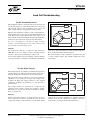
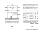
VPG TRANSDUCERS Load Cells Application Note VPG-08 Load Cell Troubleshooting Scope Load cells are designed to sense force or weight under a wide range of adverse conditions; they are not only the most essential part of an electronic weighing system, but also the most vulnerable. Load cells m ight be damaged because of (shock) overloading, lightning strikes or heavy electrical surges in general, chemical or moisture ingress, mishandling (dropping, lifting on cable, etc.), vibration or internal component malfunction. As a direct result the scale or system might (zero) drift, provide unstable/unreliable readings or not register at all. This application note is written to assist our customers with potential load cell problems. It describes basic field tests which can be performed on site, and provides the information necessary to interpret the results. Proper field evaluation is absolutely critical to prevent similarly induced damage in the future! Under no circumstances should fault location, as described below, be attempted on load cells installed in a hazardous area! In General Carefully check the system integrity before evaluating the load cells: Document Number: 11867 Revision 14-Dec-2011 The following test equipment is required to properly evaluate a load cell: • A high quality, calibrated, digital volt- and ohmmeter with a measuring accuracy of ±0.5Ω and ±0.1 mV, to measure the zero balance and integrity of the bridge circuit. • A megohm meter, capable of reading 5000 MΩ with an accuracy of 500 MΩ at 50 volts, to measure the insulation resistance. Do not use megohm meters which supply more than 50 volts to the load cell, in order to prevent permanent damage! • A means to lift the dead load (weighbridge, tank, hopper, conveyor, etc.) off the load cell to be able to measure the zero balance or to remove the load cell(s), i.e. a crane, hydraulic jack, etc. Load cells are produced according to specifications and tolerances which are described in the applicable data sheet. More detailed information can be found on the calibration certificate which is packed with each load cell. The calibration certificate mentions the exact values for the input and output resistance, insulation resistance, zero balance, rated output and the correct wiring code; it provides an important reference for the values which can be measured and should be f iled with the system documentation set. For technical support, contact in Americas [email protected], in Europe [email protected], in China [email protected], in Taiwan [email protected] www.vpgtransducers.com 1 A PPL I CAT I O N N OT E • Check for force shunts (might be caused by dirt, mechanical misalignment or accompanying components such as stay- or check rods). • Check for damage, corrosion or significant wear in the areas of load introduction. • Check cable connections to junction box and indicator. • Check the measuring device or indicator with an accurate load cell simulator. Visually inspect the load cells before performing the tests as described on the following pages. Pay particular attention to signs of corrosion (especially around the critical gauge area), the integrity of the cable (might be compromised due to cuts, abrasions, etc) and the condition of the cable entry. Test #1 Zero Balance Test #2 Insulation Resistance OK VPG-08 OK Te Br Inte VPG Transducers Wrong Wrong Load Cell Troubleshooting TEST PROCEDURES AND ANALYSIS Mechanical Moisture or chemical overload Test Procedures andfor Analysis The diagram below represents a proposed sequence testing load cells after a particular system ingress thea proposed fault location byfor moving relatively deadweight over each load cell, The malfunction. diagram below Isolate represents sequence testing a load cells aftersmall a particular system malfunction. Isolate the faultor location by moving a relatively small by disconnecting load cell by deadweight load cell. over each load cell, or by disconnecting load cell by load cell. R1kΣ Sudden change in Zero point Unstable readings, random change in Zero point Scale reads overload, incorrect or not at all Erratic readings when load is appliedcircuit or removed Short Brok or com to housing / screen Test #1 Zero Balance Test #2 Insulation Resistance OK OK Test #3 Bridge Integrity OK TEST #1: ZERO BALANCE Wrong Mechanical overload Test #4 Shock Resistance Electrica or in shor OK Wrong Wrong The Zero Balance is defined as the load Wrong cell output in a "no-lo deadload) has to beElectrical removed from the load cell. Low capacity load c Moisture overload Failed electrical or chemical or internal connection the ingress load cell is designed to measure force to prevent the weight of the short circuit The load cell should be connected to a stable power supply, preferab R≤1 kΩ R∞ R1kΣ R4 of at least 10 volts. Disconnect any other load cell for multiple load c Measure across Short circuit the voltage Broken wire the load cell's output leads with a milli to housing / screen or component excitation voltage to obtain the Zero Balance in mV/V. Compare the certificate ( if available ) or to the data sheet. Test #1: Zero Balance TEST #1: ZERO BALANCE A PPL I CAT I O N N OT E The Zero Balance is defined as the load cell output in Input The Zero BalanceTherefore, is defined all as weight the load(including cell output in a "no-load" situation. Therefore, all weight (including a "no-load" situation. deadload) has has to be removed from Lowcapacity load cells should be measured in the position in which deadload) to be removed fromthe theload load cell. Low ~ capacity cellsisshould be to measured thetoposition the load cell designed measure in force preventin the weight of the element giving wrong results. whichThe the load load cell cell should is designed to measure topower prevent be connected to aforce stable supply, preferably a load cell indicator with an excitation voltage the weight of the element giving wrong results. of at least 10 volts. Disconnect any other load cell for multiple load cell systems. Measure the voltage across the cell's output leads with a millivoltmeter and divide this value by the input or The load cell should be connected to aload stable power supply, excitation voltage to obtainwith the Zero Balance involtage mV/V. Compare the Zero balance to the original load cell calibration preferably a load cell indicator an excitation ( if available ) or toany the other data sheet. of at certificate least 10 volts. Disconnect load cell for Output multiple load cell systems. V Measure the voltage across the load cell's output leads Input with a millivoltmeter and divide this value by the input ~ or excitation voltage to obtain the Zero Balance in mV/V. Compare the Zero balance to the original load cell calibration certificate ( if available ) orANALYSIS to the data sheet. zero output changes per time period are most likely in the strain gauge resistance Changes in Zero undergoing Balancea change usually occur if the loadbecause cell has been Analysis Output of chemical or moisture intrusion. However, in this case excessive shocks.theLoad cells that experience progressive zero ou insulation resistance and/or the bridge integrity will Changes in Zero Balance usually occur if the load cell also be has been permanently deformed by overloading and/or undergoing a change incompromised. the strain gauge resistance because of chem excessive shocks. Load cells that experience progressive the insulation resistance and/or the bridge integrity will also be comp ANALYSIS V Changes in Zero Balance usually occur if the load cell has been permanently deformed by overloading and/or For technical support, contact in Americas www.vpgtransducers.com Document Number: 11867 excessive shocks. Load cells that experience progressive zero [email protected], output changes per time period are most likely in Europe [email protected], in China [email protected], 2 Revision undergoing a change in the strain gauge resistance because of chemical or moisture intrusion. However, in14-Dec-2011 this case in Taiwan [email protected] the insulation resistance and/or the bridge integrity will also be compromised. body. Repeat the measurement between the same 4 or 6 leads and the resistance between the load cell body and cable shield. Never use a megohmmeter to measure the input or output resistance, TEST #2: INSULATION RESISTANCE exceeds the maximum excitation voltage by far! VPG-08 The insulation resistance is measured between the load cell circuit a VPG Transducers cell from the junction box or indicator and connect all input, output a Input Measure the insulation resistance with a megohmmeter between the the measurement between the same 4 or 6 leads and Load body. Cell Repeat Troubleshooting resistance between the load cell body and cable shield. Never use a megohmmeter to measure the input or output resistan Outputvoltage by far! Test #2: Insulation Resistance exceeds the maximum excitation Σ The insulation resistance is measured between the load cell circuit and element or cable shield. Disconnect the load cell from the junction box or indicator and connect all input, output and sense (if applicable) leads together. Input ANALYSIS Measure the insulation resistance with a megohmmeter between these four or six connected leads and the load cell The insulation resistance of all load cells should be 5000 MΩΩ or more fo body. Repeat the measurement between the same 4 or 6 cable screen and housing to cable screen. leads and the cable shield. Finally measure the insulation Output A lower value indicates electrical leakage, which is usually caused by mo resistance between the load cell body and cable shield. Σ the load cell or cable. Extremely low values (≤ 1k ΩΩ ) indicate a short cir results usually in unstable load cell or scale reading ou Never use a megohmmeter to measure the input or output Electrical leakage resistance, as it normally operates at a voltage which exceeds temperature. the maximum excitation voltage by far! Analysis ANALYSIS load cell or cable. low values (≤1kbeΩ 5000 ) indicate The insulation resistance of all load cells should be The insulation resistance of Extremely all load cells should MΩΩa or mor short circuit rather than moisture ingress. 5000 MΩ or more for bridge circuit to housing, bridge cable screen and housing to cable screen. circuit to cable screen and housing to cable screen. TEST BRIDGE INTEGRITY Electrical leakage results usually which in unstable load cell A lower#3: value indicates electrical leakage, is usually caused b or scale reading output. The stability might vary with A lower value indicates electrical leakage, which is usually the load cell or cable. Extremely low values (≤ 1k ΩΩ ) indicate a shor bridge is verified by measuring the input and output resistan temperature. caused by moisture or chemical contaminations The within the integrity Test #3: Bridge Integrity Electrical leakage usually in unstable cell or scale readin Disconnect the load results cell from the junction box orload measuring device. The input and output resistance is measured with an ohmmeter across eac temperature. the input and output resistance to the original calibration certificate (if av The bridge balance is obtained by comparing the resistance from -output difference between both values should be smaller than, or equal to 1 ΩΩ. The bridge integrity is verified by measuring the input and TEST #3: output resistance as well as the bridge balance. Disconnect the load cell from the junction box or measuring device. BRIDGE INTEGRITY Input Σ resistance from -output to -input, and -output to +input. The difference between both values should be smaller than, or equal to 1Ω. Analysis Input Σ A PPL I CAT I O N N OT E The bridge integrity is verified by measuring the input and output res The input and output resistance is measured with an Disconnect the load cell from the junction box or measuring device. ohmmeter across each pair of input and output leads. Σ input and output resistance is measured with an ohmmeter acros Compare the input and output resistance to theThe original calibration certificate (if available) or to the data sheet and output resistance to the original calibration certificate ( the input specifications. The bridge balance is obtained by comparing the resistance from -ou Output Σ The bridge balance is obtained by comparing the between both values difference should be smaller than, or equal to 1 ANALYSIS result from over-voltage (lightning or welding), physical Changes in bridge resistance or bridge balance are most resistance or bridge balance most excessive often caused by damage from shock, vibration or are fatigue, often caused by a broken or burned wire, anChanges electrical in bridge temperature, or from production inconsistencies. component failure or internal short circuit. This might failure component or internal short circuit. This might result fromΣover-v damage from shock, vibration or fatigue, excessive temperature, or from Output Document Number: 11867 Revision 14-Dec-2011 For technical support, contact in Americas [email protected], in Europe [email protected], in China [email protected], inANALYSIS Taiwan [email protected] Σ www.vpgtransducers.com 3 TEST #4: SHOCK RESISTANCE VPG-08 VPG Transducers The load cell should be connected to a stable power supply, preferabl of at least 10 volts. Disconnect all other load cells for multiple load ce With a voltmeter connected to the output leads, lightly rap on the load Load Cell Troubleshooting Exercise extreme care not to overload low capacity load cells while te Watch the readings during the test. The readings should not become e return to original zero readings. Test #4: Shock Resistance The load cell should be connected to a stable power supply, preferably a load cell indicator with an excitation voltage of at least 10 volts. Disconnect all other load cells for multiple load cell systems. With a voltmeter connected to the output leads, lightly rap on the load cell with a small mallet to mildly shock it. Exercise extreme care not to overload low capacity load cells while testing their shock resistance. Input ~ Output Watch the readings during the test. The readings should not become erratic, should remain reasonably stable and return to original zero readings. Analysis V ANALYSIS Erratic readings may indicate a failed electrical connection Erratic readings may indicate a failed electrical or a damaged glue layer between strain gauge and element element as a result of an electrical transient. as a result of an electrical transient. connection or a dama LOAD CELL EVALUATION FORM Load Cell Evaluation Form The following load cell evaluation form should be used as a guide for the testing and evaluation of load cells. We recommend that this form be included in the customer dossier and used as the basis to discuss the test results and diagnostics with third parties. A PPL I CAT I O N N OT E A load cell evaluation form is included in this application testing and cells. We recommend this If a load cell is returned to VPG Transducers, thefor Evaluation Form will evaluating assist our repair load department in further diagnostics and repair of the cell. and its use as a basis to discuss the test results and diagnost If a load cell is returned to Vishay Revere Transducers, th department in further diagnostics and repairing the cell. Customer support: The Vishay Revere Transducers combines sixty years of lo application know how. For further information, please con one of our regional sales offices. www.vpgtransducers.com 4 For technical support, contact in Americas [email protected], in Europe [email protected], in China [email protected], in Taiwan [email protected] Vishay Revere Transducers B.V. Document Number: 11867 Revision 14-Dec-2011 VPG-08 VPG Transducers Load Cell Troubleshooting Load Cell Evaluation Form Company:________________________________________________ Contact person:___________________________________ Address:___________________________________________________ City / Country:___________________________________ Tel. / Fax.:__________________________________________________ Repair order:__________ Date:____________________ Load cell type:______________________________________________ Serial number:___________________________________ Capacity:_________________________________________________ Accuracy grade:___________________________________ Short description of system failure and application:______________________________________________________________ __________________________________________________________________________________________________________ __________________________________________________________________________________________________________ __________________________________________________________________________________________________________ Visual Inspection Label ❒OK ❒Unreadable ❒ Missing Condition ❒ Like new ❒ Broken welds ❒ Cable cut ❒ Visual mechanical overload ❒ J-box damage ❒ Dents/cracks in parts Corroded parts ❒Weld(s) ❒Housing/element ❒ J-box/cable entry ❒ Top/bottom plate ❒Diaphragm ❒Bellow/tube/cubs Affected by chemicals ❒No ❒Unknown ❒ Yes: _______________ Electrical Inspection Bridge Measurements Actual Specification Zero balance mV/V ≤±1% of rated span ❒OK Conclusion ❒Wrong Input resistance Ω Ω±1% ❒OK ❒Wrong Output resistance Ω Ω±1% ❒OK ❒Wrong Output – to input – Ω ❒OK ❒Wrong Out put – to input + Ω difference ≤±1% ❒OK ❒Wrong Insulation Resistance Actual Specification Bridge to housing MΩ ≥5000 MΩ ❒OK ❒Wrong Bridge to shield MΩ ≥5000 MΩ ❒OK ❒Wrong Shield to housing MΩ ≥5000 MΩ ❒OK ❒Wrong Conclusion ❒Moisture ingress ❒ Short circuit ❒ Broken wire/component ❒ Excessive heat ❒Electrical transients ❒ Mechanical overload ❒ Excessive corrosion ❒ Broken cable ❒ Other: ____________________________________________ Recommendation ❒ ❒ ❒ ❒ Return load cell to supplier for further evaluation and repair (if possible) Return load cell to supplier for warranty Load cell beyond (economic) repair ________________________________________________________________________________ Document Number: 11867 Revision 14-Dec-2011 For technical support, contact in Americas [email protected], in Europe [email protected], in China [email protected], in Taiwan [email protected] www.vpgtransducers.com 5 A PPL I CAT I O N N OT E Expected Reason for Failure