1
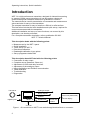
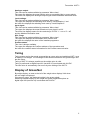
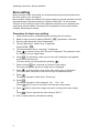
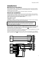
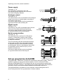
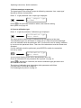
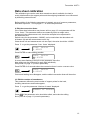
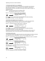
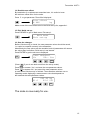
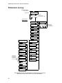
GB
Transmitter
WST 3
From prog. name W001A100
Operating instructions,
Quick installation
Transmitter WST 3
Contents
Introduction
....................................................................... 2
Operating instruction
General ..........................................................
Power supply .................................................
Start-up ..........................................................
Views in Operating mode ...............................
Taring .............................................................
Display of Gross/Net ......................................
Zero setting ....................................................
3
3
3
4
5
5
6
Installation
Mechanical installation ................................... 7
Electrical installation ....................................... 7
Set-up programme deltaCOM ........................ 8
Quick set-up, calibration
General .......................................................... 9
Common parameters ..................................... 9
Data sheet calibration .................................. 13
Dead weight calibration ................................ 16
Parameter survey
...................................................................... 20
Quick set-up list
................................................................ App. 1
1
Operating instructions, Quick installation
Introduction
WST 3 is a high performance transmitter, designed for industrial measuring
by means of strain gauge transducers. It can be used as a slave unit,
communicating with a network master/PLC by Modbus or Profibus.
The network can be used for transmission of commands and measurement
values and also for set-up of the transmitter.
The compact transmitter is easy to install on a DIN rail or a flat surface.
This instruction includes the basic installation and quick set-up, required for
correct measurement with the transmitter.
Additional installation and set-up of more functions, not covered by this
description, can also be performed.
For a complete transmitter description, refer to publication 600 630:
WST 3 Technical Manual
This description deals with the following points:
• Measurement by the WST 3 panel.
• Quick installation.
• ‘Quick set-up’ for WST 3.
• Data sheet calibration.
• Deadweight calibration in two points.
• Set-up programme deltaCOM.
This description does NOT deal with the following points:
• Connection of relay output.
• Complete set-up (password, filters etc.).
• Adjustment of levels and relay functions.
• Adjustment of the analogue output.
• Using the Modbus and Profibus communication.
• Table calibration.
• Troubleshooting.
• Diagnostics.
Transducer
Analogue output
Relay outputs
Modbus
Digital inputs
WST 3
Profibus-DP
Control unit,
Profibus
Control unit (deltaCOM)
or
External display
24 V DC
Figure 1. All connections to WST 3 are made through terminal block or connector.
2
Transmitter WST 3
Operating instructions
General
This section describes the display and the function key operation when WST 3
is in normal Operating mode.
Power supply
Power supply to the transmitter should not be turned off during week-ends and overnight. Continuous power supply to electronics and transducers prevents moisture
condensation in the units.
Start-up
As soon as power is connected to the transmitter, start-up is performed.
The text ‘WST 3’, the programme name and the serial number of the transmitter
are displayed for about five seconds.
Then WST 3 is automatically switched over into Operating mode.
(If the transmitter is set for operator start-up, the text
‘Press ENTER to start WST’ is displayed until the function key
to the right is pressed and the transmitter enters Operating mode.)
If an error occurs the start-up halts and an error message is displayed.
Error codes and error corrections are described in the Technical Manual for WST 3,
section 8, Troubleshooting.
As WST 3 enters in Operating mode, the first view is a standard view. It contains
the measurement value, status of the used relays (R1:/R2: '1' = on or '0' = off) and
at the lower right corner an area with information about the Modbus communication.
In this area 'EXT' means serial communication to an external display. An 'address'
means that the transmitter is set for Modbus communication with a master unit, and
the address flashes as a message to the transmitter is received. If the area is empty
this means that the serial communication is not in use.
Figure 2. Front view of WST 3 in Operating mode. A weight value and
information about relay status and Modbus address is displayed.
3
Operating instructions, Quick installation
Views in Operating mode
As WST 3 is in Operating mode the views Weight value and Profibus status are
always available. The remaining views can be set On or Off by parameters under
'Main menu General'.
Function keys
and
by swiftly pressing
are used for selection among the available views and
WST 3 can always be switched to the Weight value view.
From any view, WST 3 switches to Quick set-up mode as the function key
is pressed for 2 seconds.
Weight value, normal view.
This view is always available. It is the first view displayed after start-up, reset or
set-up mode.
The upper line displays the actual weight value as net weight (Net) or gross weight.
The lower line displays status for the used relays, R1:/R2: '1' = on or '0' = off,
and an area for the Modbus address or information about the serial communication.
Zero setting.
This view is made available by parameter 'Zero function'. It displays the actual weight
value as net weight (Net) or gross weight.
As gross weight is displayed it can be set to zero by the ENTER-key
.
By zero setting of the gross weight, the actual tare value is also set to zero.
Start up/Reset
Weight value
Always On
Net
R1:1
123.4 kg
R2:1 001
Zero setting
Net
123.4 kg
Zero
Analogue output signal
Net
123.4 kg
5.430 V
001
Level settings
L1
L2
Set On/Off in Zero function
Set On/Off in More views
Set On/Off in More views
Input signal
Set On/Off in More views
99999.9 kg
0.0 kg
0.18200mV/V
R1:1
R2:1 001
S/N:, Progr.
S/N:
Progr.
Profibus status
Profibus-DP
Online
Set On/Off in More views
Always On
XX-XXXX
XXXXXXXX
010
Figure 3. WST 3 in Operating mode can always display Weight value and Profibus status.
Depending on the setting, alternative views can also be displayed.
4
Transmitter WST 3
Analogue output.
This view can be made available by parameter 'More views'.
The upper line displays the actual weight value as net weight (Net) or gross weight.
The lower line displays the analogue output signal and the Modbus information area.
Level settings.
This view can be made available by parameter 'More views'.
The upper line displays the switching level used by 'Level/Setpoint 1' and
the lower line displays the switching level used by 'Level/Setpoint 2'.
Input signal.
This view can be made available by parameter 'More views'.
The upper line displays the actual transducer input signal in mV/V.
The lower line displays status for the used relays, R1:/R2: '1' = on or '0' = off,
and the Modbus information area.
S/N:, Progr.
This view can be made available by parameter 'More views'.
The upper line displays the transmitter serial number and
the lower line displays the name of the installed programme.
Profibus status.
This view is always available.
The upper line displays the Profibus address of the transmitter and
the lower line contains status information for the Profibus communication.
Taring
Taring means storing the actual gross weight as a tare value and switching WST 3 over
to display of net weight. The net weight is the difference between the gross weight and
the tare value.
Taring of WST 3 is always possible as the weight value is valid.
Taring is performed as digital input IN1 (terminal 15) is activated with 24 VDC.
The tare value is automatically set to zero by zero setting of the WST 3.
Display of Gross/Net
By weight display, an area to the left of the weight value displays 'Net' when
the net weight is displayed.
If the area is empty, the displayed weight is the gross weight.
Switching between display of net weight and gross weight takes place as
digital input IN2 (terminal 16) is activated with 24 VDC.
5
Operating instructions, Quick installation
Zero setting
Minor correction of the zero setting can be performed during normal operation from
the ‘Zero setting’ view, see page 4.
But to perform a basic zero setting of the gross weight, the normal operation must be
interrupted and the following sequence carried out with WST 3 in set-up mode.
This type of zero setting is a part of the calibration sequences, but a separate zero
setting may also be needed, for example if the equipment on the scale has been
changed, influencing the weight.
Procedure for basic zero setting
1.
Check that the scale is unloaded before performing the zero setting.
2.
3.
4.
Switch to set-up mode by holding ESCAPE (
Enter the valid password, if this is demanded.
The text ‘Main menu Quick set-up’ is displayed.
5.
).
Press ENTER (
The first parameter name, ‘Language’, is displayed.
) pressed for 2 seconds.
a number of times until ‘Set zero’ is displayed. The parameter value
Press
for ‘Set zero’ is a live weight value.
6.
Press
. The parameter value is set to zero and a flashing cursor appears
to the left on the lower line.
(The zero setting can be cancelled by pressing
)
7.
Press and hold
for 2 seconds to confirm the new setting.
The cursor disappears and a live weight value is displayed.
8.
Press
, read and make a note of the ‘Zero offset’ value in Appendix 1.
(The ‘Zero offset’ value can be used for set-up of a replacement unit.)
9.
Press
.
The display changes to ‘Main menu Exit set-up.’
10. Press
.
The display changes to ‘Save changes? No
(Press
11. Press
or
Esc. Yes’.
(Esc.) if you do not wish to exit from the set-up mode.)
(No) to cancel the change and return to the previous zero setting,
Press
(Yes) to save the new zero setting in WST 3.
12. WST 3 restarts with the selected zero setting.
6
Transmitter WST 3
Installation
Mechanical installation
Each transmitter WST 3 contains several circuit boards, built into a protective plastic
housing which can be snap-mounted on a 35 mm wide DIN rail, or mounted on a flat
surface by two 4 mm screws.
The transmitter should have at least 10 mm free space on each side.
Electrical installation
For the electrical connections to the connector and terminal blocks of the transmitter
shielded cables are needed, except for the power supply. All cables should be routed
so that electromagnetic interference from power cables is avoided.
Cable connection is shown in the diagrams below.
Transducer input
Terminals 1 – 7 (8).
Transducer connection should be handled with great care to achieve best measuring
data. Integrated transducer cables may not be shortened.
NOTE!
Transducer cables must be routed at least 200 mm away from 230/380 V,
50/60 Hz power cables. By cables with other frequencies or high power,
an even wider distance is preferable.
4-wire connection should be used if the integrated transducer cable can be connected
directly at WST 3. By 4-wire connection, excitation and sense must be interconnected
at the transmitter, see diagram below. The cable shield and terminal 5 should be
connected to earth via the mounting rail.
6-wire connection should be used if the integrated cable must be lengthened or if several
transducers should be connected to the transmitter.
Connect the cable shield and terminal 5 to earth via the mounting rail. In the diagram
below connections are shown for the junction box SL-4 from Nobel Weighing Systems.
4-wire connection
Excitation +
Excitation -
Signal +
Signal -
Transducer
J11
J12
Exc.+
Sign.Exc.Sign.+
J21
J22
Transducer
Transducer
J102
J103
J104
J106
J23
J24
J2
J108
J105
J58
Exc.+
Sign.Exc.Sign.+
Transducer
J101
J13
J14
J1
J31
J32
J59
R CAL
EXC+
SENSE+
EXC–
SENSE–
SHIELD
SIGN.+
SIGN.–
CAL
1
2
3
4
5
6
7
8
EXC+
SENSE+
EXC–
SENSE–
SHIELD
SIGN.+
SIGN.–
CAL
6-wire connection
Junction box SL-4
Exc.+
Sign.Exc.Sign.+
1
2
3
4
5
6
7
8
J107
J10
J33
J34
J3
J41
J42
J43
J44
J4
7
Operating instructions, Quick installation
Power supply
Terminals 17, 18.
The transmitter is powered by 24 V DC.
Rail mounted power supplies can be ordered
from Nobel Weighing Systems.
+24 V DC
0 V (24)
17
18
+
24
25
OUT+
OUT–
- 24V
Analogue output
Terminals 24, 25.
The measurement value is presented at the analogue
output as a current or voltage signal, according to
the choice in the set-up.
Connect the cable shield to ground, preferably to
a ground terminal at the mounting rail.
+
Digital inputs
Terminal 15, 16.
Connection of +24 VDC to the digital inputs causes
Taring and Gross/Net switching respectively.
Connect the cable shield to ground, preferably
to a ground terminal on the mounting rail.
24 V
+
terminal 18
Taring
Gross/Net
15
16
IN1
IN2
19
20
21
22
23
TXD–
TXD+
RXD–
RXD+
COM.
Serial communication
Terminals 19 – 23.
The transmitter has a serial port for RS-485 on
2-wires or 4-wires with common earth (COM).
If necessary, a converter unit can be connected
to adapt the interfaces.
The line must have 120 ohm terminating resistors
at both ends. At WST 3 they should be mounted
on separate terminals and connected according
to the diagrams. Refer to manufacturer instructions
for termination at the control unit (PC), or at a
possible converter unit.
Connect the cable shield to ground, preferably
to a ground terminal at the mounting rail.
Set-up programme deltaCOM
2-wire
*
120Ω
* Terminating resistor on separate
terminals at the last unit on the line.
4-wire
*
120Ω
*
120Ω
19
20
21
22
23
* Terminating resistor on separate
terminals at the last unit on the line.
Transmitter WST 3 should be connected to transducer(s) and power supply. Then it is
possible to perform a set-up from the front panel or from a connected PC with
Windows 95/98/2000/XP/NT4.0. A diskette with the set-up programme deltaCOM is
included in the WST 3 delivery. This diskette also contains instructions for connection
and set-up of the serial communication between the transmitter and the PC.
Through deltaCOM it is possible to find all modules communicating with the PC,
and to study and edit all set-up parameters for these modules.
8
TXD–
TXD+
RXD–
RXD+
COM.
Transmitter WST 3
Quick set-up, calibration
General
Set-up of all parameters in WST 3 can be performed from the control unit by serial
communication, using the programme deltaCOM. Set-up can also be performed from
the transmitter front panel, for example the ‘Quick set-up’ of certain parameters
described in this section.
Calibration is essential to get correct measurement results.
Two calibration methods are available in the ‘Quick set-up’:
Data sheet calibration, for calibration when transducer data are available and
the installation is free from disturbing mechanical forces.
Dead weight calibration, normally the most accurate calibration method,
where known weights are used to give well defined loads on the scale.
Before selection of calibration method, the value of some common parameters must
be set.
All parameter values from the calibration should be noted in the set-up list, see
Appendix 1. These values are useful later, if the transmitter must be replaced.
Common parameters
These parameters define: the language, measurement unit and resolution used by
the transmitter, and also the capacity and signal type for the analogue output.
Set-up
1. Access ‘Quick set-up’
At normal operation WST 3 displays the actual weight value. Status for the internal
relays (R1/R2) in use and the transmitter Modbus address are also displayed.
R1:1
123.4 kg
R2:1 001
Press and hold the ESCAPE key for 2 seconds.
2 seconds
Main menu
Quick set-up
This switches the transmitter into Set-up mode, displaying the main menu
for ‘Quick set-up’.
As WST 3 is in Set-up mode, normal measuring functions are interrupted!
9
Operating instructions, Quick installation
2. Showing the parameters.
Press ENTER.
Language
English
The first parameter in ‘Quick set-up’ will be displayed.
3. Edit the language (a choice parameter).
‘Language’ is a choice parameter with a number of alternatives available.
Press ENTER to make editing possible.
Language
English
A cursor starts flashing to the left on the parameter value line.
Press + to step forwards to next alternative, or press – to step backwards
to the previous alternative, until the correct alternative is displayed.
Language
(alternatives)
Press ENTER for 2 seconds to accept the displayed alternative.
2 seconds
Language
English
The cursor disappears and the displayed alternative is activated.
4. Edit the measurement unit for the transmitter.
By this parameter, the measurement unit for the measurement value is defined.
Press + to get parameter ‘Measurement unit’ displayed.
Measurement unit
kg
Press
if the measurement unit should be edited,
and edit the value like in point 3. above.
10
Transmitter WST 3
5. Edit the transmitter resolution.
With this parameter, the number of decimals and the resolution of the last digit
of the measurement value are defined.
This parameter influences all measurement values using the measurement unit.
Press
+
to get parameter ‘Resolution’ displayed.
Resolution
0.1
kg
Press
if the resolution should be edited, and make the editing
like in point 3. on page 10.
In the following examples, resolution with two decimals is used.
6. Edit the transmitter capacity (numeric parameter).
This parameter defines the capacity of the transmitter, i.e. the weight value that
corresponds to full range at the analogue output.
Press
+
to get the parameter ‘Capacity’ displayed.
Capacity
500.00
kg
Press ENTER to make editing possible.
Capacity
0500.00
kg
A cursor starts flashing to the left on the parameter value line, indicating which digit
that can be edited.
Press ENTER to move the cursor, step by step to the right in the parameter value, to
the digit to edit.
Capacity
0500.00
Press
+
(or
–
(repeated)
kg
) until the wanted digit value is displayed (1 in this example).
Capacity
0100.00
kg
When necessary, press ENTER again to move the cursor to another digit to edit.
Press ENTER for 2 seconds when the capacity parameter value is correct.
2 seconds
Capacity
100.00
kg
The cursor disappears, and the edited parameter value becomes active.
11
Operating instructions, Quick installation
7. Edit the analogue output type.
The signal type for the analogue output is defined by parameter ‘Ana. output type’
that has a number of alternatives.
Press
+
to get parameter ‘Ana. output type’ displayed.
Ana. output type
4-20mA
Press
if the parameter should be edited, and make the editing
like in point 3. on page 10.
8. Chose a calibration type.
Press
+
to get the parameter ‘Calibration type’ displayed.
Calibration type
Data sheet
The value points out which type of calibration that was performed last time.
Two calibration types can be chosen in ‘Quick set-up’: Data sheet and Deadweight.
As a new calibration shall be performed, WST 3 must first be set for editing, indicated
by a cursor at the parameter value. Then one of the alternatives must be chosen and
accepted.
If a new calibration shall be performed, press ENTER to switch the transmitter
into set-up mode.
Calibration type
Data sheet
A cursor starts flashing to the left on the parameter value line.
Chose an alternative for the parameter like in point 3. on page 10.
is pressed for 2 seconds, the chosen calibration type gets active and
When
the calibration can start.
The choice of calibration type determines which parameters will follow:
For Data sheet, se point 9. on page 13.
For Deadweight, se point 9. on page 16.
12
Transmitter WST 3
Data sheet calibration
This calibration type can be used when transducer data is available, the load is
evenly distributed on the support points and the weighing installation is not influenced
by disturbing external forces.
Before editing of the following parameters is started, set-up of common parameters,
described in points 1. – 8. on pages 9 – 12 should be performed.
9. Edit the conversion factor.
If the ‘Data sheet’ alternative was chosen at 8. on page 12, next parameter will be
‘Conv. factor’. This parameter defines a constant by which a weight value,
expressed in the measurement unit, should be multiplied to be expressed in
the data sheet unit.
Default value for the parameter, 9.80665, can be used when the data sheet unit
is Newton (N) and the measurement unit is ‘kg’.
If data sheet unit and measurement unit are equal, the value should be 1.00000.
Press
+
to get the parameter ‘Conv. factor’ displayed.
Conv. factor
9.80665
Press ENTER to make editing possible.
Conv. factor
09.80665
A cursor starts flashing to the left on the parameter value line.
Now editing can be performed for each digit individually.
See point 6. on page 11 (numeric parameter).
Press ENTER for 2 seconds when the conversion factor is set to a correct value.
2 seconds
Conv. factor
9.80665
Cursor and leading zeros disappear, and the edited conversion factor will be active.
10. Edit the number of transducers.
This parameter defines the total number of support points for the load,
including transducers and fixed supports.
Press
+
to get the parameter ‘Number of transd’ displayed.
Number of transd
3
Press
if the parameter value should be edited, and make the editing
like in point 6. on page 11 (numeric parameter).
13
Operating instructions, Quick installation
11. Set the rated load for one transducer.
It is assumed that all transducers connected to the transmitter have the same
rated load and impedance. The rated load for one transducer, expressed in
the data sheet unit used to calculate the conversion factor (see 9. on page 13),
should be entered.
NOTE! If the data sheet value is for instance 5 kN,
this parameter should be set to 5 000 (N).
Press
+
to get the parameter ‘Rated load’ displayed.
Rated load
2000.0
Press
if the parameter value should be edited, and make the editing
like in point 6. on page 11 (numeric parameter).
12. Set the rated output for the transducers.
Rated output for each transducer, a value in mV/V, is given in the data sheet.
For fixed support points the rated output should be set to ”0.00000”.
Press
+
to get the parameter ‘Rated output 1’ displayed.
Rated output 1
2.03900
mV/V
Press
if the parameter value should be edited, and make the editing
like in point 6. on page 11 (numeric parameter).
Parameters will follow for the number of support points given at 10. on page 13.
Set the parameter value to the rated output for each transducer/fixed support.
13. Set the scale to zero.
This parameter displays the weight value with the actual settings (but with one decimal
more than what is set in ‘Resolution’). Use it to set the weight value to ‘zero’.
Press
+
to get parameter ‘Set zero’ displayed, and check that the scale is unloaded.
Set zero
XXXX.XXX
kg
Press ENTER to set the parameter value to zero.
Set zero
+0000.00
kg
The value is set to zero with leading sign and a flashing cursor.
Press ENTER for 2 seconds.
2 seconds
Set zero
0000.000
kg
The cursor disappears and the zero setting is accepted.
14
Transmitter WST 3
14. Read the zero offset.
By installation of a replacement transmitter later, it is useful to know
the total zero offset value for the scale.
Press
+
to get parameter ‘Zero offset’ displayed.
Zero offset
X.XXX
kg
Make a note of the zero offset value in the Quick set-up list, appendix 1.
15. Exit ‘Quick set-up’.
Press ESCAPE to get to ‘Main menu Exit set-up’.
Main menu
Exit set-up
16. Save the changes.
Before ‘Quick set-up’ is closed, the new parameter values should be saved,
i.e. copied to a specific memory in the transmitter.
Alternatively the new values can be cancelled, and all parameters will resume
the values they had before ‘Quick set-up’ was started.
Press ENTER to get the sub menu displayed.
Save changes?
No
Esc. Yes
(Press
Press
if you do not wish to exit from the set-up mode.)
to answer ‘Yes’, and save the new parameter values.
Press
to answer ‘No’, and cancel the new parameter values.
In both cases ‘Quick set-up’ is finished. The transmitter switches over to
Operating mode, displaying a measurement value that depends on
the load and the valid parameter values.
R1:1
000.00 kg
R2:1 001
The scale is now ready for use.
15
Operating instructions, Quick installation
Dead weight calibration
This is the most accurate calibration type. It requires that known weights
to at least two-thirds of the scale capacity are available.
Below, a dead weight calibration in two points is described.
Before editing of these parameters is started, set-up of common parameters,
described in point 1. – 8. on pages 9 – 12 should be performed.
9. Set the value for calibration point 1.
If the ‘Deadweight’ alternative was chosen at 8. on page 12, next parameter
will be ‘Value cal. p.1’. This parameter defines the known load on the scale for
the lower calibration point.
Press
+
to get the parameter ‘Value cal. p.1’ displayed.
Value cal. p.1
X.XX
kg
The displayed parameter value is the load on the scale that was set for the lower
calibration point in the last calibration, normally zero (= unloaded scale).
Press ENTER.
Value cal. p.1
XXXX.XXX
kg
Actual measurement value for the scale is displayed (as a ‘live’ weight value)
with a cursor and one decimal more than what is set in parameter ‘Resolution’.
Check the load on the scale (normally unloaded).
Press ENTER again to make editing possible.
Value cal. p.1
+0000.00
kg
The displayed parameter value is the value for the lower calibration point from
the last calibration, with leading sign and a cursor.
The parameter value can be edited, according to point 6. on page 11 (numerical
parameter), to correspond to the actual load on the scale, normally zero.
Press ENTER for 2 seconds.
2 seconds
Value cal. p.1
X.XX
kg
This finishes the editing and the load that is set for the lower calibration point
is displayed without cursor.
16
Transmitter WST 3
10. Set the value for calibration point 2.
This parameter defines the known load on the scale for the higher calibration point.
Press
+
to get the parameter ‘Value cal. p.2’ displayed.
Value cal. p.2
500.00
kg
The displayed parameter value is the load on the scale that was set for
the higher calibration point in the last calibration.
Press ENTER.
Value cal. p.2
XXXX.XXX
kg
Actual measurement value for the scale is displayed (as a ‘live’ weight value)
with a cursor and one decimal more than what is set in parameter ‘Resolution’.
Load the scale with known weights to at least two thirds of the scale capacity.
Press ENTER again to make editing possible.
Value cal. p.2
+0500.00
kg
The displayed parameter value is the value for the higher calibration point from
the last calibration with leading sign and a cursor.
The parameter value can be edited, according to point 6. on page 11 (numerical
parameter), to correspond to the actual load of known weights on the scale.
Press ENTER for 2 seconds.
2 seconds
Value cal. p.2
XXX.XX
kg
Editing is finished and the load that is set for the higher calibration point is displayed
without cursor.
11. Read the transducer signal for calibration point 1 (read only).
By possible installation of a replacement unit later, it is useful to know the values
of the transducer signal for the two calibration points.
Press
+
to get parameter ‘Transd.sign. p.1’ displayed.
Transd.sign. p.1
X.XXXXX
mV/V
Make a note of the parameter value in the Quick set-up list, appendix 1.
17
Operating instructions, Quick installation
12. Read the transducer signal for calibration point 2 (read only).
Press
+
to get parameter ‘Transd.sign. p.2’ displayed.
Transd.sign. p.2
X.XXXXX
mV/V
Make a note of the parameter value in the Quick set-up list, appendix 1.
13. Set the scale to zero.
This parameter displays the weight value with actual settings (but with one decimal
more than what is set in ‘Resolution’). Use it to set the weight value to ‘zero’ for
the unloaded scale.
Press
+
to get parameter ‘Set zero’ displayed, and check that the scale is unloaded.
Set zero
XXXX.XXX
kg
Press ENTER to set the parameter value to zero.
Set zero
+0000.00
kg
The value is set to zero with leading sign and a flashing cursor.
Press ENTER for 2 seconds.
2 seconds
Set zero
0000.000
kg
The cursor disappears and the zero setting is accepted.
14. Read the zero offset.
By possible installation of a replacement unit later, it is useful to know
the total zero offset value for the scale.
Press
+
to get parameter ‘Zero offset’ displayed.
Zero offset
X.XXX
kg
Make a note of the zero offset value in the Quick set-up list, appendix 1.
18
Transmitter WST 3
15. Exit ‘Quick set-up’.
Press ESCAPE to get to ‘Main menu Exit set-up’.
Main menu
Exit set-up
16. Save the changes.
Before ‘Quick set-up’ is closed, the new parameter values should be saved,
i.e. copied to a specific memory in the transmitter.
Alternatively the new values can be cancelled, and all parameters will resume
the values they had before ‘Quick set-up’ was started.
Press ENTER to get the sub menu displayed.
Save changes?
No
Esc. Yes
(Press
Press
if you do not wish to exit from the set-up mode.)
to answer ‘Yes’, and save the new parameter values.
Press
to answer ‘No’, and cancel the new parameter values.
In both cases ‘Quick set-up’ is finished. The transmitter switches over
to Operating mode, displaying a measurement value that depends on
the load and the valid parameter values.
R1:1
000.00 kg
R2:1 001
The scale is now ready for use.
19
Operating instructions, Quick installation
Parameter survey
Operating mode
Start up/Reset
Weight value
R1:1
123.4 kg
R2:1 001
for 2 seconds
Enter password:
(Wrong)(Correct)
Shown only if
'Security lock' is On.
Set-up mode,
Quick set-up
Main menu
Quick set-up
Language
English
Main menu
Exit set-up
Save changes?
No
Esc. Yes
Measurement unit
kg
Resolution
0.1
kg
Capacity
500.0
kg
Ana.output type
4-20mA
Calibration type
Data sheet
Shown for
the entered
number of
transducers.
Calibration type
Dead weight
Conv. factor
9.80665
Value cal. p.1
0.0
kg
Number of transd
3
Value cal. p.2
500.0
kg
Rated load
2000.0
Transd.sign. p.1
0.00000
mV/V
Rated output 1
2.03900
mV/V
Transd.sign. p.2
1.66631
mV/V
Rated output 2
2.03900
mV/V
Set zero
00123.40
Rated output 3
2.03900
mV/V
Zero offset
0.00
kg
kg
Rated output 4
2.03900
mV/V
Set zero
00123.40
kg
Zero offset
0.00
kg
The diagram shows the parameters in ‘Quick set-up’ and how
the function keys are used to view the parameters.
20
Shown only if
any changes
have been done.
Transmitter WST 3
Quick set-up list for WST 3
Address: ...........
Location/Notes: ..............................................................................................................
Programme name: .............................. Ser. no.: ........................ Date: ....................
Parameter
name
Language
Measurement unit
Resolution
Capacity
Ana. output type
Calibration type
Conv. factor
Number of transd
Rated load
Rated output 1
Rated output 2
Rated output 3
Rated output 4
Value cal. p.1
Value cal. p.2
Transd.sign. p.1
Transd.sign. p.2
Zero offset
Default
value
English
kg
0.1
500.0
4–20mA
Data sheet
9.80665
3
2000.0
2.03900
2.03900
2.03900
2.03900
0.0
500.0
0.00000
1.66631
0.00
Set-up
value
...........................
...........................
...........................
...........................
...........................
...........................
...........................
...........................
...........................
...........................
...........................
...........................
...........................
...........................
...........................
...........................
...........................
...........................
...........................
...........................
...........................
...........................
...........................
...........................
...........................
...........................
...........................
...........................
...........................
...........................
...........................
...........................
...........................
...........................
...........................
...........................
Appendix 1
Quick set-up list.
Operating instructions, Quick installation
Document no. 35194
Article no. 600 675 R5
© Vishay Nobel AB, 2011-05-11
Subject to changes without notice.
Vishay Nobel AB
Box 423, SE-691 27 Karlskoga, Sweden
Phone +46 586 63000 · Fax +46 586 63099
[email protected]
www.weighingsolutions.com