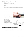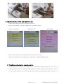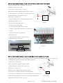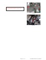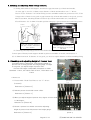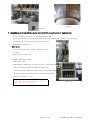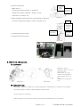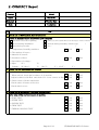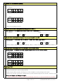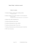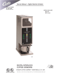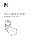
1
MA-6
Installation manual
A table of contents
1. Checking installation condition before installing machine
(1) Installation condition
2. Machine installation and checking condition of external appearance
(1) Fixing a machine.
(2) Checking X-Frame movement whether there is any interruption or
3. Machine motion TEST and Running Test.
4. Checking and adjusting needle position.
5. Checking and adjusting Hook setting condition.
6. Checking and adjusting height of Presser foot.
7. Checking and adjusting Upper and bottom dead point of needle bar.
8. TEST work with material.
Page 1 Of 10
(주)SUNSTAR SWF CS CENTER
1.Checking installation condition before installing machine
(1) Installation condition.
1) Temperature.
When machine work:0。~40。C (32。~104。F)
When machine doesn't work (maintenance):-25。~55。C (-13。~131。F)
2) Humidity
Humidity:45~85%
3) Surrounding condition
Please close window and entrance door to prevent sun light and moisture and dust from
coming to machine.
4) Installation place.
Please install machine on flat ground as well as ground is concrete structure which is enough
to bear machine weight without bumpy.
5) Main power : 1Ø 100~240V 50~60Hz ±10%
2. Machine installation and checking condition of external appearance
(1) Fixing a machine.
- Without exclusive stand
In case not using exclusive stand,
please adjust level on all posions
(lift-right, front-back) with level adjusting bolt.
- With exclusive stand
In case using exclusive stand,
fixing machine on stand table.
4 antivibration rubbers are placed under
under level adjusting bolt and adjust level
Fixed nut
Level adjusting bolt
adjust bolt until caster is over ground.
Left and right and front, back of machine
Antivibration rubber
Caster
should level off as using level gauge.
(2) Checking X-Frame movement whether there is any interruption or not.
1) Before turn on the machine, checking X-Frame movement whether theris is any interruption or no
(limit sensor, sensor bracket, dust, etc) If there is any interruption, remove obstacle for moving X-F
Page 2 Of 10
(주)SUNSTAR SWF CS CENTER
3. Machine motion TEST and Running Test.
1) After fixing machine, perform machine motion test.
If there is any problem, connect to SWF agent for solving problem.
TOOLS -> MACHINE
MACHINE TEST
TEST MENU
Perform each test function whether machine works normally or not.
(JUMP TEST, WIPER TEST, PICKER TEST, TRIM TEST, THREAD SENSING TEST)
4. Checking and adjusting needle position.
* Checking needle position : First, change a color as placing that middle needle bar is on center. An
checking needle position as downing middle needle bar. (Degree of Main shaft is between 130 and
* In case needle position is not normal, please adjust needle position again. Reference [Picture 1, a
Page 3 Of 10
(주)SUNSTAR SWF CS CENTER
How to adjust needle position, in case Front and back of needle position is not good.
1)Degree of Main shaft is between 130 and 140˚.
2)Release 3 Head rail screws
b
to use 3mm T-wrench and "-" driver
When disassemble middle head rail screw, presser foots
of 3,4 needle bar is prevented. So, down presser foots
of 3,4 needle bar, and release screw.
Good
position
Reference to [Picture-2]
* Confirm whether there is head rail gauge beteen
head Rail and Head, or not.
[Picture 1]
①In case head rail gauge exist
a) Remove head rail gauge.
②In case head rail gauge doesn't exist.
a) Replace head rail to use 3mm T-wrench and
"-" driver.
* The sort of thickness of head rail
Standard:5.4mm
(-)gauge[special gauge]:5.3mm,5.2mm
3) Assemble head rail screws.
Head rail screw
Head rail
[Picture 2]
Head rail gauge
How to adjust needle position, in case left and right of needle position is not good.
* Checking needle position : First, change a color as placing that middle needle bar is on center. An
checking needle position as downing middle needle bar.
* Reference to [Picture-3]
How to adjust left and right needle position
1) Disassemble 5 screws of Arm cover (L).
Reference to [Picture-4]
2)Release color change fixing bolt(two) a little,
(to use 4mm T-wrench) and adjust needle position
Good
as moving color change box to left and rig Reference to [Picture-5]
3)After adjusting position, fasten two color change fixing bolts.
[Picture-3]
4)Assemble 5 screws of Arm cover (L).
Page 4 Of 10
(주)SUNSTAR SWF CS CENTER
Caution - If needle position is not correct, it will be
caused needle damage. So you have to adjust needle
position correctly with head rail gauge of proper
thickness.
[Picture 4]
[Picture 5]
Page 5 Of 10
(주)SUNSTAR SWF CS CENTER
5. Checking and adjusting Hook setting condition.
(1) Fixing main shaft to 200 degree, and check a gap between tip of hook and needle.
(In case gap is over 0.1~0.3mm, reset distance of hook and needle to use "-" driver.
How to reset : Release 2 of 3 hook fixing screws at middle needle bar position.(at 135, 75 de
If tip positon of hook is not good or gap between tip of hook and needle is not good, you nee
After reset them, checking distance between tip of hook and needle at 1,6 needle bar.
(Good Distance :0.1~0.3mm) If needle position and gap is good, fasten two hook fixing screw
(Needle)
(Point of Rotary
Hook)
ROTARY
HOOK
SUPPORT
Tip of hook should be placed on
back side of needle, and distance
is 0.1~0.3mm.
Convex part of Rotary hook support
should be placed on middle of
needle, and distance is 0.5~0.7mm
with hook
(2) Checking and adjusting position of ROTARY HOOK SUPPORT.
Convex part of Rotary hook support should be placed on middle of needle, and distance is
0.5~0.7mm from hook. If distance is not good, you need to adjust distance as disassembling fixing
6. Checking and adjusting height of Presser foot.
Turn Main shaft to 180 degree, and checking height of
presser foot as using presser foot height gauge. If height
is not good, you adjust height of presser foot.
※ Presser foot height is adjustable,it depends on fabric
Standard :1.0mm, thin fabric:under 0.7mm, Thick fabric: over
1.2mm
* How to se
1) Disassemble Head Face Plate to use "+" driver.
[Picture 6]
(4 screws)
Reference to [Picture-6]
2) Release presser foot holder screw a little.
Reference to [Picture-7]
3) When you adjust height of presser foot, degree of main shaft
is 180 degree.
Reference to [Picture-8]
4) Fasten a presser foot holder screw after adjusting
height of persser foot with presser foot height gauge.
[Picture 7]
Reference to [Picture-9]
Page 6 Of 10
(주)SUNSTAR SWF CS CENTER
[Picture 8]
[Picture 9]
7. Checking and adjusting Upper and bottom dead point of needle bar.
* Move to middle needle bar on 180 degree(Main shaft)
Check a gap between Jig and Upper dead point after inserting Jig. If there is a gap or Jig
is not inserted, you need to reset Upper dead point.
Reference to [Picture-11]
How to set
1) Disassemble head face plate. Release 4 screws
"+" driver
Reference to [Picture-10]
2) Upper dead point setting.
① Main shaft 180˚
②Using Bottom dead point jig, please fasten a "needle bar holder
screw" after pushing down needle bar fixing holder.
After fastening a needle bar holder screw, please check whether
Jig move smoothly between bed and "Needle fixed holder".
Reference [Picture 11, 12]
Caution) when fastening needle bar fixing screws,
pervent needle hare from deformation
Page 7 Of 10
[Picture 10]
(주)SUNSTAR SWF CS CENTER
3) bottom dead point
Needle
Fixed
Holder
①Main shaft 0˚
②"Upper damd point stopper" is pushed to
"Needle bar cushion rubber B", fasten a screw.
Set Up
Gauge For
Needle Drop
Point
Reference to [Picture-12]
[Picture 11]
4) After changing needle bar(color) with avoiding reciprocator,
you check needle bar whether it works smoothly or not.
Head
Needle Bar
Cushion
Rubber B
Upper Dead
Point Sopper
3. Assemble head face plate
Needle Bar
Holder
1) Assemble head face plate
[Picture 12]
[Bottom dead point Jig
8. TEST work with material.
(1) Lubrication
[Picture 13]
[Picture 14]
When we send a
machine, there is no oil
in oil box for
lubricaiton. So, you
need to test machine
after putting oil in oil
box.
Reference to [Picture14]
(2) embroidery test
※ Checking a machine condition as testing with fabric and thread of customer, test design.
Checking Dadami condition and trimming, thread break.
※ Test a design of customer.
※ When testing to work, teach customer operation and maintenance of machine.
Page 8 Of 10
(주)SUNSTAR SWF CS CENTER
E-COMPACT Report
Country
Model
Agent
Serial No.
Company
Version Date
Date
Technician
List
Order
1 Check List of Environment before instalation
Status of machine before it arrived at your company
Start from Wood box Opening
When you arrived,machine was moving to inside of factory
Arrived during installation
Arrived during assembly (which setp:
After whole procudre
etc, (
)
)
(1) Temperature/ humidity,ambience
good
bad
good
bad
(2) The number of layers :
(3) Material of bottom :
(4) Levelness of floor
(5) Speculation of voltage :
(6) Input
Voltage :
1P (
V)
3P (R↔S :
V)
(R↔T :
V)
(S↔T :
V)
2 Check List for installation and exterior
(1) Safe Arrival
- When arrived, check the levelness of of machine
good
bad
- Adjust levelness with Bolt and check (if it is not correct at first)
good
bad
- Check status of frame at first site
good
bad
- Check debris or not
good
bad
(1) JUMP TEST
good
bad
(2) WIPER TEST
good
bad
(3) PICKER TEST
good
bad
(4) TRIM TEST
good
bad
(5) THREAD SENSING TEST
good
bad
(2) Check status of frame and debris
3 Check list for movement TEST and Running TEST
After safe arrival,test movement of machine
Page 9 Of 10
(주)SUNSTAR SWF C/S Center
4 Check B.D.P status and adjusting
① Before
NEEDLE
1
2
3
4
5
6
1
2
3
4
5
6
NEEDLE POINT
② After
NEEDLE
NEEDLE POINT
※ When insert guage,record it.
5 Check list for Hook timimg and adjusting(good:O, bad:X )
Hook timing 201 °, No gapss with Needle, more than 0.3mm,reset it.
① Before
② After
good
bad
good
bad
6 Check list for checking the Pressor Foot and set (good:O, bad:X )
General Head - If needle bar(180 °) is out of 1.2mm from Upper Face,reset it.
① Before
② After
good
bad
good
bad
※ Able to adjust ,depends on product (delivery Data : 1.2mm, Thin Fabric:0.7mm, Thick Fabric:1.2m
7 Check list for checking Upper Dead/Needle position and setting
General Head - If Needle point 201°,Upper Dead Point 0° is not correct,reset it.
① Before
NEEDLE
1
2
3
4
5
6
1
2
3
4
5
6
UPPERDEAD
POINT
NEEDLE POINT
② After
NEEDLE
UPPERDEAD
POINT
NEEDLE POINT
8 Sewing TEST.
※ Test with thread and fabrick from your company and check Status of machine
Check Nomalization status,cutting thread
(If the Agent didn't prepare desing,test it with workplace sewing design and check)
※ When test Sewing, check the cutting thread, work timek,missing the first needle and then report
Attach the Sample and Design to report.
※When Sewing TEST,train the worker and manager that how to operate/maintain the machine.
Page 10 Of 10
(주)SUNSTAR SWF C/S Center