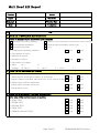
1
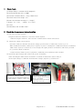
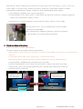
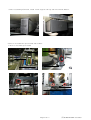
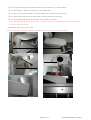
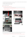
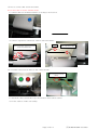
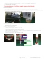
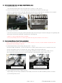
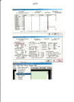
SB Multi Heads Series Installation Manual
Index
1. Check Tools
2. Check the circumstances before installing
3. Check and adjust levelness.
4. Assembly
(1) Install Y fixed Frame
(2) Install the table
(3) Assemble Spool Stand and OP Box
(4) Assemble the Frame
(5) Assemble the bar switch and connetc cable
(6) Assemble the Offset Switch clear the cable
5. Running the machine without needle
6. Check the levelness and assemble the Table Support
7. Check the needle position and correct it
8. Re-set the upper dead & needle point of needle bar
9. Check and correct the Rotary Hook
10.Test the machine operation and Running
11.Test the Sewing
Page 1 Of 17
(주)SUNSTAR SWF CS Center
1
Check Tools
(1) Height Guage (1 needed include indigator)
(2) Set the Needle bar JIG (17.7MM)
(3) Precision Level(2/100mm, 1 Q'ty), Water Hose.
(4) Presser Foot Level Guage (1T)
(5) B.D.P JIG and B.D.P Guage.(+,- Guage)
(+ Guage: 0.1 / 0.2T , - Guage: 4.3 / 4.0T )
(6) Tester
(7) Embroidery A/S Tool Box 1SET
2 Check the circumstances before installing
(1) Safe arrival of the machine
Weight of SB Series machine is 3.0t (Not include Option) .
※ When moving the machine , must use the a forklift truck at least 5Ton above
(2) Check the voltage specifications
Open the Contl box and then check the voltage specifications of embroidery (refer to pic 2)
When install the machines, Main power capacity of power consumption is 3KW(official) but recommend
5KW. If the capacity of electricity is not enough, the right operation of machines will not be possible.
So, you must check in advance.
※ Under 3 Phase/ 5KW of power equipment , additonal power build up will be needed
(3) Check the input voltage and connect the power of machine.
After checking the Main Switch of machine is turned off Check the status of R,S,T .
(If the input voltage is different from machine voltage, adjust it by control box)
R
S
T
Check the all status of voltage
(R,S),(S,T),(R,T).If operating voltage of
the input voltage is +10% to -10% is fine.
If you want to change the
machine voltage specifications
insert it to voltage
specification which you want to
change the connector
Pic 1
Pic 2
Page 2 Of 17
(주)SUNSTAR SWF CS Center
Check the all status of voltage (R,S),(S,T),(R,T). (operating voltage of the input voltage is +10% to -10% is fine)
If the voltage is out of the scope, inform to the factory worker for correcting the problem of voltage.
Install general AVR(Automatic Voltage Controller or UPS (Uninterruptible Power Supply)
1) Recommend to install the AVR , capacity 5KW above.
2) If the machines are too much ,which is connected to the AVR at the same time ,install the additional
supplies after checking the capacity of AVR.
※ If Sequin Device is already installed, use the compressor whose capacity is above 1Mpa.
After put out the Nob , set it by turning right or left for 0.6Mpa.
(Setting errors:±0.05Mpa)
After confirming the simultaneous algebraic connected equipment,
if capacity(Mpa) is not enough, build up additional.
3
Check and Adjust of levelness.
# Not for less then Y-Storke 850mm model
(1) Inspect outside of the machines and level the machine
※ When leveling by using water hose, check the air insertion in the middle of water hose, do not squeeze and
walk on it.
※ Do not put the Level Guage on the square pipes or table when leveling.
※ When leveling (L/R), check the variation of water from the hose,if it was changed, adjust it.
1) Levelness(L/R) : Installation must be under error scope 5mm
2) After checking that there are no debris on the base level ,install it with 2/100 error guage
(Based oh the center, left and right within three grid , left and right within 6/100 tolerances)
3) Check levelness of L/R, F/R
As indicated by noted ,
Leveling level it with a
water level L/R,F/R.
As indicated by noted ,
Leveling level it with a
water level L/R,F/R.
Beam Body(left)
Adjusting height with lifting
tools
Page 3 Of 17
Beam Body(right)
(주)SUNSTAR SWF CS Center
X
O
Level it less than 0.5mm
error scope for equaling the
height of "0" mark and Body
id
When leveling(F/R), within
tolerances
Height difference
within 10mm
Keep the space
1.5mm (minimum)
Leveling Base
Install it bottom of the Leveling Base and Body
within 10MM,if the difference is big,
Add the iron plate for adjusting.
(Attach the picture of this in the report)
When leveling the water, Hex.Bolt will get a lot of loads, so,
put up the Beam Body with lifting tools for adjusting the
height
and then put down the Hex Bolt
"B"
"A"
When leveling the water, equaling the water(inside of hose) and Body side based on "A".
If the height of water is above the Body side, put up machines with lifting tools for leveling.
If the height of water is below the Body side, place the base "A" to "B" for leveling.
Page 4 Of 17
(주)SUNSTAR SWF CS Center
4
Assembly
(1) Install Y fixed frame
# Not for less than Y-Storke 1200mm model (Because it is not delivered as Fixed Frame.)
1) Don't mix the position of attaching.
2) Pre-connect Fixed Frame Plate Bolt with Y Fixed Frame Bolt and then fix the position of Y Frame Fixed Connecting Plate
Be cautious that turn aside to the left,right of Y Frame when connecting Fixing Bolt .
Check the declension(up/Down) and turning aside to the L/R of being fixed Y Frames with naked eyes.
In case of the table which is on the edge of front and right, assemble the Table Support,
because it is seperated with the Table Plate and Table Support respectively.
Insert Table Supporting Connecting Bar to the Table Support which is fixed to Beam Body,
and fix the Table Fixing Support Screw close by.
Page 5 Of 17
(주)SUNSTAR SWF CS Center
(2) Assemble the Table Plate
# Above the Y-Storke 850mm model, assemble the plate
1) Refer to the sticker, assemble it in the right position.
2) Equal to the position of Table and plate and push the plate to the Table for connecting the Table piece.
Connect the Table Support with Table Support Connecting Bolt(M10,L30) for fixing.
3) Connect Table Connecting Plate and Table Support with Bolt.
Table Support
4) Check the height of Table connection and correct it.
Set correctly for showing a plane figure of table connection.(table d-party washer 0.3,0.5,0.8,1.0 )
Page 6 Of 17
(주)SUNSTAR SWF CS Center
5)After assembling F/R Table ,install Table Support end Cap and Fixed Frame Rubber.
(3)How to Assemble the Spool Stand and OP BOX
1) How to Assemble Spool Stand
Page 7 Of 17
(주)SUNSTAR SWF CS Center
① Insert Spool Stand to Spool Stand Stud.(Insert Spool Stand "A" to Tension Plate )
② Fix Angle Base to Angle "D".(connect it with M4L10 Bolt)
③ Connect Spool Stand with Angle Set.(Insert Spool Stand to Angle Frame groove)
④ Fix Angle Frame Hall to Spoon Stand with Fix Bolt.(with 4mm T-Wrench)
⑤ Fix Spool Stand Stud Bolt to Spool Stand .(with 2.5mm L-wrench)
※ If Spool Stand/Angle and Fixed Bolt are not connected correctly, vibration from Spool Stand and Angle
seems like harder than real.
2)Attach OP BOX and connect Cable.
#Not for less than Y-Storke 1200mm model (Because it is not seperated from Op.Box)
Page 8 Of 17
(주)SUNSTAR SWF CS Center
① Set through the Signal Cable and E-switch Cable of OP BOX to OP BOX Stand,and assemble OP BOX Stamd.
② Wire the OP BOX Cable and Emergency swich Cable.
③ Attach the Table Cover.(with "+"driver)
④ Fix OP BOX Stand.(with 4mm T-wrench)
(4) How to assemble the Frame
#Not for less than Y-Storke 1200mm model.
※ Move Frame toward Y direction for checking the interrupting of Frame and Frame Bearing from F/R
※ Check and adjust height of Frame Bearing and levelness.
(If levelness of Bearing is not good, when you moving it toward F/R, it can be broken by interrupting
E Frame to Frmae Bearing )
※ If you insert E Frame by force, it can be broken by resistance from Frmae Bearing.
Frame E Fiixing Bolt
(4each part,8EA)
When connecting Frame E Fixing Bolt , pre-connect first, move Frame Up and Down and then connect it.
After connecting Frame, connect X-Shaft Couling.(2 each) with 5mm,3mm T-wrench.
※ If Frame E and Coupling Screw are not connected exactly, out of step and cutting will be happened.
Page 9 Of 17
(주)SUNSTAR SWF CS Center
(5) How to connect Bar Switch and Cable.
# For more than Y-Storke 850mm model.
1) Connect Bar Swich Holder and Box according to the location.
2) Connect Signal lines and Power Cable to Bar Switch Box.
클램프
Clamp
Wire Power Cable ,Signal Line,Earth
to No.9 Bar Switch Bos.
9-1
Connect
바스위치
Signal
박스에
Lines신호
to
No.9-1
선을Bar
연결한다.
Swtich Box.
(6) Assemble offset Switch and wire the cables.(6each)
Wire the Signal Lines with
Clamp.
1) Attach the Offset Switch Box specified location and connect Cables.
2) Fix the Cable to Table with Clamp.
Page 10 Of 17
(주)SUNSTAR SWF CS Center
5
Running without Needle
1) Oiling the essential part
Arm,Head,Rotary Hook,(Pic
1~4)
2) With normal sewing wroking
test design,run the machine at
600 RPM
3) Check Point: Bearing Bushing
seperation, Shaft heat, noise
from frame/each belt part.
4) Check vibration from machine.
5) After finishing Running Test,
check status of machine.
6
How to check level status and instal Table Support
(1) Leveling L/R :With water Hose, adjust less than error scope 0.5mm .
(2) Leveling F/R :Use error scope 2/100 level (by the central, left and right, within three grid )
As indicated by noted ,
Leveling it with a
water level L/R,F/R.
As indicated by noted ,
Leveling it with a
water level L/R,F/R.
Beam Body
id (l f )
Adjusting the height with lifting
tools
Beam Body side(right)
X
O
Level it less than 0.5mm error
scope for equaling the height of
0 mark and Body side
Install it bottom of the Leveling Base and Body
within 10MM,if the difference is big,
Add the iron plate for adjusting.
(Attach the picture of this in the report
When leveling(F/R), within tolerances.
When leveling the water, Hex.Bolt will get a lot of
loads, so, put up the Beam Body with lifting tools for
adjusting the height and then put down the
H B l
Page 11 Of 17
(주)SUNSTAR SWF CS Center
※ Variation of needle postion from level status of machine may causing the Cutting thread,
So, check throughly and handle it.
Contraction and expension of Dust Pad may change the levelness,so check it throughly.
(3) How to fix Hex.Bolt
When fixing Hex.Bolt,open Needle Plate from the Head, fix Main Shaft at 201 degree.And then,
put down Needle Bar for inserting Needle Point Jig,check the gap how much jig is inserted to bottom of Needle
Fixed Holder for deciding the amount of Hex.Bolt.
(4) Check Body Support Bolt from Beam Support and fix it. With iron and rubber plate,
adjust the height of Leveling Base.
(5) How to install Table Support
1.Connect Table Supporter Bracket to the Table.
2.Insert Table Surpporter to Table Surpporter Bracket
3.When instal the Table Supporter, be cautious of declension and when it's upper part contact to set up
potion, turn it less than 270˚ and fix it.
4.Connect Table Supporter Nut. (23mm,nut, 2 each)
Surface
Table Supporter
Turn it less than 270˚
Page 12 Of 17
(주)SUNSTAR SWF CS Center
7
How to check Needle Position and correct.
(1) Check Head gap
Open the
M3 Bolt and
set head
gap.
1) Check F/R gap from No.3 Needle Bar
2) Change the Needle Bar by No.1 needle bar
3 If F/R gap occurred,with M3 Wrench,set the
gap scope under 0.1mm(minimum)
※ If head gap is too much,Cutting Thread and
needle broking may occur. If gap is too
less,resistance problem will be happened( C/C).So
set the machine as minimum gap of it.
(2) Check Needle Position
1) Set the L/R Needle Position first and then F/R after.(with 3mm T Wrench)
If it is on ③ ,change the Head Rail for small one for adjustiong position.
If it is on ④, insert Gage of B.D.P between Head Rail and Head for adjusting.
2)After adjusting,check needle position between No.1 Needle and Last Needle.
The hall size of Zig is length,width each
1
If it is placed ①,②, loosen the COLOR
CHANGE SHAFT BRACKET Bolt for adjusting
Needle position L/R.
Head Rail Bolt
COLOR CHANGE
SHAFT BRACKET
When adjusting ③,④ position, loosening
Head Rail Bolt (3 each)3mm with Twrench.
Replace 4.5T
4.3 ,4.0 T as base
thi k
Head Rail Guage
If the needle is on ④, insert Guage to
between Head Rail and Head
for adjusting.(with 0.1T,0.2T,0.3T)
If the needle is on the ③ ,replace it with thin
Head Rail for adjusting.
Page 13 Of 17
(주)SUNSTAR SWF CS Center
8
How to check and reset the Upper Dead /Needle point.
(1) Check Needle Point
Turn the Main Shaft and put down Needle Bar for fixing it as 201 degree.
(2) Insert Needle Point JIG to between Bed Upper Head and bed and then check the gap.
If there is a gap,loosen the Needle Bar Bolt,push and down the Needle Bar for attaching to JIG, Tighten
Needle bar Bolt with T-Wrench .Shake JIG Up/Down for checking the gap.
(3) Set Upper Dead Point
1)Fix the main shaft as 0 degree,push Needle Bar and put up the Upper Dead Point Stopper for tightening Bol
Grab Upper Dead Point and shake it up/down for checking gap.
If there is a gap, Needle Bar will be stumble.
Don't put up hardly and set for without gap.(When driving, these matters cause noise)
9
How to check Rotary Hook Timing and adjust.
※ Before setting the Rotary Hook, check the Needle twisted or not first, set the Needle forward direction
(Optimized Loop formating Condition)
(1) Check/adjust Rotary Hook timing and gap.(with "-" driver)
From the middle Needle Bar , loosen 2(each)screw of Rotary Hook Fixed Screw 3 each(near 135°,75°).
Fix the main Shaft at 201° for checking the Point of Rotary Hook and Needle,gap.
If Point of Rotary Hook is not correct or gap(Needle and Rotary Hook) is big or too small, reset it.
After finish the setting,check First to Last Needle Bar of gap.And then tighten whole Screw.
Rotary Hook
Adjust bulge part for being on Middle
of the Needle, interval 0.5~0.7mm
with Rotary Hook is needed.
Set Rotary Hook Point behind
Needle Bar at 0.1~0.3mm interval.
(2) Check/adjust the position of Rotary Hook.
Adjust bulge part for being on Middle of the Needle, interval 0.5~0.7mm with Rotary Hook is needed
,by loosening Fixed Screw.
Page 14 Of 17
(주)SUNSTAR SWF CS Center
10 How to test machine operation and Running Test.
(1) Machine operation TEST.
1) Test in/output of design with FDD and USB. (Chcek the way of formation USB user, FAT format O.K , FAT32 format
2) Test Bar Switch and offset Switch correctly.
3) Test Jump Motor movement (Check the 0.3 MM gap of reciprocator and Jump Motor)
by testing Jump movement, check motor,cable,Thread Board,Join Board,SMPS,operation,indirectly.
4) Check movement of each Wiper and carry over of blade(wiper),if it is not correct ,reset the Pressure Base.
5) By testing for each Picker movement,check Solenoid and position of picker entrance amount.
6) Check Upper Thread Holding and Holiding equipment amount and adjust it.
7) Check Trim Motor movement and Thread Moving Mess movement return position.
8) Check Thread Board and related Cables also.
9) When driving Frame, check the Table Connecting Cover and interruption and noise.
Check the working range is fit for mechanical specifications. Check position of sensor and adjust it.
10)Test movement of Needle Bar Up/Down.(check the status of Jam)
(2) Running Test.
1) Driving the machine at 900~1000 RPM (about 1 hour), and then check vibration,heat from
DrivingParts,Frame and other related parts.
2) After Running Test, check the status of machine.
11 Sewing TEST.
※ Test with thread and fabrick from your company and check Status of machine
※ Test design your esteemed company.
Write productivity report.Attach the Sample and Design.
※When Sewing TEST,train the worker and manager that how to operate/maintain the machine.
Page 15 Of 17
(주)SUNSTAR SWF CS Center
Multi Head E,K Report
Country
Model
Agent
Serial No.
Company
Version Date
Date
Technician
List
Order
1 Check List of Environment before instalation
Status of machine before it arrived at your company
Start from Wood box Opening
When you arrived,machine was moving to inside of factory
Arrived during installation
Arrived during assembly (which setp:
After whole procudre
etc, (
)
)
(1) Temperature/ humidity,ambience
good
bad
good
bad
(2) The number of layers :
(3) Material of bottom :
(4) Levelness of floor
(5) Speculation of voltage :
(6) Input
Voltage :
1P (
V)
3P (R↔S :
V)
(R↔T :
V)
(S↔T :
V)
2 Check List for installation and exterior
(1) Safe Arrival
- When arrived, check the levelness of of machine
good
bad
- Adjust levelness with Bolt and check (if it is not correct at first)
good
bad
- Check status of frame at first site
good
bad
- Check debris or not
good
bad
(1) JUMP TEST
good
bad
(2) WIPER TEST
good
bad
(3) PICKER TEST
good
bad
(4) TRIM TEST
good
bad
(5) THREAD SENSING TEST
good
bad
(2) Check status of frame and debris
3 Check list for movement TEST and Running TEST
After safe arrival,test movement of machine
Page 16 Of 17
(주)SUNSTAR SWF C/S Center
4 Check B.D.P status and adjusting
① Before
Head
Needle
1
2
3
4
5
6
7
8
9 10 11 12 13 14 15 16 17 18 19 20 21 22
1
2
3
4
5
6
7
8
9 10 11 12 13 14 15 16 17 18 19 20 21 22
First
Middle
Last
② After
Head
Needle
First
Middle
Last
※ When insert guage,record it.
5 Check list for Hook timimg and adjusting(good:O, bad:X )
Hook timing 201 °, No gapss with Needle, more than 0.3mm,reset it.
① Before
② After
good
bad
good
bad
6 Check list for checking the Pressor Foot and set (good:O, bad:X )
General Head - If needle bar(180 °) is out of 1.2mm from Upper Face,reset it.
① Before
② After
good
bad
good
bad
※ Able to adjust ,depends on product (delivery Data : 1.2mm, Thin Fabric:0.7mm이하, Thick Fabric:1
7 Check list for checking Upper Dead/Needle position and setting
General Head - If Needle point 201°,Upper Dead Point 0° is not correct,reset it.
① Before
Needle Bar
1
2
3
4
5
6
7
8
9 10 11 12 13 14 15 16 17 18 19 20 21 22
1
2
3
4
5
6
7
8
9 10 11 12 13 14 15 16 17 18 19 20 21 22
Upper Dead
point
Needle Point
② After
Needle Bar
Upper Dead
point
Needle Point
8 Sewing TEST.
※ Test with thread and fabrick from your company and check Status of machine
Check Nomalization status,cutting thread
(If the Agent didn't prepare desing,test it with workplace sewing design and check)
※ When test Sewing, check the cutting thread, work timek,missing the first needle and then report
Attach the Sample and Design to report.
※When Sewing TEST,train the worker and manager that how to operate/maintain the machine.
Page 17 Of 17
(주)SUNSTAR SWF C/S Center