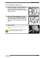
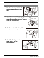
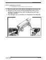
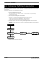
1
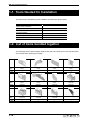
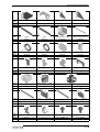
AMF Unit
Installation Manual
Revision 1.0
MIMAKI ENGINEERING CO., LTD.
TKB Gotenyama Building, 5-9-41, Kitashinagawa, Shinagawa-ku, Tokyo 141-0001, Japan
Phone : +81-3-5420-8671 Fax : +81-3-5420-8687
URL : http://www.mimaki.co.jp/ E-mail: [email protected]
D500375-10
AMF Unit Installation Manual
About this Installation Manual
This document is written for service engineers, and contains a set of installation procedures that
are needed when fitting an AMF unit to a JV5-130S/160S inkjet printer.
During installation, perform work by referring to this document and the following related
manuals.
Structure
This manual consists of the following chapters.
Chapter 1:Overview
Describes the tools that are used to install the AMF unit.
Chapter 2:Installation Procedure
Describes the procedure for installing the AMF unit.
Documents related to this unit
The following is a list of documents other than this manual that describe the JV5-130S/160S.
Refer to these as necessary.
• Operation Manual (included with the product)
• Mechanical Drawing
• Maintenance Manual
ii
Contents
Chapter 1 Overview
1-1. Tools Needed for Installation ....................................................................... 2
1-2. List of items bundled together ..................................................................... 2
Chapter 2 Installation Procedure
2-1. Installation Overview .................................................................................... 2
2-1-1. Warnings During Installation ............................................................... 2
2-2. Installation Overview .................................................................................... 3
2-3. Assembling the AMF Unit ............................................................................. 4
2-3-1. Attaching leg reinforcement plates R/L ............................................... 4
2-3-2. Attaching the hanger BKT ................................................................... 4
2-3-3. Attaching the take-up T bar base R assy. ........................................... 5
2-3-4. Attaching the take-up T bar base L assy. ............................................ 6
2-3-5. Attaching the feeding T bar base R/L assy. ........................................ 6
2-3-6. Attaching the take-up drive unit R assy. .............................................. 7
2-3-7. Attaching the take-up drive unit L assy. .............................................. 9
2-3-8. Attaching the feeding drive unit R assy. ............................................ 10
2-3-9. Attaching the feeding drive unit L assy. ............................................ 12
2-3-10. Assembling the feeding/take-up T bar .............................................. 12
2-3-11. Attaching the take-up T bar ............................................................... 13
2-3-12. Attaching the feeding roll unit ............................................................ 14
2-3-13. Attaching the feeding T bar ............................................................... 15
2-3-14. Installing the waste ink tank unit ....................................................... 16
2-3-15. Installing the roll shaft ....................................................................... 19
2-3-16. Checking the path length (left and right) of the transport surface ..... 20
2-4. Configuring the firmware parameters ....................................................... 22
2-5. Testing the connection after installing the AMF ...................................... 23
2-6. Error messages related to the AMF ........................................................... 25
iii
Color Inkjet Printer JV5-130S/160S
iv
Chapter 1 Overview
Contents
1-1. Tools Needed for Installation .......................................................... 1-2
1-2. List of items bundled together ....................................................... 1-2
1-1
AMF Unit Installation Manual
1-1. Tools Needed for Installation
The tools that are needed during the installation procedure are shown below.
Name
Comments
Phillips-head screwdriver
Hexagonal wrench
Across flats: 6.0, 5.0, 4.0 mm
Spanner wrench
Across flats:19.0mm
Protective glasses
Wipe cloths (Bemcot, etc.)
Gloves
For dirt prevention and safety
1-2. List of items bundled together
The followings are the parts bundled together with AMF unit. Make sure to check that all parts
are included when opening the package.
Name of
parts
Parts No.
Quantity
Take-up T bar base R
ASSY
Take-up T bar plate L
ASSY
Take-up T bar base L
ASSY
Take-up T bar fixation BKT
ASSY
M008014
1
M008015
1
M008016
1
M008017
2
Name of
parts
Parts No.
Quantity
Feeding T bar base R
ASSY
Feeding T bar plate L
ASSY
Feeding T bar base L
ASSY
Feeding device R AMF
total assy
M008020
1
M008021
1
M008022
1
M008040
1
Name of
parts
Parts No.
Quantity
Take-up device R AMF
total assy
Feeding device L AMF
total assy
Take-up device L AMF
total assy
T bar auxiliary BKT R
M008041
1
M008042
1
M008043
1
M510111
1
1-2
List of items bundled together
Name of
parts
Parts No.
Quantity
T bar auxiliary BKT L
Hanger BKT
Leg reinforcement plate R
Leg reinforcement plate L
M510112
1
M507414
2
M510017
1
M510016
1
Take-up/feeding installation
plate L
Waste tank base ASSY
Waste ink discharge tube
M206010
1
M008058
1
M905668
1
Roll holder stopper RH
Roll holder stopper LH
Roll guide shaft spacer A
Waste tank harness cover
M008258
1
M008259
1
M206019
1
M510092
1
Waste ink tube hang stay
Discharge tube stay
Discharge tube holder
Tube hold plate
M510046
1
M508559
1
M508560
1
M510049
1
3 inch roll holder F
3 inch roll holder R
M602301
4
M602302
4
Name of Take-up/feeding installation
plate R
parts
M206011
Parts No.
1
Quantity
Name of
parts
Parts No.
Quantity
Name of
parts
Parts No.
Quantity
Name of
parts
Parts No.
Quantity
Name of
parts
Parts No.
Quantity
Name of
parts
Parts No.
Quantity
M008055
1
Waste tank sensor cable
Assy
E105338
1
Installation BKT A RH
(for 130)
M510307
1
Installation BKT B RH
(for 130)
M510308
1
Installation BKT A LH
(for 130)
M510309
1
Installation BKT B LH
(for 130)
M510310
1
Roll holder AMF
Cable clip
Screw
Screw
M008277
1
UC - 1.5
2
P3 × 10SMW(白)
4
P4 × 12SMW
47
Tube joint ASSY
1-3
AMF Unit Installation Manual
Name of
parts
Parts No.
Quantity
Name of
parts
Parts No.
Quantity
Name of
parts
Parts No.
Quantity
Hex bolt
Hex bolt
Hex bolt
Hexagon wrench (4mm)
CS5 × 10SMW
10
CS6 × 20
8
CS8 × 20
16
APL-04
1
Hexagon wrench (5mm)
Hexagon wrench (6mm)
Installation manual
(for English)
AMF Operation manual
(for Japanese)
APL-05
1
APL-06
1
D500375
1
D201838-11
1
AMF Operation manual
(for English)
D201839-11
1
Bundled parts for JV5-160
Name of
parts
Parts No.
Quantity
T bar 1895
Roll mesh
Roll shaft 160 AL Assy
M206012
2
M602294
4
M008206
2
Bundled parts for JV5-130
Name of
parts
Parts No.
Quantity
1-4
T bar 1637
Roll mesh 130
Roll shaft 130 AL Assy
M206030
2
M602303
4
M008207
2
Chapter 2 Installation Procedure
Contents
2-1. Installation Overview ....................................................................... 2-2
2-1-1. Warnings During Installation .............................................................. 2-2
2-2. Installation Overview ....................................................................... 2-3
2-3. Assembling the AMF Unit ............................................................... 2-4
2-3-1.
2-3-2.
2-3-3.
2-3-4.
2-3-5.
2-3-6.
2-3-7.
2-3-8.
2-3-9.
2-3-10.
2-3-11.
2-3-12.
2-3-13.
2-3-14.
2-3-15.
2-3-16.
Attaching leg reinforcement plates R/L .............................................. 2-4
Attaching the hanger BKT ................................................................. 2-4
Attaching the take-up T bar base R assy. .......................................... 2-5
Attaching the take-up T bar base L assy. .......................................... 2-6
Attaching the feeding T bar base R/L assy. ....................................... 2-6
Attaching the take-up drive unit R assy. ............................................ 2-7
Attaching the take-up drive unit L assy. ............................................. 2-9
Attaching the feeding drive unit R assy. .......................................... 2-10
Attaching the feeding drive unit L assy. ........................................... 2-12
Assembling the feeding/take-up T bar ............................................. 2-12
Attaching the take-up T bar ............................................................. 2-13
Attaching the feeding roll unit .......................................................... 2-14
Attaching the feeding T bar ............................................................. 2-15
Installing the waste ink tank unit ...................................................... 2-16
Installing the roll shaft ...................................................................... 2-19
Checking the path length (left and right) of the transport surface .... 2-20
2-4. Configuring the firmware parameters .......................................... 2-22
2-5. Testing the connection after installing the AMF ......................... 2-23
2-6. Error messages related to the AMF ............................................. 2-25
2-1
Color Inkjet Printer JV5-130S/160S
2-1. Installation Overview
This chapter describes the procedure for installing the JV5-130S/160S.
Carefully read and understand this document and all related documents before beginning the installation
work.
2-1-1. Warnings During Installation
Make sure that you fully understand all of the following warnings before beginning work.
z Always turn the main power switch (rear panel of the main unit) off prior to work
unless otherwise directed to prevent electrical shocks and circuit damage during the
work. (It is not sufficient to merely turn off the power switch on the front panel)
z Always wear gloves during assembly and disassembly work to prevent cutting injuries.
z When performing work, ensure that there is sufficient surrounding space and perform the
installation in a stable location.
z Be very careful when handling this product as the product is extremely heavy.
z Only use the designated tools when carrying out work.
z Ensure the connections of each connector are securely and fully attached.
2-2
Installation Overview
2-2. Installation Overview
1. Remove the following components from the current device.
Hanger
BKT
Leg reinforcement
plate R
Feeding roll
unit
Take-up device unit
Waste tank unit
Hanger
BKT
Leg reinforcement plate L
• The waste tank unit and feeding roll unit in the diagram are still used after installing the AMF unit.
(Other components are not used)
2. Assembling the AMF unit.
• Assemble each of the following components.
Take-up T bar base L
assy.
Take-up T bar base
R assy.
Feeding T bar base
R assy.
Feeding T bar base
L assy.
Waste tank unit
base AMF
T bar
Roll shaft
Take-up drive unit L assy.
Take-up drive unit R assy.
Hanger BKT
Leg reinforcement
plate R/L
Feeding drive unit L assy.
Feeding drive unit R assy.
2-3
Color Inkjet Printer JV5-130S/160S
2-3. Assembling the AMF Unit
2-3-1. Attaching leg reinforcement plates R/L
1. Attach leg reinforcement plate R.
• Use five CS6 × 20SMW to attach the plate.
Leg reinforcement
plate R
2. Attach leg reinforcement plate L.
• Use five CS6 × 20SMW to attach the plate.
Leg reinforcement
plate L
2-3-2. Attaching the hanger BKT
1. Attach the hanger BKT.
• Use four M4 × 12SMW to attach the bracket.
• Use the screw used for old hanger BKT.
2-4
Assembling the AMF Unit
2-3-3. Attaching the take-up T bar base R assy.
1. Attach the take-up T bar base BKT RA
and the take-up T bar base BKT RB to the
legs of the main unit.
Take-up T bar
base BKT RA
P4 ×
12SMW
(4 pieces)
• Use four P4 × 12SMW and three CS5 × 10 SMW to attach the
brackets.
Take-up T bar
base BKT RB
• As there are no threaded holes in the legs, if you are unable to attach
the take-up T bar base BKT RB, use the additional components as
shown in the diagram on the right.
Installation BKT
A RH (for 130)
M4 × 12SMW
CS5 × 10SMW
(3 pieces)
Installation BKT
B RH (for 130)
CS5 × 10 SMW
(2 pieces)
2. Attach the take-up T bar base R assy. to
the take-up T bar base BKT RA.
• Use three CS5 × 10SMW to attach the assy.
• Handle with care not to break the connector.
Take-up T bar
base R assy.
CS5 × 10 SMW
(3 pieces)
2-5
Color Inkjet Printer JV5-130S/160S
2-3-4. Attaching the take-up T bar base L assy.
1. Attach the take-up T bar base BKT LA and
the take-up T bar base BKT LB to the legs
of the main unit.
Take-up T bar
base BKT LA
P4 ×
12SMW
(4 pieces)
• Use four P4 × 12SMW and three CS5 × 10SMW to attach the
brackets.
CS5 × 10SMW
(3 pieces)
• As there are no threaded holes in the legs, if you are unable to attach
the take-up T bar base BKT LB, use the additional components as
shown in the diagram on the right.
Take-up T bar
base BKT LB
CS5 × 10 SMW Installation BKT
(2 pieces)
B LH (for 130)
Installation BKT
A LH (for 130)
2. Attach the take-up T bar base L assy. to
the take-up T bar base BKT LA.
• Use three CS5 × 10SMW to attach the assy.
CS5 × 10 (3 pieces)
Take-up T bar
base L assy.
2-3-5. Attaching the feeding T bar base R/L assy.
The work to attach the feeding T bar base R/L assy. is performed from the rear panel of the
main unit.
1. Attach the feeding T bar base R assy. to
the legs of the main unit.
• Use two P4 × 12SMW to attach the assy.
• Handle with care not to break the connector.
2-6
Right side of the rear panel of the main unit
P4 × 12SMW
(2 pieces)
Assembling the AMF Unit
2. Attach the feeding T bar base L assy. to
the main unit.
Left side of the rear panel of the main unit
• Use two P4 × 12SMW to attach the assy.
P4 × 12SMW (2 pieces)
2-3-6. Attaching the take-up drive unit R assy.
1. Attach the take-up/feeding installation
plate R to the legs of the main unit.
The side with V
shape groove
comes front.
• Use four CS6 × 20 to attach the assy.
CS6 × 20
(2 pieces)
2. Remove take-up MTR cover upper R.
3. Attach the take-up drive unit assy. R to
the take-up/feeding installation plate R.
• Use four CS8 × 20 to attach the assy.
CS8 × 20
(4 pieces)
2-7
Color Inkjet Printer JV5-130S/160S
4. Fix harness of feeding T bar base R
ASSY.
• Use the included cable clip and fix with P3 SMW.
5. Connect harness of feeding T bar base R
ASSY with feeding driving part R ASSY.
• Pay attention to the connecting direction of the connector.
6. Fix the harness.
Harness fixation
screw
Adjust the harness length and tighten the screw.
Loosening : Moves the harness
Tightening : Fixes the harness
Insert the harness into the U
groove of the plate, and tighten
the harness fixation screw.
7. Adjust the level foot.
• Lower the level foot until it presses the floor lightly and lock it.
8. Attach the take-up MTR cover upper R.
• Use six P4 × 12SMW to attach the cover.
Take-up MTR cover upper R
2-8
P4 × 12SMW
(6 pieces)
Assembling the AMF Unit
2-3-7. Attaching the take-up drive unit L assy.
1. Attach the take-up/feeding installation
plate L to the legs of the main unit.
• Use four CS6 × 20 to attach the assy.
• Fix the take-up installing plate placing the side with V groove to the
front. (Portion indicated with ○ in the drawing at the right)
• Use the countersunk screw hole.
CS6 × 20
(2 pieces)
2. Attach the take-up drive unit assy. L to
the take-up/feeding installation plate L.
• Use four CS8 × 20 to attach the assy.
CS8 × 20
(4 pieces)
3. Adjust the level foot.
• Lower the level foot until it presses the floor lightly and lock it.
2-9
Color Inkjet Printer JV5-130S/160S
2-3-8. Attaching the feeding drive unit R assy.
1. Remove feeding MTR cover upper R
2. Attach the feeding drive unit assy. R to
the take-up/feeding installation plate R.
• Use four CS8 × 20 to attach the assy.
CS8 × 20
(4 pieces)
3. Fix the harness of take-up T bar base R
ASSY.
• Using attached cable clips and fix with P3 SMW.
4. Connect harness of feeding T bar base R
ASSY with feeding driving part R ASSY.
• Pay attention to the direction of the connector.
2-10
Assembling the AMF Unit
5. Fix the harness.
Harness fixation
screw
Adjust the harness length and tighten the screw.
Loosening : Moves the harness
Tightening : Fixes the harness
Insert the harness into the U
groove of the plate, and tighten
the harness fixation screw.
6. Adjust the level foot.
• Lower the level foot until it presses the floor lightly and lock it.
7. Attach the feeding MTR cover upper R.
P4 × 12SMW
(6 pieces)
• Use six P4 × 12SMW to attach the cover.
Take-up MTR
cover upper R
2-11
Color Inkjet Printer JV5-130S/160S
2-3-9. Attaching the feeding drive unit L assy.
1. Attach the feeding drive unit assy. L to
the take-up/feeding installation plate L.
• Use four CS8 × 20 to attach the assy.
CS8 × 20
(4 pieces)
2. Adjust the level foot.
• Lower the level foot until it presses the floor lightly and lock it.
2-3-10. Assembling the feeding/take-up T bar
1. Attach the feeding T bar plate and T bar plate to the T bar 1883.
2. Insert the roll mesh into the T bar 1883.
• Use two P4 × 12SMW to attach each plate.
Feeding T bar
Roll
mesh
Feeding T bar plate
T bar 1883
Take-up T bar
T bar plate
2-12
Assembling the AMF Unit
2-3-11. Attaching the take-up T bar
1. Insert the T bar plate shaft into the
bushing hole of the take-up T bar base on
the left side of the front panel of the main
unit.
T bar plate shaft
Bushing hole
2. Affix the T bar plate and T bar using
screws (two P4 × 12SMW) through the
hole in the take-up T bar base R on the
right side of the front panel of the main
unit.
T bar 1883
Take-up T
bar base R
3. Attach the FG.
• Fix take-up FG cable ASSY and spacer D with screws (P4 x
12SMW).
Fix so that take-up FG cable not bitten in the T bar
plate when the tension bar is working.
2-13
Color Inkjet Printer JV5-130S/160S
2-3-12. Attaching the feeding roll unit
1. Attach the feeding roll unit that you removed earlier to the rear
panel of the main unit.
• Use two P6 × 15SMW (one each on the left and right) to attach the unit.
Roll holder AMF
Roll holder stopper RH
Use the removed one.
Roll holder stopper LH
Roll guide shaft
spacer A
P6 x 15SMW
P6 x 15SMW
Place the M4 screw hole to the top
position and tighten the screw.
Strike the stopper’s pin part to the side plate.
Place the M4 screw hole to the top
position and tighten the screw.
Strike the stopper’s pin part to the side plate.
There are differences as shown below between roll holder stopper “RH” and “LH”.
RH has a short pin.
2-14
LH has a long pin.
Assembling the AMF Unit
2-3-13. Attaching the feeding T bar
1. Insert the feeding T bar plate shaft into
the bushing hole of the feeding T bar
base L on the left side of the front panel
of the main unit.
Bushing hole
T bar plate shaft
2. Affix the T bar plate and T bar using
screws (two P4 × 12SMW) through the
hole in the feeding T bar base R on the
right side of the front panel of the main
unit.
Feeding T
bar base R
T bar 1883
3. Attach the FG.
• Fix take-up FG cable ASSY and spacer D with screws (P4 x
12SMW).
Fix so that take-up FG cable not bitten in the T bar
plate when the tension bar is working.
2-15
Color Inkjet Printer JV5-130S/160S
2-3-14. Installing the waste ink tank unit
1. Remove the pump cover T.
Pump cover T
2. Remove the flushing box.
3. Fit the waste ink hose coupling rubber D
to the tube joint.
Tube joint
Waste ink hose coupling rubber D
4. Remove the waste ink joint pipe and
attach the tube joint.
• Use two P4 × 12SMW to attach the tube joint.
Waste tank joint pipe
2-16
Assembling the AMF Unit
5. Reconnect the harness.
• Remove the short harness having been used up to now, and replace it with the attached waste tank sensor
cable ASSY.
• Pay attention not to miss-connect the harness.
“H” connector
“L” connector
6. Fix the cover.
• Remove the screw of the sensor part and tighten together with waste
tank harness cover.
7. Attach the waste ink tank unit base AMF
to the main unit.
Waste ink tank
unit base AMF
• Tighten this together with the surface cover RF.
• Use two P4 × 12SMW to attach the waste ink tank unit base AMF.
8. Attach the waste tank unit that you
removed earlier to the waste tank unit
base AMF.
Waste tank unit
9. Connect the main unit with waste ink tank sensor cable ASSY.
2-17
Color Inkjet Printer JV5-130S/160S
10. Connect the waste ink discharge
tube from the tube joint to the
hole in the waste tank unit base
AMF.
Waste ink
discharge tube
11. Attach the waste ink tube hang stay,
discharge tube stay, and discharge tube
holder along the path in order to affix the
waste ink discharge tube.
• Use five P4 × 12SMW to attach the stays and holders.
Hole
Waste ink tube
hang stay
Discharge
tube stay
Discharge tube holder
12. Affix the waster ink discharge tube
using the tube holder plate.
13. Attach the flushing box and
pump cover T that you
removed earlier.
2-18
Tube holder
plate
Assembling the AMF Unit
2-3-15. Installing the roll shaft
The roll shaft installation method is the same for take-up and feeding.
1. Open the gear cover of the take-up / feeding drive unit assy. R/L.
2. Align the groove on the roll shaft 160 with the position of the
bearing in the take-up drive unit R / feeding drive unit R, and
insert the roll shaft.
3. Close the gear cover of the take-up / feeding drive unit assy. R/L.
Feeding drive unit R
Feeding drive unit L
2-19
Color Inkjet Printer JV5-130S/160S
2-3-16. Checking the path length (left and right) of the transport surface
Measure the distance between the pinch roller and the take-up roll shaft when the clamp lever is in the
lowered position.
1. With the clamp lever in the lowered position, attach string that
does not stretch easily (such as flax string) onto the right side.
• Attach the string in the position shown in the diagram.
2. Wrap the string onto the take-up roll shaft, and attach markers
using tape at the roll shaft wrapping start position and wrapping
end position.
• Use the same string to check the path length of the left side.
2-20
Assembling the AMF Unit
3. Measure the path length of the left side using the same method
as steps 1 and 2.
4. Check the left and right path lengths
• The difference in path lengths should be within 3 mm.
5. Perform the same procedure for the RP and roll holder shaft on
the feeding side to measure and check the path length.
If the measurement result is out by 3 mm or more, correct using the following methods
z Feeding side: Use the long hole in the feeding T bar base to correct the path length
z Take-up side: Use the long hole in the take-up T bar base to correct the path length
2-21
Color Inkjet Printer JV5-130S/160S
2-4. Configuring the firmware parameters
After the AMF has been connected to the JV5-130S/160S, you need to turn the power on and configure
the parameters.
Configure the parameters using the following procedure.
1) Connect the AMF to the main unit.
There are connectors in two different locations, and the operation can be performed by
connecting either of these.
2) Turn the power on and update the parameters.
# parameter J Update the following parameters by customize parameter.
• Update the value of No. 27 TAKunit from 0 (default value) to 1.
• Update the value of No. 28 FEDunit from 0 (default value) to 1.
3) Configure whether each of the feeding and take-up units are used or not used.
Configure the usage settings as on or off using the following MACHINE SETTINGS FEEDING/
TAKE-UP.
MACHINE SETUP
MACHINE SETUP
DRY & EXHST.
<ent>
[FUNCTION]
or
[] / []
MACHINE SETUP
Feeding/TakeUP
[ENTER]
<ent>
Feeding/TakeUP
UNIT SELECT
[FUNCTION]
or
[] / []
MACHINE SETUP
DRYNESS FEED
<ent>
4) Restart the main unit of the machine.
2-22
[ENTER]
<ent>
FEEDING : TAKE-UP
ON
:
ON
OFF
:
OFF
Testing the connection after installing the AMF
2-5. Testing the connection after installing the AMF
After installing the AMF, perform a test using the following function to ensure there are no problems with
the AMF.
<FEEDING&TAKE-UP List of Tests>
Item
Test details
ACTION TEST
Heavy feeding and take-up motor operation tests.
Check whether the feeding and take-up motors operate according to the motor operation/
SW settings.
### (@@@)
###: Motor operating state ON or OFF
@@@: Rotation direction selected by switches on the unit
CW or CCW
SENSOR TEST
Test each of the sensors on the unit.
Changes the states of each of the sensors and checks whether the sensors change
correctly.
<Sensor>
<LCD display>
J Feeding cover:
OPEN/CLOSE
J Take-in cover:
OPEN/CLOSE
J Feeding SW:
CCW/CW, AUTO/MANUAL
J Take-up SW:
CCW/CW, AUTO/MANUAL
J Feeding Tension Sensor:
Loose/-----, -----/Limit
J Take-up Tension Sensor:
Loose/-----, -----/Limit
ANGLE ENCODER
Test the angle encoder on the AMF.
Move the tension bar up and down, and check that the displayed encoder value changes.
0x**** : Feeding/take-up angle encoder value
2-23
Color Inkjet Printer JV5-130S/160S
<Operation Flowchart>
TEST
#TEST
CHECK PATTERN <ent>
[FUNCTION]
or
[] / []
#TEST
SENSOR TEST
<ent>
[FUNCTION]
or
[] / []
#TEST
Feeding/TakeUP
[ENTER]
<ent>
#Feeding/TakeUP
ACTION TEST
[ENTER]
<ent>
FEEDING MOTOR
:OFF (CCW)
TAKE-UP MOTOR
:ON (CW)
:OFF (CCW)
[] / []
FEEDING COVER
#Feeding/TakeUP
SENSOR TEST
[ENTER]
<ent>
TAKE-UP COVER
:CLOSE
:OPEN
:OPEN
:CLOSE
FEEDING SW
:CW /AUTO
TAKE-UP SW
:CCW/MANUAL
[FUNCTION]
or
[] / []
:CW /AUTO
:CW /MANUAL
:CCW/AUTO
:CCW/MANUAL
[] / []
FEED.TENSION SENSOR
:-----/----TAKE.TENSION SENSOR
:-----/----:Loose/----:-----/Limit
#Feeding/TakeUP
ANGLE ENCODER <ent>
#TEST
CAP SENSOR
2-24
<ent>
[ENTER]
FEEDING AngleEncoder
0x1234
TAKE-UP AngleEncoder
0x0246
Error messages related to the AMF
2-6. Error messages related to the AMF
Error messages relating to the AMF and the steps to resolve these errors when they occur are described
below.
Item
ERROR No.
ERROR
Cause
Resolution procedure
ERROR 64 TAKE-UP VOLTAGE
Abnormal voltage detected in
heavy media take-up motor.
Check the connection to the heavy
media take-up unit.
If the error occurs again after checking
the sensor, replace the heavy media
take-up circuit board.
FEEDER VOLTAGE
Abnormal voltage detected in
heavy media feeding motor.
Check the connection to the heavy
media feeding unit.
If the error occurs again after checking
the connection, replace the heavy media
feeding circuit board.
Small TAKE-UP VOLT.
Abnormal voltage detected in
small take-up motor.
Check the connection to the small takeup unit.
If the error occurs again after checking
the connection, replace the small takeup circuit board.
ERROR 65 TAKE-UP TENSION BAR An error occurred during take-up
encoder detection.
(The encoder/sensor is
malfunctioning, or there is no
media loaded)
Check that there is media loaded.
If the error occurs again after checking
the media, check and replace the
encoder and sensor.
ERROR 66 FEEDRE TENSION BAR An error occurred during feeding
encoder detection.
(The encoder/sensor is
malfunctioning, or there is no
media loaded)
Check that there is media loaded.
If the error occurs again after checking
the media, check and replace the
encoder and sensor.
ERROR 67 TAKE-UP UNIT 00
An error was detected in the
heavy media take-up unit when
the power was turned on.
(The unit is not installed, or the
sensor is malfunctioning)
Check the connection of the heavy
media take-up unit, the sensor status,
and the sensor attachment location.
If the error occurs again after checking
the sensor, replace the heavy media
take-up circuit board.
TAKE-UP UNIT 01
Check whether the heavy media
take-up unit is disconnected.
Connect the heavy media take-up unit.
If the error occurs again after checking
the sensor, replace the heavy media
take-up circuit board.
TAKE-UP UNIT 04
Check whether the heavy media
take-up unit sensor is
malfunctioning.
Check the sensor status and sensor
attachment location of the heavy media
take-up unit.
If the error occurs again after checking
the sensor, replace the heavy media
take-up circuit board.
FEEDRE UNIT 00
An error was detected in the
heavy media feeding unit when
the power was turned on.
(The unit is not installed, or the
sensor is malfunctioning)
Check the connection of the heavy
media feeding unit, the sensor status,
and the sensor attachment location.
If the error occurs again after checking
the connection, replace the heavy media
feeding circuit board.
FEEDRE UNIT01
Check whether the heavy media
feeding unit is disconnected.
Connect the heavy media feeding unit.
If the error occurs again after checking
the connection, replace the heavy media
feeding circuit board.
2-25
Color Inkjet Printer JV5-130S/160S
Item
ERROR No.
ERROR
ERROR 67 FEEDER UNIT 04
2-26
Cause
Check whether the heavy media
feeding unit sensor is
malfunctioning.
Resolution procedure
Check the sensor status and sensor
attachment location of the heavy media
feeding unit.
If the error occurs again after checking
the connection, replace the heavy media
feeding circuit board.
D500375-10-08082008
Printed in Japan
© MIMAKI ENGINEERING CO.,LTD. 2008
NH
FW: 3.00