1
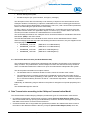
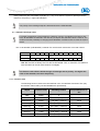
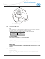
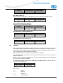
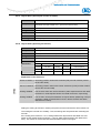
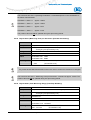
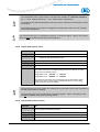
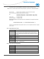
User manual
Magnetic absolute-value rotary encoders
with
- interface
WV58M, WH58M
Table of contents
1.
General remarks____________________________________________________4
1.1.
Definitions ___________________________________________________________ 4
1.2.
Documentation _______________________________________________________ 5
1.3.
Intended use _________________________________________________________ 5
2.
Product Family of Magnetic Angle Encoders ____________________________5
3.
General information on the CAN Bus___________________________________5
3.1.
CAN bus features _____________________________________________________ 6
3.2.
CANopen ____________________________________________________________ 6
3.3.
The Encoder Device Profile (CiA Draft Standard 406)________________________ 7
4.
Data Transmission according to the CANopen Communication Model _______7
4.1.
CANopen message setup ______________________________________________ 8
4.1.1
4.1.2
4.2.
Function code _______________________________________________________________ 8
Node number (Node ID) _______________________________________________________ 9
Transmission of process data___________________________________________ 9
4.2.1
4.2.2
Synchronous data transfer _____________________________________________________ 9
Asynchronous data transfer ___________________________________________________ 10
4.3.
Transmission of the SDO data (parameterization) _________________________ 10
4.4.
Emergency Service __________________________________________________ 12
4.5.
Network management Services (NMT) ___________________________________ 14
4.5.1
4.5.2
4.5.3
4.5.4
4.5.5
4.5.6
5.
Description of the NMT commands _____________________________________________ 14
Command byte _____________________________________________________________ 14
NMT status ________________________________________________________________ 14
The individual NMT states ____________________________________________________ 15
Status change ______________________________________________________________ 15
Heartbeat _________________________________________________________________ 16
Directory of objects ________________________________________________17
5.1.
Overview of objects __________________________________________________ 17
5.2.
Detailed description of objects _________________________________________ 19
5.2.1
5.2.2
5.2.3
5.2.4
5.2.5
5.2.6
5.2.7
5.2.8
5.2.9
5.2.10
5.2.11
5.2.12
5.2.13
Object 1000h (Device Type) ___________________________________________________ 19
Object 1001h (Error Register)__________________________________________________ 19
Object 1002h (Manufacturer Status Register) _____________________________________ 20
Object 1003h (Pre-defined Error Field)___________________________________________ 20
Object 1005h (COB ID SYNC message) _________________________________________ 21
Object 1008h (Manufacturer Device Name) _______________________________________ 21
Object 1009h (Manufacturer Hardware Version) ___________________________________ 21
Object 100Ah (Manufacturer Software Version) ____________________________________ 22
Object 1010h (Store Parameters) _______________________________________________ 22
Object 1011h (Load Default Parameters) _________________________________________ 23
Object 1014h (COB ID Emergency Object) _______________________________________ 24
Object 1017h (Producer Heartbeat Time)_________________________________________ 24
Object 1018h (Identity Object) _________________________________________________ 25
Date: 21.03.2007
Page 2 of 41
Item no. 83069
Revision status 78/07
5.2.14
5.2.15
5.2.16
5.2.17
5.2.18
5.2.19
5.2.20
5.2.21
5.2.22
5.2.23
5.2.24
5.2.25
5.2.26
5.2.27
5.2.28
5.2.29
5.2.30
5.2.31
5.2.32
5.2.33
5.2.34
5.2.35
5.2.36
5.2.37
5.2.38
5.2.39
6.
Object 1800h (Transmit PDO1 Parameter, asynchronous operation mode) ______________ 25
Object 1801h (Transmit PDO12 parameter, synchronous operation mode) ______________ 26
Object 1A00h (Transmit PDO1 Mapping Parameter) ________________________________ 27
Object 1A01h (Transmit PDO2 Mapping Parameter) ________________________________ 28
Object 2001h (Manufacturer Offset) _____________________________________________ 28
Object 2002h (Zeroing of encoder value) _________________________________________ 29
Object 2800h (Send repeat counter for PDO1) ____________________________________ 29
Object 2801h (Send repeat counter for PDO2) ____________________________________ 30
Object 6000h (Operating Parameters) ___________________________________________ 30
Object 6001h (Measuring Units per Revolution [Encoder Resolution]) __________________ 31
Object 6002h (Total Measuring Range [Total Step Number]) _________________________ 31
Object 6003h (Preset value) ___________________________________________________ 32
Object 6004h (Position value)__________________________________________________ 32
Object 6200h (Cycle Timer) ___________________________________________________ 33
Object 6500h (Operating Status) _______________________________________________ 33
Object 6501h (SingleTurn resolution) ____________________________________________ 34
Object 6502h (Number of distinguishable revolutions)_______________________________ 34
Object 6503h (Alarms) _______________________________________________________ 34
Object 6504h (Supported Alarms) ______________________________________________ 35
Object 6505h (Warnings) _____________________________________________________ 35
Object 6506h (Supported Warnings) ____________________________________________ 36
Object 6507h (Profile and Software Version) ______________________________________ 36
Object 6508h (Operating Time) ________________________________________________ 36
Object 6509h (Encoder Zeroing Value) __________________________________________ 37
Object 650Ah (Module Identification) ____________________________________________ 37
Object 650Bh (Serial Number) _________________________________________________ 38
Setting and diagnosing elements_____________________________________38
6.1.
Setting of the Node Identifier (Node ID) __________________________________ 38
6.2.
Setting the baud rate _________________________________________________ 39
6.3.
Diagnosis LEDs _____________________________________________________ 39
7.
Commissioning ___________________________________________________40
7.1.
Switching on the supply voltage________________________________________ 40
7.2.
Sending the position value ____________________________________________ 40
7.2.1.
7.2.2.
7.3.
Asynchronous (cyclic) transmission _____________________________________________ 40
Synchronous transmission ____________________________________________________ 41
Stopping Transmission of the Position Value _____________________________ 41
Date: 21.03.2007
Page 3 of 41
Item no. 83069
Revision status 78/07
1. General remarks
This user manual is valid with effect from firmware version 3.00! It describes the software, parameterization
and commissioning of the rotary encoder.
1.1. Definitions
This symbol precedes passages in the text that should be read particularly carefully to
ensure flawless use and to exclude dangers.
This symbol indicates important information for proper handling of the rotary encoder.
Disregard of these hints may result in failures of functioning of the rotary encoder or its
environment.
⇒
This symbol indicates instructions for actions.
CAL
CAN Application Layer. Application layer (layer 7) in the CAN communication model.
CAN
Controller Area Network
CiA
CAN in Automation. International Associatioon of Users and Producers of CAN products.
COB
Communication Object. Transport unit in the CAN network (CAN message). Data is sent
within a COB via the network.
COB ID
COB Identifier. Unambiguous identification of a CAN message The identifier determines
the priority of the COB in the network.
ID
Identifier, see COB ID
LSB
Least significant bit/byte
MSB
Most significant bit/byte
NMT
Network Management. Service element of CAL, responsible for initialization, configuration and error handling in the network.
PDO
Process Data Object. Object for exchanging process data.
RTR
Remote Transmission Request; data request telegram
SDO
Service Data Object; communication object that enables the master to access the directory of objects of a node.
SYNC
Figures
Date: 21.03.2007
Synchronization telegram. Bus stations respond to the SYNC command by sending their
process values.
if not explicitly stated otherwise, decimal values are given as figures without
an extension (e.g., 1234), binary values are marked with a b after the figure
(e.g., 10011b), hexadecimal values with an h (e.g., 280h).
Page 4 of 41
Item no. 83069
Revision status 78/07
1.2. Documentation
This user manual is valid for the absolute, magnetic angle encoders WV58M or WH58M, respectively, and is intended to give the necessary information for handling these instruments.
For information regarding guarantee, safety and mechanical mounting of the angle encoders
WV/WH58M please refer to the User information accompanying these encoders.
1.3. Intended use
The said angle encoders are high-precision measuring instruments. They serve exclusively for
sensing angle positions and revolutions, processing and providing measured values as electrical output signals for the slave unit. The angle encoders must be used exclusively for this purpose.
2. Product Family of Magnetic Angle Encoders
At present, the product family of magnetic, absolute angle encoders consists of the following 4 types:
§ 10-bit Singleturn (1024 steps/revolution)
§ 12-bit Singleturn (4096 steps/revolution),
§ 10+12-bit Multiturn (1024 steps/revolution, 4096 revolutions),
§ 12+12-bit Multiturn (4096 steps/revolution, 4096 revolutions),
They are available either in solid shaft or in (blind hole) hollow shaft design, standard size with a diameter of 58mm. Although designed with a bus interface, the angle encoders are very compact.
The angle encoders are available with the following interfaces:
§ SN3 (serial RS485 interface with SIKONETZ3 protocol)
§ SSI (synchronous serial interface)
§ PB (Profibus-DP interface)
§ CAN (CANopen interface)
Below, only the angle encoder WV/WH58M with CANopen interface will be described.
3. General information on the CAN Bus
Originally, the CAN bus (CAN: Controller Area Network) was developed by Bosch and Intel for fast and
low-cost data transmission in the car industry. Nowadays, the CAN bus is also used in industrial automation.
The CAN bus is a field bus (the standards are defined by the association CAN in Automation (CiA)),
which enables communication of devices, actuators and sensors of different manufacturers.
Date: 21.03.2007
Page 5 of 41
Item no. 83069
Revision status 78/07
3.1. CAN bus features
§
Bus medium is a shielded twisted-pair cable,
§
The CAN bus is a multi-master bus, i.e., several CAN stations can request the bus at the same
time. The message with the highest priority (determined by the identifier) prevails.
§
Data rate up to 1Mbit/s permissible (with 40m network range).
§
Closed network on both sides.
§
Theoretically, up to 127 stations possible on one bus; however, practically only up to 32 stations
due to the driver.
§
Message-oriented communication: The message is marked with message identification (identifier). By means of the identifier, all bus stations check whether the message is relevant for each
of them.
§
All bus stations receive each message at the same time. Therefore, synchronization is possible.
§
The identifier determines the priority of the message. The lower the value of the identifier, the
higher is the priority of the message. This enables fast transmission of important messages via
the bus.
§
High transmission safety thanks to various error identification mechanisms, which complement
each other.
§
Localization of faulty or disabled bus stations. The CAN protocol includes function monitoring of
bus stations. The functionality of the latter will be limited or disconnected from the network if
they are faulty.
3.2. CANopen
The CANopen profile was developed on the basis of the layer 7 specification CAL (CAN Application
Layer) under the direction of the Steinbeis Transferzentrum für Automatisierung (Transfer centre for
automation). Compared to CAL, only the functions suitable for this use are included in CANopen.
Thus, CANopen is a subset of CAL optimised for the application enabling a simplified system design as well as the use of simplified devices. CANopen has been optimised for fast data exchange
in real-time systems.
The organization CAN in Automation (CiA) is responsible for the applicable standards of the respective profiles
The angle encoder WV/WH58M with CANopen interface fulfils the conditions specified in the
“CANopen Application Layer and Communication Profile“ (CiA Draft Standard 301, version 4.02)
and in the “CANopen Device profile for encoders“ (CiA Draft Standard 406, version 3.1).
CANopen enables:
§
easy access to all device and communication parameters,
§
synchronization of various devices,
§
automatic configuration of networks
§
cyclic and event-triggered data traffic
CANopen consists of four communication objects (COB) with different features:
§
Process Data Objects (PDOs) for real-time data.
§
Service Data Objects (SDOs) for parameter and program transmission.
Date: 21.03.2007
Page 6 of 41
Item no. 83069
Revision status 78/07
§
Network Management (NMT.
§
Predefined objects (for synchronization, emergency message).
The description of the device functionality via an directory of objects is the central element of the
CANopen standard. The directory of objects is subdivided into an area containing general information on the device (device identification, manufacturer’s name, etc.) and communication parameters,
and an area describing the specific device functionality.
An entry (“object”) of the directory of objects is identified via a 16-bit index and an 8-bit sub-index.
By means of these entries, the “application objects” of a device (e.g., position value in the case of
encoders) are made accessible in a standardised form via the network.
The functionality and features of a CANopen device can be described as a standardised “Electronic
Data Sheet” (EDS) in the ASCII format.
The EDS files allocated to the individual encoder versions can be downloaded from the SIKO
GmbH homepage (www.siko.de) under the following file names. Moreover, they are supplied on the
accompanying CD:
§
Wx58MCAN_1012.eds
(EDS file for 10+12Bit Multiturn)
§
Wx58MCAN_1212.eds
(EDS file for 12+12Bit Multiturn)
§
Wx58MCAN_10ST.eds
(EDS file for 10Bit-Singleturn)
§
Wx58MCAN_12ST.eds
(EDS file for 12Bit-Singleturn)
3.3. The Encoder Device Profile (CiA Draft Standard 406)
This profile describes a manufacturer-independent and mandatory specification of the interface for
rotary encoders. The profile defines, which CANopen functions are used and how they should be
used. This standard enables the creation of an open and manufacturer-independent bus system.
The device profile is divided into two object classes:
§
The standard class C1 describes all basic functions, which the encoder must contain.
§
The extended class C2 contains a wide range of additional functions that must either be supported by these encoders (mandatory) or are optional. Thus, devices of the C2 class contain all
the C1 and C2 mandatory functions as well as – manufacturer-dependent – additional, optional
functions.
Additionally, an addressing range is defined in the profile for assignment of special proprietary functions.
The WV/WH58M supports class C2.
4. Data Transmission according to the CANopen Communication Model
The communication model underlying CANopen provides two types of communication mechanisms:
§ Unconfirmed transmission of data having a length of 4bytes (Process Data Objects, PDO). These
data is transmitted with high priority (low COB identifier). PDOs are broadcast messages and provide
their data to all receivers on the bus at the same time.
§ Confirmed transfer also of longer data sets (parameters) between two stations with direct access to
the entries of the addressed station’s directory of objects (Service Data Objects, SDO). As a rule,
Date: 21.03.2007
Page 7 of 41
Item no. 83069
Revision status 78/07
these parameters are transmitted acyclically (e.g., only once when the system is started) and have,
therefore, low priority (= high COB identifier).
The priority of the message objects is determined via the COB identifier.
4.1. CANopen message setup
For easier management of the identifiers, CANopen uses the “Pre-Defined Connection Set”
Here, all identifiers are defined in the directory of objects with standard values. However, the
customer has the possibility of changing these identifiers via SDO access to meet his requirements.
The 11-bit identifier (COB identifier) consists of a 4-bit function code and a 7-bit node number.
Bit no.
10
Type
9
8
7
6
5
Function code
Assignment
x
x
x
4
3
2
1
0
x
x
Node number (Node ID)
x
0
0
x
x
x
Hint: Bits 5 and 6 are always set to 0 with the WV/WH58. Thus, a maximum of 31 different
node numbers can be set (node number 0 is illegal!).
The function code informs about the type of message and its priority. The higher the
value of the identifier, the lower the priority.
4.1.1 Function code
The following function codes have been defined in the “Pre-defined Connection Set” (only
the function codes used by the WV/WH58M are represented):
Object
Function code
Resulting COB ID
assigned communication parameter for index
NMT
0000b
0
-
SYNC
0001b
128 (80h)
1005h
EMERGENCY
0001b
128 (80h) + Node ID
1014h
PDO1 (tx)
1
0011b
384 (180h) + Node ID
1800h
PDO2 (tx)
1
SDO (tx)
0101b
640 (280h) + Node ID
1801h
1
1011b
1408 (580h) + Node ID
1200h
1
1100b
1536 (600h) + Node ID
1200h
1110b
1792 (700h) + Node ID
1017h
SDO (rx)
HEARTBEAT
1
Date: 21.03.2007
(tx) and (rx) seen from the rotary encoder
Page 8 of 41
Item no. 83069
Revision status 78/07
4.1.2 Node number (Node ID)
The 7-bit node number is set via the 5 DIP switches on the hardware of the encoder. After
removing the screw cap on the encoder hood, this DIP switch can be accessed (see chapter
6.1, Setting the Node Identifier (Node ID), page 38).
The 5 DIP switches determine bits 0 to 4. Bits 5 and 6 have always the value 0 and cannot
be changed.
Node number 0 is reserved and must not be used by any node. Therefore, resulting node
numbers are in the range of 1 .. 31. With the WV/WH58M, the setting of the node number 0 on
the DIP switch is automatically assigned to node number 1! Any freshly set node number is
only taken over after the next reset/power-on of the encoder.
Ex works, the rotary encoder is delivered with node number 1.
4.2. Transmission of process data
Two PDO services, PDO1 (tx) and PDO2 (tx), are available. Any PDO transmission can be initiated
as a result of various events:
§
Asynchronous (event-triggered) via internal device timer or change of the position value.
§
Synchronous as a response to a SYNC telegram.
§
As a response to a RTR telegram.
Both PDOs provide the current position of the encoder and are determined via objects 1800h,
1801h, 1A00h, 1A01h, 2800h, 2801h and 6200h.
With the WV/WH58M, PDO1 is assigned to asynchronous and PDO2 to synchronous process data
transmission. As a standard, PDO2 is disabled after each power-on of the encoder and must be released on request via SDO.
Request of the position value via RTR telegram is also only possible via PDO2.
The PDO message is set up as follows:
COB ID
11-bit
Process data in binary code
Byte 0 (LSB)
PDO1:
180h+Node ID
Byte 1
Byte 2
Byte 3 (MSB)
Position value in two’s complement representation
PDO2:
280h+Node ID
4.2.1 Synchronous data transfer
To be able to send process data synchronously, a value between 1 and F0h (=240) must be
written in object 1801h, sub-index 2.
If the value is 3, the PDO2 is sent after every third SYNC telegram (with value 1 it is sent after every SYNC telegram), as long as a 0 is written in object 2801h. For example, if a 5 has
been written in there, the PDO2 is sent after every third telegram as above, but only 5 times
th
altogether. Accordingly, the 15 SYNC telegram is followed by the last PDO.
Date: 21.03.2007
Page 9 of 41
Item no. 83069
Revision status 78/07
The counter for the amount of PDOs to be transmitted is reset in case of position change or
by the NMT reset command; i.e., if the position does not change it will be sent 5 times. If the
position changes it will be sent 5 times again.
In synchronous operation, the PDO2 is requested by a master via the SYNC telegram
(SYNC-COB ID = 80h).
If the PDO2 is to be requested via an RTR telegram, then the value 253 (=FDh) must be
written in object 1801h, sub-index 2.
4.2.2 Asynchronous data transfer
If a PDO is to be sent cyclically, then the cycle time must be entered into object 1800h, subindex 5, in milliseconds. The PDO will not be sent if the value 0ms is written. The function is
disabled. The minimum value to be set is 1 (=1ms).
Object 2800h offers another possibility: Cyclic sending is as described above if the value is
0. If the value is 1, then cyclic checking occurs whether the position value has changed. If
not, nothing will be sent. For example, if the value is 4, the PDO1 will be sent four times with
every cycle if a change has occurred.
Sending the PDO1 due to a change in the position value works only when the timercontrolled transmission has been disabled, that means, when a 0 has been written in subindex 5, object 1800h.
4.3. Transmission of the SDO data (parameterization)
The directory of objects of the rotary encoder can be accessed via an SDO message. All device parameter are stored in this directory of objects under standardised addresses (indexes) and can be
written and read by means of SDOs. SDOs are exchanged between two stations using the request/response method.
Two SDO services are available:
§ SDO (tx) (encoder Æ master): 580h + Node ID
§ SDO (rx) (master Æ encoder): 600h + Node ID
The SDO identifiers cannot be changed!
SDO messages are set up as follows:
COB ID
Command
SDO +
Node ID
Byte 0
Index
Byte 1
(LSB)
Byte 2
(MSB)
Sub-index
Byte 3
Service data (parameters)
Byte 4
(LSB)
Byte 5
Byte 6
Byte 7
(MSB)
For the meaning of index, sub-index and data please refer to chapter 5, “Directory of objects.
Date: 21.03.2007
Page 10 of 41
Item no. 83069
Revision status 78/07
The command byte specifies the length of the service data (parameters). In the case of the
WV/WH58M the following command bytes are valid:
Command byte
Type
Function
23h
SDO (rx), Initiate Download
Request
Send parameter to rotary encoder (data length = 4bytes)
60h
SDO (tx), Initiate Download
Response
Acknowledgement of data acquisition to master
40h
SDO (rx), Initiate Upload Request
Request parameter from rotary
encoder
42h
SDO (tx), Initiate Upload Response
Parameter to master (data
length = 4bytes)
80h
SDO (tx), Abort Domain
Transfer
Rotary encoder reports error
code to master
§ An error message (command 80h) replaces the normal response in case of an error.
§ The error message includes communication protocol errors as well as directory of objects
access errors (e.g., Write attempt on Read-Only object, etc.).
The error codes are described in the CANopen profile (DS 301) or in the encoder profile (DSP 406),
respectively. The table below shows the error codes used with the WV/WH58M:
Error code
Description
06010000h
Wrong access to an object.
06010001h
Read access to Write-Only
06010002h
Write access to Read-Only.
06020000h
Object doesn’t exist in the directory of objects.
06040043h
General parameter incompatibility
06070010h
Wrong data type, incorrect data length.
06090011h
Sub-index does not exist
06090030h
Wrong value range of selected parameter.
06090036h
Maximum value smaller than minimum value.
08000020h
Parameters cannot be transmitted to application or stored.
08000022h
Parameters cannot be transmitted to application or stored due to the current
device status.
SDO examples:
Request of a value by a master from a slave Æ Operating Status (Object 6500h):
COB ID
Command
Index L
600h +
Node ID
40h
00h
Date: 21.03.2007
Index H Sub-index Data 0
65h
Page 11 of 41
00h
x
Item no. 83069
Data 1
Data 2
Data 3
x
x
x
Revision status 78/07
Response to the request by the slave
COB ID
Command
Index L
580h +
Node ID
42h
00h
Index H Sub-index Data 0
65h
00h
Data 1
Data 2
Data 3
b
c
d
Data 1
Data 2
Data 3
03h
00h
00h
Data 1
Data 2
Data 3
00h
00h
00h
a
Writing a value from master to a slave Æ object 1800, sub-index 5 (Event Timer):
COB ID
Command
Index L
600h +
Node ID
23h
00h
Index H Sub-index Data 0
18h
05h
E8h
Response from slave to writing the value:
COB ID
Command
Index L
600h +
Node ID
60h
00h
Index H Sub-index Data 0
18h
05h
00h
4.4. Emergency Service
Internal device errors or bus problems trigger an emergency message. The corresponding telegram
is set up as follows:
COB ID
80h +
Node ID
Byte 0
Byte 1
Error Code
Byte 2
Error
Register
Byte 3
Byte 4
Alarms (Object
6503h)
Byte 5
Byte 6
Warnings (Object
6505h)
Byte 7
00h
If the value “11h” has been written in the “Error Register”, then the meaning of bytes 3 – 6 in
the Emergency telegram changes. The value “11h” indicates errors that have occurred during data transmission to the CAN bus (see description “Error Codes”). The encoder has entered the “Error Passive” state .
If the interference load on the CAN bus decreases, then the encoder will return automatically
to the normal state called “Error Active”. If, however, the interference load continues to increase, then the encoder changes to the “Bus Off” state and performs a restart, which is
characterized by a “boot-up message” and an additional “Emergency-Message” (byte3 and
byte4 = 0).
Emergency message in case of bus errors:
COB-ID
80h +
Node-ID
Byte 0
Byte 1
Error Code
Byte 2
Byte 3
Byte 4
Byte 5
Byte 6
Byte 7
Error
Register
Transmit
Error
Counter
Receive
Error
Counter
00h
00h
00h
As with the SDO error messages, pre-defined error messages are assigned to the EMERGENCY
object as well. The WV/WH58M uses a subset of these error codes as described in the CAN Application Layer DS301. They are contained in the table below:
Date: 21.03.2007
Page 12 of 41
Item no. 83069
Revision status 78/07
Byte 0 .. Byte 1: Error Code
Error Codes Description
0000h
no error
8001h
CANbus communication error:
Æ Acknowledgement Error
8002h
CANbus communication error:
Æ Form Error
8003h
CANbus communication error:
Æ CRC Error
8004h
CANbus communication error:
Æ Stuff Error
8120h
encoder is in the Error Passive Mode
8140h
recovered from Bus Off
FF10h
encoder-specific error:
Æ communication with basic encoder card disabled
FF20h
encoder-specific error:
Æ battery warning; battery charge near lowest permissible limit
FF30h
encoder-specific error:
Æ battery discharged
FF40h
encoder-specific error:
Æ checksum error in communication with basic encoder card
FF50h
encoder-specific error:
Æ timeout error in communication with basic encoder card
Byte 2: Error Register
Bit no.
Description
0
set bit indicates general error condition; is set with every error occurring.
4
communication error; is set when a CANbus communication error occurs (acknowledgement, form, C, and stuff error).
Byte 3 .. Byte 4: Alarms
Bit no.
Description
0
position value invalid.
12
communication with basic encoder card disabled
13
timeout error in communication with basic card.
14
battery warning
15
battery alarm
Date: 21.03.2007
Page 13 of 41
Item no. 83069
Revision status 78/07
Byte 5 .. Byte 6: Warnings
Bit no.
Description
4
battery status critical
12
Faults in data traffic with basic encoder card (checksum error).
13
communication with basic encoder card was interrupted manually via DIP switch 1.
Byte 7: not used
4.5. Network management Services (NMT)
The network management can be subdivided into two groups:
§
NMT service for device control; serves for initialising, starting and stopping of the encoder,
§
NMT service connection monitoring (“Heartbeat”).
4.5.1
Description of the NMT commands
The commands are transmitted as unconfirmed objects (broadcast messages) and are set
up as follows:
COB-ID
Byte 1
Byte 2
0h
Command byte
Node number
(node ID)
The COB ID for NMT commands is always zero (highest priority). The node ID is transmitted
in byte 2 of the NMT command.
The node number corresponds with the node ID of the desired station. With node number =
0, all bus stations are addressed.
4.5.2
Command byte
Command
byte
4.5.3
Date: 21.03.2007
State transition (see
Description
Status diagram, fig. 1)
01h
Start_Remote_Node; change from state “PreOperational or “Stopped” to “Operational”
1
02h
Stop_Remote_Node; change to state “Stopped”
2
80h
Enter_PRE-OPERATIONAL_State; change to state
“Pre-Operational”
3
81h
Re-initialization of CAN parameters
4
82h
Reset of CAN card
5
NMT status
After initialising, the encoder is in the “Pre-Operational” state. SDO parameters can be read
and written in this state. To request PDOs, the encoder must first be switched to the “Operational” state.
Page 14 of 41
Item no. 83069
Revision status 78/07
Power on or Software Reset
Re-initialization
CAN card
5
Init
5
Initialization
CAN communication
5
4
BootUp Message
4
3
4
2
3
1
1
2
Fig. 1: CAN status diagram
4.5.4
The individual NMT states
Init:
After initialization, the encoder logs in at the CAN bus with a boot-up message. Afterwards,
the encoder changes automatically to the “Pre-operational” state.
The COB ID of the boot-up message is made up of 700h and the Node ID.
COB ID
Byte 0
700h + Node ID
00h
Pre-Operational Mode:
SDOs can be read and written in the Pre-Operational Mode.
Operational Mode:
In the Operational Mode state, the encoder sends the desired PDOs. Additionally, SDOs can
be read and written.
Stopped Mode:
Only NMT communication is enabled in the Stopped Mode. No SDO parameters can be read
or written.
4.5.5
Status change
Start Remote Node (1)
With the “Start_Remote_Node” command, the encoder is set to the “Operational Mode”
status.
Date: 21.03.2007
Page 15 of 41
Item no. 83069
Revision status 78/07
COB ID
Command byte
Node number
0h
1h
0h .. 1Fh (0 .. 31)
Stop Remote Node (2)
With the “Stop_Remote_Node” command, the encoder is set to the “Stopped” status.
COB ID
Command byte
Node number
0h
2h
0h .. 1Fh (0 .. 31)
Enter_PRE-OPERATIONAL-Mode (3)
Change to the “Pre-Operational” status.
COB ID
Command byte
Node number
0h
80h
0h .. 1Fh (0 .. 31)
Re-initialisation of CAN parameters (4)
COB ID
Command byte
Node number
0h
81h
0h .. 1Fh (0 .. 31)
Re-initialisation of the CAN card (5)
4.5.6
COB ID
Command byte
Node number
0h
82h
0h .. 1Fh (0 .. 31)
Heartbeat
There are two optional monitoring mechanisms intended for ensuring proper functioning of
the CANopen network nodes: Each network node can be monitored by a higher-order master via the so-called “Node Guard” or, alternatively, announce its ability to communicate by
cyclic sending of a so-called “Heartbeat” message.
With the WV/WH58M, the “Heartbeat” method is used exclusively.
This message can be received by one or several network subscribers and, thus, monitor the
assigned subscriber.
In object 1017h, “Producer Heartbeat Time”, the time of the heartbeat interval can be deposited. The value 0 disables heartbeat.
The heartbeat message consists of the COB ID and an additional byte. In this byte, the current NMT state is deposited.
COB ID
Byte 0
700h + Node ID
NMT status
NMT status:
Date: 21.03.2007
§ 0:
Boot-Up
§ 4:
Stopped
§ 5:
Operational
§ 127:
Pre-Operational
Page 16 of 41
Item no. 83069
Revision status 78/07
5. Directory of objects
In the directory of objects of a CANopen device, all features and parameters of the respective device are
deposited.
Specific parameters of the directory of objects are deposited in a power-failure-safe memory of
the encoder and are copied into the main memory during power-on or re-initialization.
The directory of objects is accessed via the SDO services described in chapter 4.3, “Transmission of the
SDO data (Parameterization)”.
The directory of objects is subdivided into three separate areas:
§ Standard objects applicable to all CANopen instruments, 1h .. 1FFFh, (CiA DS 301)
§ Manufacturer-specific objects, 2000h .. 5FFFh
§ Device-specific objects, 6000h .. BFFFh, (CiA DS 406)
The address (index) pointing to each entry in the directory of objects is also standardised in the profiles
except for the manufacturer-specific area. This fact ensures that all instruments always provide the functions described in the profile (standard and optional functions) under the same index. This is a precondition of an open system and of exchangeability of the instruments.
The entries of the directory of objects are addressed by a 16-bit index. Each index can be further subdivided by a sub-index.
5.1. Overview of objects
Index
Name
Description
1000h
Device Type
indicates the device profile and the encoder type
19
1001h
Error Register
indicates error states of the encoder
19
1002h
Manufacturer Status
Register
indicates the contents of the CAN bus-specific “TransmitErrorCounter” or “ReceiveErrorCounter”, respectively, and the firmware version of the basic card
20
1003h
Pre-Defined Error
Field
the object stores the 8 error states that have occurred last
20
1005h
COB ID SYNC message setting of the COB ID of the SYNC object.
21
1008h
Manufacturer Device
Name
short designation of the device type
21
1009h
Manufacturer Hardware Version
hardware version of the encoder
21
100Ah
Manufacturer Software Version
software version of the encoder
22
1010h
Store Parameters
the object indicates non-volatile storage of parameters by the encoder with no user input.
22
1011h
Restore Parameters
the object indicates that the encoder automatically
loads parameters from the non-volatile memory.
23
1014h
COB ID Emergency
Object
COB ID of the Emergency object
24
Date: 21.03.2007
Page 17 of 41
see page
Item no. 83069
Revision status 78/07
Index
Name
Description
1017h
Producer Heartbeat
Time
setting of the cycle time of the heartbeat timer
24
1018h
Identity Object
contains the manufacturer number assigned by CiA
25
1800h
Transmit PDO1
Communication Parameter
Transmit PDO for the asynchronous operation mode
(timer or position-value-controlled
25
1801h
Transmit PDO2
Communication Parameter
Transmit PDO for the synchronous operation mode,
including output of the position value via RTR
26
1A00h
Transmit PDO1 Mapping Parameter
27
1A01h
Transmit PDO2 Mapping Parameter
28
2001h
Manufacturer Offset
manufacturer-specific offset value (is added to the
position value encoder-internally)
28
2002h
Zero encoder
set position value to value 0 (condition: pre-set value 0)
29
2800h
Send repeat counter
for PDO1
indicates how often the PDO1 is sent
29
2801h
Send repeat counter
for PDO2
indicates how often the PDO2 is sent
30
6000h
Operating Parameters setting of sense of rotation and scaling function
30
6001h
Measuring units per
Revolution
parameterization of the resolution in steps / revolution of the encoder
31
6002h
Total measuring range
in measuring units
parameterization of the total measuring range of the
encoder
31
6003h
Preset Value
parameterization of a pre-set (calibration) value
32
6004h
Position Value
position value (offset with pre-set and manufacturer
offset value)
32
6200h
Cycle Timer PDO1
value in ms, identical with object 1800h, sub-index 5
33
6500h
Operating Status
indicates the sense of rotation and scaling function
currently set
33
6501h
Singleturn Resolution
indicates the maximum possible resolution in steps /
revolution
34
6502h
Number of distinindicates the maximum possible number of revoluguishable Revolutions tions
34
6503h
Alarms
indication of error states
34
6504h
Supported Alarms
indicates which alarm messages are supported
35
6505h
Warnings
indication of warnings
35
6506h
Supported Warnings
indicates which warnings are supported
36
6507h
Profile and Software
Version
indicates the version number of the device profile used
and the version number of the encoder’s firmware
36
6508h
Operating Time
outputs the value FFFFFFFFh (function is not yet
supported at present)
36
Date: 21.03.2007
Page 18 of 41
see page
Item no. 83069
Revision status 78/07
Index
Name
Description
6509h
Offset Value
corresponds with the encoder’s zero point value
37
650Ah
Module Identification
device-specific parameters (Manufacturer Offset,
Manufacturer min position value, Manufacturer max
position value) can be represented via sub-indexes
37
650Bh
Serial Number
outputs the value FFFFFFFFh (function is not yet
supported at present)
38
see page
5.2. Detailed description of objects
5.2.1 Object 1000h (Device Type)
Sub-index
00h
Description
Information on device type and device profile
Access
ro
Data type
UNSIGNED 32
EEPROM
no
Default
Multiturn:
00030196h
Singleturn:
00010196h
Data content
Device profile number
Encoder type
Byte 0
Byte 1
Byte 2
Byte 3
96h
01h
03h
00h
0196h (= 406):
CANopen Device Profile for Encoders, version 3.01
0003h:
Single-turn angle encoder, absolute, with battery-buffered electronic revolution
counter (multi-turn)
0001h:
Single-turn angle encoder, absolute
5.2.2 Object 1001h (Error Register)
Sub-index
00h
Description
device errors occurring are indicated here
Access
ro
Data type
UNSIGNED 8
EEPROM
no
Default
no
Data content
Bit
0
set bit indicates the occurrence of any error condition
4
set bit indicates communication error on the CAN bus (acknowledgement-, form-, CRC- and stuffbit)
1-3, 5-7
Date: 21.03.2007
Meaning
not used
Page 19 of 41
Item no. 83069
Revision status 78/07
5.2.3 Object 1002h (Manufacturer Status Register)
Sub-index
00h
Description
The counts of the registers “Transmit Error Counter” and “Receive Error Counter” can be read via this object.
The contents of these registers provide information on the transmission
faults present at the mounting site of the encoder.
Additionally, the version status of the basic card firmware is output.
Access
ro
Data type
UNSIGNED 32
EEPROM
no
Default (multi-turn encoder)
02070000h
Default (single-turn encoder) 02080000h
Data content
Byte 0
Byte 1
Byte 2
Byte 3
Receive Error
Counter
Transmit Error
Counter
Firmware status
basic card LOW
Firmware status
basic card HIGH
For details on the above-mentioned counters refer to the relevant CAN bus publications.
5.2.4 Object 1003h (Pre-defined Error Field)
Date: 21.03.2007
§
The object stores the 8 error states that have occurred last
§
the entry under sub-index 0 indicates the number of errors stored.
§
Each newly added error state is stored under sub-index 1. Previous error messages “slip” downward in their position by one digit.
§
The whole error list is deleted by writing the value 0 at sub-index 0.
§
The entries in the error list have the format described in chapter 4.4, Emergency Service.
Sub-index
00h
Description
number of error messages stored
Access
rw
Data type
UNSIGNED 8
EEPROM
no
Default
0
Value range
0–8
Sub-index
01h .. 08h
Description
error messages that occurred
Access
ro
Data type
UNSIGNED 32
EEPROM
no
Default
0
(recordable in the “Pre-Operational” and “Operational” states)
Page 20 of 41
Item no. 83069
Revision status 78/07
5.2.5 Object 1005h (COB ID SYNC message)
Sub-index
00h
Description
Defines the COB ID of the synchronization object (SYNC)
Access
rw
Data type
UNSIGNED 32
EEPROM
yes
Default
80h
Data content
(recordable in the “Pre-Operational” state only)
Bit 31:
not defined
Bit 30:
0:
encoder generates no SYNC message
1:
encodes generates SYNC messages
0:
11-bit identifier (CAN 2.0A)
1:
29-bit identifier (CAN 2.0B)
0:
if bit 29 = 0,
X:
if bit 29 = 1: bits 28 – 11 of the 29-bit SYNC-COB ID
X:
bits 10 – 0 of the SYNC-COB ID
Bit 29:
Bit 28..11
Bit 10.0.0
5.2.6 Object 1008h (Manufacturer Device Name)
Sub-index
00h
Description
short encoder designation in ASCII
Access
const
Data type
Visible_String
EEPROM
no
Default
W58M
Data content
Byte 0
Byte 1
Byte 2
Byte 3
57h (‚W‘)
35h (‚5‘)
38h (‚8‘)
4Dh (‚M‘)
5.2.7 Object 1009h (Manufacturer Hardware Version)
Sub-index
00h
Description
hardware version in ASCII
Access
const
Data type
Visible_String
EEPROM
no
Default
“1.00“
Data content
Date: 21.03.2007
Byte 0
Byte 1
Byte 2
Byte 3
31h (‚1‘)
2Ehh (‚.‘)
30h (‚0‘)
30h (‚0‘)
Page 21 of 41
Item no. 83069
Revision status 78/07
5.2.8 Object 100Ah (Manufacturer Software Version)
Sub-index
00h
Description
software version in ASCII
Access
const
Data type
Visible_String
EEPROM
no
Default
“3.00“
Data content
Byte 0
Byte 1
Byte 2
Byte 3
33h (‚3‘)
2Eh (‚.‘)
30h (‚0‘)
30h (‚0‘)
5.2.9 Object 1010h (Store Parameters)
This object serves exclusively for information that the encoder automatically stores specific
parameters in the EEPROM. The “Store Parameter” command is not required for this purpose!
Sub-index
00h
Description
describes the number of entries present in sub-index 1.
Access
ro
Data type
UNSIGNED 8
EEPROM
no
Default
1h
Sub-index
01h
Description
describes the behaviour of the encoder, how parameters are stored in the
EEPROM.
Access
ro
Data type
UNSIGNED 32
EEPROM
no
Default
2h
Data content
Bit 31 -2
0
Bit 1:
0:
encoder does not store parameters automatically
1:
encoder stores parameters automatically following
write access to relevant object
0:
encoder does not store parameter by command
1:
encoder stores parameter after command
Bit 0:
Date: 21.03.2007
Page 22 of 41
Item no. 83069
Revision status 78/07
The following table represents the parameters stored in the EEPROM:
Object
Sub-index
Description
Default value
1005h
0h
SYNC-ID
80h
1014h
0h
EMCY-ID
80h + Node ID
1017h
0h
Producer Heartbeat Time
0h
1800h
1h
PDO1-ID
40000180h + Node ID
1800h
2h
PDO1 Transmission Type
FEh (= 254)
1800h
5h
PDO1 Event Timer
0h
1801h
1h
PDO2-ID
80000280h + Node ID
1801h
2h
PDO2 Transmission Type
1h
2001h
0h
Manufacturer Offset
0h
2800h
0h
PDO1 send repeat counter
0h
2801h
0h
PDO1 send repeat counter
0h
6000h
0h
Operating Status
0h
6001h
0h
Encoder resolution
10-bit encoder
1024
12-bit encoder
4096
10-bit encoder
4194304
12-bit encoder
16777216
6002h
0h
Total measurement range
6003h
0h
Preset value
0h
6200h
0h
PDO1 Event Timer
see object 1800-5
5.2.10 Object 1011h (Load Default Parameters)
This object serves for setting the encoder to its default values (see 5.2.9). To be safeguarded against unintended loading of the default values, the string “load” must be written in
sub-index 1h.
COB ID
Command
Index
Low
Index
High
Sub-index
Data 0
(LSB)
Data 1
Data 2
Data 3
(MSB)
600h +
Node ID
23h
11h
10h
01h
‘l‘ (6Ch)
‘o‘ (6Fh)
‘a‘ (61h)
‘d‘ (64h)
A read access to the respective sub-indexes results in the values represented below:
Date: 21.03.2007
Sub-index
00h
Description
indicates the largest supported sub-index
Access
ro
Data type
UNSIGNED 8
EEPROM
no
Default
1h
Page 23 of 41
Item no. 83069
Revision status 78/07
Sub-index
01h
Description
all default values are loaded
Access
rw
Data type
UNSIGNED 32
EEPROM
no
Default
0h
Data content
(recordable in the “Pre-Operational” and “Operational” states)
Bit 31 -1
0
Bit 0:
0:
encoder does not permit loading of default parameters.
1:
encoder permits loading of default parameters.
5.2.11 Object 1014h (COB ID Emergency Object)
Sub-index
00h
Description
defines the COB ID of the Emergency object (EMCY)
Access
rw
Data type
UNSIGNED 32
EEPROM
yes
Default
80h + Node ID
Data content
(recordable in the “Pre-Operational” state only)
Bit 31:
0:
EMCY object exists / is valid
1:
EMCY object does not exists / is invalid
Bit 30:
always 0
Bit 29:
0:
11-bit identifier (CAN 2.0A)
1:
29-bit identifier (CAN 2.0B)
0:
if bit 29 = 0,
X:
if bit 29 = 1: bits 28 -11 of the 29-bit EMCY-COB ID
X:
bits 10 – 0 of the EMCY-COB ID
Bit 28..11
Bit 10.0.0
5.2.12 Object 1017h (Producer Heartbeat Time)
Sub-index
00h
Description
defines the cycle time of the heartbeat monitoring service
Access
rw
Data type
UNSIGNED 16
EEPROM
yes
Default
0h
Value range
10 .. 65535 (Ah .. FFFFh); the numerical value corresponds with a multiple of
1ms.
(recordable in the “Pre-Operational” and “Operational” states)
The service is disabled by writing the value 0.
The writing of values in the range of 1 .. 9 trigger an error message!
Date: 21.03.2007
Page 24 of 41
Item no. 83069
Revision status 78/07
5.2.13 Object 1018h (Identity Object)
Sub-index
00h
Description
number of entries
Access
ro
Data type
UNSIGNED 8
EEPROM
no
Default
2h
Sub-index
01h
Description
The manufacturer identification number (vendor ID) for the company SIKO
GmbH allocated by the CiA (see www.can-cia.org)
Access
ro
Data type
UNSIGNED 32
EEPROM
no
Default
195h
Sub-index
02h
Description
indicates the encoder version in ASCII.
Access
ro
Data type
UNSIGNED 32
EEPROM
no
Default
10+12-bit version:
“1012“
12+12-bit version:
“1212“
10-bit SingleTurn
“10ST“
12-bit SingleTurn
“12ST“
Byte 0
Byte 1
Byte 2
Byte 3
32h (‘2‘)
31h (‘1‘)
32h (‘2‘)
31h (‘1‘)
Example: 10+12 bits version
32h (‘2’)
31h (‘1’)
30h (‘0’)
31h (‘1’)
Example: 10 bits single-turn
54h (‚T’)
53h (‚S’)
30h (‘0’)
31h (‘1’)
Example: 12 bits single-turn
54h (‚T’)
53h (‚S’)
32h (‘2’)
31h (‘1’)
Data content (example:
12+12 bits version):
5.2.14 Object 1800h (Transmit PDO1 Parameter, asynchronous operation mode)
Date: 21.03.2007
Sub-index
00h
Description
largest subindex supported
Access
ro
Data type
UNSIGNED 8
EEPROM
no
Default
5h
Page 25 of 41
Item no. 83069
Revision status 78/07
Sub-index
01h
Description
COB ID of the PDO1
Access
rw
Data type
UNSIGNED 32
EEPROM
yes
Default
40000180h + Node ID
Sub-index
02h
Description
Transmission Type
Access
ro
Data type
UNSIGNED 8
EEPROM
no
Default
FEh (254)
Sub-index
03h (is not used, access attempt generates error message)
Sub-index
04h (is not used, access attempt generates error message)
Sub-index
05h
Description
Event Timer
Access
rw
Data type
UNSIGNED 16
EEPROM
yes
Value range
1 .. 65535 (1h .. FFFFh); the numerical value corresponds with a multiple of
1ms.
(recordable in the “Pre-Operational” state only)
bit30 = 1: RTR for this PDO not released, bit is
always set
PDO has asynchronous characteristics (PDOs are sent depending on the “Event Timer”). This value cannot be changed!
(recordable in the “Pre-Operational” state only)
The service is disabled by writing the value 0.
The content of this object is identical with object 6200h.
5.2.15 Object 1801h (Transmit PDO12 parameter, synchronous operation mode)
Date: 21.03.2007
Sub-index
00h
Description
largest subindex supported
Access
ro
Data type
UNSIGNED 8
EEPROM
no
Default
5h
Page 26 of 41
Item no. 83069
Revision status 78/07
Sub-index
01h
Description
COB ID of the PDO2
Access
rw
Data type
UNSIGNED 32
EEPROM
yes
Default
80000280h + Node ID
Sub-index
02h
Description
Transmission Type
Access
rw
Data type
UNSIGNED 8
EEPROM
yes
Default
1h
Value range
1h .. n .. F0h (240)
The PDO is sent after every nth SYNC command, also
depending on the value in object 2801h.
FDh (253):
encoder responds to RTR request.
(recordable in the “Pre-Operational” state only)
bit31 = 1: PDO2 is always disabled after PowerOn (Init); must be explicitly enabled via SDO service.
(recordable in the “Pre-Operational” state only)
PDO has synchronous characteristics;
Sub-index
03h (is not used, access attempt generates error message)
Sub-index
04h (is not used, access attempt generates error message)
Sub-index
05h (is not used, access attempt generates error message)
5.2.16 Object 1A00h (Transmit PDO1 Mapping Parameter)
Date: 21.03.2007
Sub-index
00h
Description
number of objects mapped
Access
ro
Data type
UNSIGNED 8
EEPROM
no
Default
1h
Sub-index
01h
Description
writes in the content of the PDO1 message
Access
ro
Data type
UNSIGNED 32
EEPROM
no
Default
60040020h
Page 27 of 41
Item no. 83069
Revision status 78/07
5.2.17 Object 1A01h (Transmit PDO2 Mapping Parameter)
Sub-index
00h
Description
number of objects mapped
Access
ro
Data type
UNSIGNED 8
EEPROM
no
Default
1h
Sub-index
01h
Description
Writes in the content of the PDO2 message
Access
ro
Data type
UNSIGNED 32
EEPROM
no
Default
60040020h
5.2.18 Object 2001h (Manufacturer Offset)
Sub-index
00h
Description
The offset enables the shifting of the scaled value range. The offset value is
added to the position value in the encoder. Positive as well as negative values
are permitted. NOTE: This object is not available for the single-turn versions
of the WV/WH58M!
Access
rw
Data type
SIGNED 32
EEPROM
yes
Default
0h
Value range
The minimum or maximum values to be entered depend on the values entered in object 650Ah, sub-index 2 or sub-index 3, respectively. The latter
depend on the parameterised value of the total step number:
(recordable in the “Pre-Operational” and “Operational“ states if the
“Scaling bit” [see object 6000h] is set)
lower_limit = - 1/2 total step number,
upper_limit = 1/2 total step number – 1
lower_limit < offset < upper_limit
The execution time of the “Manufacturer Offset“ command is approx. 36ms. The position value
will not be updated during this processing period!
Date: 21.03.2007
Page 28 of 41
Item no. 83069
Revision status 78/07
5.2.19 Object 2002h (Zeroing of encoder value)
Sub-index
00h
Description
This object enables “zeroing” of the encoder value, i.e., setting the position
value to 0 (condition: pre-set value = 0).
Access
rw
Data type
UNSIGNED 8
EEPROM
no
Default
no
Value range
0 .. 1; writing the value 1 on sub-index 0 sets the position value to 0. Renewed
zeroing is only enabled after writing a 0 before.
(recordable in the “Pre-operational” and “Operational” states)
Example:
COB ID
Command
Index
Low
Index
High
Sub-index
Data 0
(LSB)
600h +
Node ID
23h
02h
20h
00h
01h
Data 1 Data 2
00h
Data 3
(MSB)
00h
00h
Subsequently, the following command telegram must be sent:
COB-ID
Command
Index
Low
Index
High
Sub-index
Data 0
(LSB)
600h+
Node ID
23h
02h
20h
00h
00h
Data 1 Data 2
00h
Data 3
(MSB)
00h
00h
The execution time of the “Zeroing command” is approx. 40ms. The position value will not be
updated during this processing period!
5.2.20 Object 2800h (Send repeat counter for PDO1)
Date: 21.03.2007
Sub-index
00h
Description
The value of the send repeat counter for PDO1 determines how often this
PDO will be sent (see chapter 4.2, asynchronous data transfer)
Access
rw
Data type
UNSIGNED 8
EEPROM
yes
Default
0h
Value range
0 .. 100 (64h)
(recordable in the “Pre-operational” and “Operational” states)
Value = 0: Repeat counter is switched off
Page 29 of 41
Item no. 83069
Revision status 78/07
5.2.21 Object 2801h (Send repeat counter for PDO2)
Sub-index
00h
Description
The value of the send repeat counter for PDO2 determines how often this
PDO will be sent (see chapter 4.2.1, synchronous data transfer)
Access
rw
Data type
UNSIGNED 8
EEPROM
yes
Default
0h
Value range
0 .. 100 (64h)
(recordable in the “Pre-operational” and “Operational” states)
Value = 0: Repeat counter is switched off
5.2.22 Object 6000h (Operating Parameters)
Sub-index
00h
Description
This object influences the encoder’s code sequence and the scaling function.
Access
rw
Data type
UNSIGNED 16
EEPROM
yes
Default
0h
(recordable in the “Pre-operational” and “Operational” states)
Bit definition
Bit 14 .. Bit 3:
Bit 2:
Bit 1:
Bit 0:
Function
not used
Scaling
not used
Code sequence
Bit = 0
-
disabled
-
Sense of rot. I (CW)
Bit = 1
-
enabled
-
Sense of rot. E (CCW)
Explanation of the functions:
Sense of rotation I: ascending position values with clockwise (CW) encoder rotation (look at
the encoder shaft)
Sense of rotation E: ascending position values with counter-clockwise (CCW) encoder rotation
(look at the encoder shaft)
Scaling disabled:
The encoder works with its full resolution (1024 steps/revolution and 4096
revolutions or 4096 steps/revolution and 4096 revolutions, respectively)
Scaling enabled:
The encoder can be parameterised via objects 6001h (Measuring units per
revolution), 6002h (Total Measuring range), 6003h (Preset) and 2001h
(Manufacturer Offset).
Setting the scaling bit results in resetting the preset and the manufacturer offset values to 0.
The scaling bit is stored non-volatilely. Thus, all settings are still present after restarting the
encoder.
If the scaling bit is reset from 1 to 0, settings made with object 6001h and 6002h are overwritten by the default values (resolution = 1024 or 4096 steps/revolution and 4096 revolutions). The values for Preset and ManufacturerOfffset remain unchanged.
Date: 21.03.2007
Page 30 of 41
Item no. 83069
Revision status 78/07
The execution time of the “Operating Parameters” command depends on the combination of
the above-mentioned bits:
write Bit0 = 0, Bit2 = 0:
approx. 190ms
write Bit0 = 1, Bit2 = 0:
approx. 190ms
write Bit0 = 0, Bit2 = 1:
approx. 77ms
write Bit0 = 1, Bit2 = 1:
approx. 77ms
The position value will not be updated during this processing period!
5.2.23 Object 6001h (Measuring Units per Revolution [Encoder Resolution])
Sub-index
00h
Description
This parameter sets the desired resolution per revolution.
Access
rw
Data type
UNSIGNED 32
EEPROM
yes
Default
WV/WH58M-10bit:
1024
WV/WH58M-12bit:
4096
1 .. 1024
(WV/WH58M-10-bit)
1 .. 4096
(WV/WH58M-12-bit)
Value range
(recordable in “Pre-operational” and “Operational” states, if the
“Scaling bit” [see object 6000h] is set)
Any Preset and/or ManufacturerOffset values are reset to 0 when the resolution is changed!
The execution time of the “Measuring Units per Revolution“ command is approx. 160ms. The
position value will not be updated during this processing period!
5.2.24 Object 6002h (Total Measuring Range [Total Step Number])
Sub-index
00h
Description
This parameter sets the total number of measuring steps.
Access
rw
Data type
UNSIGNED 32
EEPROM
yes
Default
WV/WH58M-10-bit: 4194304
(recordable in “Pre-operational” and “Operational” states, if the
“Scaling bit” [see object 6000h] is set)
WV/WH58M-12-bit: 16777216
Value range
Date: 21.03.2007
4096 .. 4194304
(WV/WH58M-10-bit)
4096 .. 16777216
(WV/WH58M-12-bit)
Page 31 of 41
Item no. 83069
Revision status 78/07
X
The configurable value “Total of steps” must meet the condition 2 * Encoder resolution
(X = 1...12 for 12bit encoder and 1...10 for 10bit encoder, respectively).
Any Preset and/or ManufacturerOffset values are reset to 0 when the total number of steps
is changed!
Any attempt to write on this object in a SingleTurn encoder will result in an error message
(error code: 06040043h).
The execution time of the “Total Measuring Range” command is approx. 160ms. The position
value will not be updated during this processing period!
5.2.25 Object 6003h (Preset value)
Sub-index
00h
Description
The position value of the encoder is set to this preset value.
Access
rw
Data type
SIGNED 32
EEPROM
yes
Default
0h
Value range
The value range of the preset value depends on the settings made with objects 6001h and 6002. In the default setting of these two objects, the value
range covers the following range:
(recordable in “Pre-operational” and “Operational” states, if the “
Scaling bit” [see object 6000h] is set)
WV/WH58M-10-bit: -2097152 .. 0 .. +2097151
WV/WH58M-12-bit: -8388608 .. 0 .. +8388607
The maximum value range to be represented can be read with the object
650Ah, sub-index 2 and sub-index 3 and depends always on the settings
made with objects 6100h and 6002h!
The preset value is reset to 0 when the scaling bit is set and when the encoder resolution or
the total step number is changed.
The execution time of the “Preset Value” command is approx. 160ms. The position value
will not be updated during this processing period!
5.2.26 Object 6004h (Position value)
Date: 21.03.2007
Sub-index
00h
Description
This object provides the position value of the encoder offset with the scaling
factors, preset and ManufacturerOffset.
Access
ro
Data type
SIGNED 32
EEPROM
no
Page 32 of 41
Item no. 83069
Revision status 78/07
The position value of the WV/WH58M is calculated by using the following formula:
Position value = (encoder value-encoder zeroing value)*RF + preset value + ManufacturerOffset
Encoder value:
absolute value calculated by the encoder sensor system,
Encod. zeroing value: absolute value at the time of zeroing,
RF:
Calculation (scaling) factor = encoder resolution / 1024, (10-bit),
Calculation (scaling) factor = encoder resolution / 4096, (12-bit),
Preset value:
see Object 6300h
ManufacturerOffset:
see Object 2100h
With the WV/WH58M, the total measuring range is subdivided into a negative and positive
value range:
-1/2 total measuring range .. 0 .. +1/2 (total measuring range – 1)
Therefore, the representation of the position value is in the 2-complement format in a signed
32-bit number.
5.2.27 Object 6200h (Cycle Timer)
Sub-index
00h
Description
Defines the cycle time with which the PDO1 is output. The value is fixedlinked (identical) with the value indicated under object 1800h, sub-index 5.
The timer-controlled output is activated as soon as a cycle time was parameterised within the value range and the encoder switched over to the Operational Mode.
Access
rw
Data type
UNSIGNED 16
EEPROM
no
Default
0h
Value range
0:
Cycle timer is disabled,
1 .. 65535:
Cycle time in ms
(recordable in the “Pre-operational” and “Operational” states)
5.2.28 Object 6500h (Operating Status)
Date: 21.03.2007
Sub-index
00h
Description
The object indicates the settings programmed with object 6000h.
Access
ro
Data type
UNSIGNED 16
EEPROM
yes
Default
no
Bit definition
see Object 6000h
Page 33 of 41
Item no. 83069
Revision status 78/07
5.2.29 Object 6501h (SingleTurn resolution)
Sub-index
00h
Description
The object indicates the maximum possible encoder resolution.
Access
ro
Data type
UNSIGNED 32
EEPROM
no
Default
WV/WH58M (10+12-bit):
1024
WV/WH58M (10-bit ST):
1024
WV/WH58M (12+12-bit):
4096
WV/WH58M (12-bit ST):
4096
5.2.30 Object 6502h (Number of distinguishable revolutions)
Sub-index
00h
Description
The object indicates the maximum possible number of encoder revolutions.
Access
ro
Data type
UNSIGNED 16
EEPROM
no
Default
4096
5.2.31 Object 6503h (Alarms)
Sub-index
00h
Description
In addition to the errors reported via the emergency messages, this object
provides further, encoder-specific error messages. In the case of an error, the
associated bit is set to 1.
Access
ro
Data type
UNSIGNED 16
EEPROM
no
Default
0h
Bit definition:
Date: 21.03.2007
Bit
Function
Value = 0
Value = 1
0
position error
no error
position value invalid
1 .. 11
not used
-
-
12
connection with basic card connection established
13
timeout error in connection
to basic card
no fault
connection failure
14
battery warning
battery voltage OK
battery voltage near lowest
tolerable value
15
battery error
battery OK or still in tolerable range
battery discharged
Page 34 of 41
no basic card recognised
Item no. 83069
Revision status 78/07
5.2.32 Object 6504h (Supported Alarms)
Sub-index
00h
Description
The object indicates which alarm messages are supported.
Access
ro
Data type
UNSIGNED 16
EEPROM
no
Default
F001h
Bit 0:
Position error
Bit 12:
Connection with basic card
Bit 13:
Communication error with basic card (timeout)
Bit 14:
Battery warning
Bit 15:
Battery alarm
5.2.33 Object 6505h (Warnings)
Sub-index
00h
Description
Warnings indicate that tolerances of internal encoder parameters have been
exceeded. However, unlike with alarm messages, the position value can be
valid in case of a warning.
Access
ro
Data type
UNSIGNED 16
EEPROM
no
Default
0h
Bit definition:
Date: 21.03.2007
Bit
Function
Value = 0
Value = 1
0 .. 3
not used
-
-
4
battery warning
battery voltage OK
battery voltage near
lowest tolerable value
5 .. 11
not used
-
-
12
faults in data traffic with
the basic card
no faults
checksum error occurred
13
switch position of DIP
switch 1
switch is at OFF
switch is at ON; communication with basic
card was interrupted
manually
14, 15
not used
-
-
Page 35 of 41
Item no. 83069
Revision status 78/07
5.2.34 Object 6506h (Supported Warnings)
Sub-index
00h
Description
The object indicates which warnings are supported.
Access
ro
Data type
UNSIGNED 16
EEPROM
no
Default
3010h
Bit 4:
Battery warning is supported
Bit 12:
Communication warning (checksum error)
Bit 13:
State of DIP switch 1
5.2.35 Object 6507h (Profile and Software Version)
Sub-index
00h
Description
The object indicates the encoder profile used (CANopen Device profile for
encoders) and the version number of the firmware state.
Access
ro
Data type
UNSIGNED 32
EEPROM
no
Default
03000301h
Data content:
Profile Version
Firmware Version
Byte 0 (Low)
Byte 1 (High)
Byte 2 (Low)
Byte 3 (High)
01h
03h
00h
03h
5.2.36 Object 6508h (Operating Time)
Date: 21.03.2007
Sub-index
00h
Description
Operation time counter (not implemented in the encoder)
Access
ro
Data type
UNSIGNED 32
EEPROM
no
Default
FFFFFFFFh (shows that the function is not supported)
Page 36 of 41
Item no. 83069
Revision status 78/07
5.2.37 Object 6509h (Encoder Zeroing Value)
Sub-index
00h
Description
The difference between encoder value and the position value scaled and offset with preset and/or ManufacturerOffset is output via this object.
Access
ro
Data type
SIGNED 32
EEPROM
yes
(Position value - Preset value - ManufacturerOffset)
Encoder zeroing value = encoder value -
Scaling factor
5.2.38 Object 650Ah (Module Identification)
The Manufacturer Offset value (sub-index 1), the smallest (sub-index 2) and the largest (sub-index 3)
position value that can be displayed can be read out via this object.
Date: 21.03.2007
Sub-index
00h
Description
contains the number of additional sub-indexes.
Access
ro
Data type
UNSIGNED 8
EEPROM
no
Default
3h
Sub-index
01h
Description
manufacturer-specific offset value (is added to the position value )
Access
ro
Data type
SIGNED 32
EEPROM
yes
Default
0h
Sub-index
02h
Description
Minimum position value that can be displayed (is influenced by the scaling
objects 6001h and 6002h).
Access
ro
Data type
SIGNED 32
EEPROM
no
Default
WV/WH58M (10+12-bit):
-2097152
WV/WH58M (10-bit ST):
0
WV/WH58M (12+12-bit):
-8388608
WV/WH58M (12-bit ST):
0
Page 37 of 41
Item no. 83069
Revision status 78/07
Sub-index
03h
Description
Maximum position value that can be displayed (is influenced by the scaling
objects 6001h and 6002h).
Access
ro
Data type
SIGNED 32
EEPROM
no
Default
WV/WH58M (10+12-bit):
2097151
WV/WH58M (10-bit ST):
1024
WV/WH58M (12+12-bit):
8388607
WV/WH58M (1-bBit ST):
4096
5.2.39 Object 650Bh (Serial Number)
Sub-index
00h
Description
Provides the serial number of the encoder (not supported with the WV/WH58M).
Access
ro
Data type
UNSIGNED 32
EEPROM
no
Default
FFFFFFFFh (function is not implemented)
6. Setting and diagnosing elements
6.1. Setting of the Node Identifier (Node ID)
After removing the screw cap on the encoder hood, an 8-pin DIP
switch as well as two diagnosis LEDs (yellow and green) are visible.
Switches 4 to 8 serve for setting the Node Identifier. The adjustable
range is between 1 and 31. Although switches 4 to 8 can be set to
ON, the setting is converted to Node ID 1 encoder-internally since
the identifier 0 is illegal!
The Node ID via switches 4 to 8 is encoded in the binary format.
Fig. 2: DIP switches and diagnosis LEDs
This is illustrated in the following table:
Switch 4
Switch 5
Switch 6
Switch 7
Switch 8
Node ID set
ON
ON
ON
ON
ON
1 (!)
ON
ON
ON
ON
OFF
1
ON
ON
ON
OFF
ON
2
ON
ON
ON
OFF
OFF
3
Date: 21.03.2007
Page 38 of 41
Item no. 83069
Revision status 78/07
Switch 4
Switch 5
Switch 6
Switch 7
Switch 8
Node ID set
:
:
:
:
:
:
OFF
OFF
OFF
ON
OFF
29
OFF
OFF
OFF
OFF
ON
30
OFF
OFF
OFF
OFF
OFF
31
The DIP-switch settings are only read when the encoder is started (power-on or during new initialization via an NMT command). Changing the switch position during operation of the encoder
has no effect. (Exception: DIP switch 1)
The ex works standard setting is Node ID 1 (DIP switch 8 = OFF).
6.2. Setting the baud rate
The CAN baud rate is set via DIP switches 2 and 3. Four different baud rates can be selected. The
following table shows the allocation:
Switch 2
Switch 3
Baudrate
ON
ON
125 Kbit/s
ON
OFF
250 Kbit/s
OFF
ON
500 Kbit/s
OFF
OFF
1000 Kbit/s
The DIP-switch settings are only read when the encoder is started (power-on or during new initialization via an NMT command). Changing the switch position during operation of the encoder
has no effect. (Exception: DIP switch 1)
The ex works standard setting is baud rate 125 Kbit/s.
DIP switch 1 is exclusively intended for service purposes and must remain at the ON position.
6.3. Diagnosis LEDs
Beside the DIP switch there is each a green and yellow LED. They serve for signalling different
operational states:
Power (green)
Status (yellow)
Date: 21.03.2007
LED
Meaning
OFF
voltage supply missing
ON
voltage supply is OK
blinking (pulse duty factor 1:4)
encoder is in the Pre-Operational Mode
ON
encoder is in the Operational Mode
fast blinking (pulse duty factor 1:1)
encoder is in the Stopped Mode
Page 39 of 41
Item no. 83069
Revision status 78/07
7. Commissioning
Prior to commissioning of the encoder the following work should be performed:
-
Setting of the Node ID (must be present in the system only once),
-
setting of the CAN baud rate valid for the system,
-
correct connection of the supply and bus lines
7.1. Switching on the supply voltage
After switching on the supply voltage, the encoder initialises as indicated by blinking of the yellow
LED twice (only visible after the screw plug on the encoder hood has been removed).
After completing the initialization procedure, the encoder sends a specific NMT command, the
Boot-Up Message, to inform the system about the presence of the encoder. During initialization,
the parameters of the directory of objects are loaded from the non-volatile memory to the main
memory of the controller.
If the encoder has not been programmed yet, all parameters are set to their default values, otherwise the encoder operates with the latest parameterised data.
The encoder is now in the Pre-Operational Mode. In this state, the encoder can be parameterised
via SDO commands in accordance with the requirements of the application. This applies particularly
to the way the encoder makes available its position values to the system (asynchronous or synchronous data transmission)
NOTE: If the numerical value 7FFFFFFFh is read out as the position value, this indicates
that the encoder-internal CAN controller was unable to establish the connection to the
basic encoder card! Possible causes are: 1) the DIP switch 1 (see figure 2, chapter 6.1) is
not at the ON position or 2) contact problems of this switch prevent communication of
the CAN controller with the basic card.
7.2. Sending the position value
Before the encoder is able to send its position value, the encoder must be switched to the Operational Mode via the Node Start NMT command.
COB ID
Command byte
Node number
0h
1h
0h .. 1Fh (0 .. 31)
If the Node ID of the encoder is specified, then this encoder only will start. If the value 0 is transmitted for the node number, then all devices connected to the bus will start.
Now the encoder can transmit its position value as specified via PDO1 or PDO2, respectively.
7.2.1.
Asynchronous (cyclic) transmission
The PDO1 is responsible for this type of transmission. The position value is sent cyclically in
accordance with the time parameterised in object 1800h, sub-index 5.
Date: 21.03.2007
Page 40 of 41
Item no. 83069
Revision status 78/07
Object 2800h offers another possibility: If this object is parameterised with the value 1, then
the position value is sent once with every change of the same. The value 3 will cause the
position value to be sent three times with each change.
7.2.2.
Synchronous transmission
To enable synchronous transmission of the position value, the PDO2 must first be enabled
(set bit31 of the COB ID PDO2 to 0). Furthermore, a value between 1 and 240 (= F0h) must
be written in object 1801h, sub-index 2.
For example, if the value is 3, the PDO2 is sent after every third SYNC telegram (with value
1 it is sent after every SYNC telegram), as long as a 0 is written in object 2801h.
If the object 2800h has been parameterised with the value 4, the PDO2 is still sent following
th
each third SYNC telegram, but only four times in all. Accordingly, the 12 SYNC telegram is
followed by the last PDO2.
The counter for the amount of PDOs to be transmitted is reset in case of position change or
by the Reset NMT command; i.e., if the position does not change it will be sent 4 times. If
the position changes it will be sent 4 times again.
Another possibility of transmitting the PDO2 consists in the response to a RTR request. For
this purpose, the value 253 (=FDh) must be written to object 1801, sub-index 2.
7.3. Stopping Transmission of the Position Value
To stop data transmission from the encoder, the encoder can be switched back to the Stopped
Mode or to the Pre-Operational Mode.
Stop Mode command
COB ID
Command byte
Node number
0h
2h
0h .. 1Fh (0 .. 31)
COB ID
Command byte
Node number
0h
80h
0h .. 1Fh (0 .. 31)
Pre-Operational Mode command:
All devices connected to the bus are addressed via node address 0.
Date: 21.03.2007
Page 41 of 41
Item no. 83069
Revision status 78/07