1
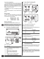
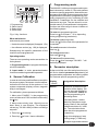
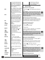
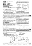
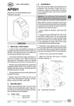
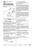
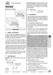
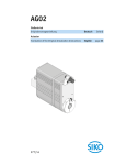
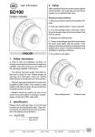
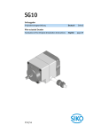
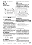
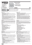
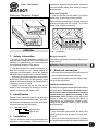
necessary, against environmental influences
such as sprayed water, dust, knocks, extreme
temperatures.
User Information
MA100/1
Built-in housing EG
Electronic Magnetic Display
• Push the device into the panel (1) until the
panel clips (2) hold the housing loosely.
EG
Press the lateral centering (3) slightly down and
push the housing into the cut-out (1) until the
panel clips (2) snap completely.
1
2
3
TG
ENGLISH
Fig. 1: Installation
1. Safety information
Bench housing TG
• In order to carry out installation correctly, we
strongly recommend this document is read very
carefully. This will ensure your own safety and
the operating reliability of the device.
• Your device has been quality controlled, tested and is ready for use. Please respect all
warnings and information which are marked
either directly on the device or in this document.
• Warranty can only be claimed for components
supplied by SIKO GmbH. If the system is used
together with other products, the warranty for the
complete system is invalid.
• Repairs should be carried out only at our
works. If any information is missing or unclear,
please contact the SIKO sales staff.
2. Identification
Please check particular type of unit and type
number from the identification plate. Type number and the corresponding execution are indicated in the delivery documentation.
The rubber feet can be removed in order to screw
down the unit.
Attention: Maximum screw length is 6.5 mm!
4. Electrical connection
• Wiring must only be carried out with power off!
• Provide standed wires with ferrules.
• Check all lines and connections before switching on the equipment.
Interference and distortion
All connections are protected against the effects
of interference. The location should be selected to ensure that no capacitive or inductive
interferences can affect the display or the
connection lines! Suitable wiring layout and
choice of cable can minimise the effects of
interference (eg. interference caused by switching power supplies, motors, cyclic controls
and contactors).
e.g. MA100/1-0023
Necessary steps:
type number
type of unit
3. Installation
• Only screened cable should be used. Wire
cross section is to be at least 0,14 mm2, max.
0,5 mm2.
The unit should be used only according to the
protection level provided. Protect the unit, if
• Wiring to screen and to ground (0V) must be
via a good earth point having a large surface area
MA100/1
Datum 15.05.2000
Art.Nr. 79918
Z.Nr. 8664079
Änd.Stand 160/00
7
for minimum impedance.
4.2 Conn., Bench Top Casing TG
• The unit should be positioned well away from
cables with interference; if necessary a protective screen or metal housing must be provided. The running of wiring parallel to the mains
supply should be avoided.
Reference switch
Interface
• Contactor coils must be linked with spark
suppression.
• PE-connection with 2.5 – 4 mm2 via PE-clamp
(fig. 2).
Sensor
Power supply
Power 230VAC, 110VAC
is made via mains connection on rear of the
device. The correct supply voltage is indicated
in the delivery documentation:
or
or
230 VAC -10% ... +6%
110 VAC -10% ... +6%
24 VDC -20% ... +20%
Sensor connection
via 9-poles rear side SUB-D socket (fig. 2).
Power 24VDC
Attention! No modifiction of the sensor connection, eg. by cable extension, is permitted.
Fig. 3: Rear panel connections TG
4.1 Connection, Panel Mounting EG
via a socket at the rear; pin connections are to
be made as follows (fig. 3):
Reference switch connection
No.
Description
1
2
3
RFS
+UB
GND
Interface connection
PE
1
2
3
4
5
6
7
8
9
8
Description
1
2
3
TXD / DÜA
RXD / DÜB
GND
Four membrane keys on the front panel are used
for programming and operation of the display.
Pin outs
RESET
UB = +24V (for reference switch)
GND (interface)
N.C.
RS232 (RXD), RS485 (DÜB)
RS232 (TXD), RS485 (DÜA)
PE
N (230/110 VAC), GND (24 VDC)
L (230/110 VAC), UB (24 VDC)
MA100/1
No.
5. Commissioning
Fig. 2: Pin outs EG
No.
via a socket at the rear; pin connections are to
be made as follows (fig. 3):
Datum 15.05.2000
Keys’ function
Depending on the operating mode the keys may
have additional functions (see 'Programming
mode' and 'Input mode'). The keys are pressed
singly or in pairs (two together).
Art.Nr. 79918
Z.Nr. 8664079
Änd.Stand 160/00
7. Programming mode
2
1
3
The MA100/1 is either pre-programmed to standard values at our works or, if the order defines
customer-specific parameters, these will be preprogrammed at SIKO. Enter programming mode
for parameter modification / programming. Normally programming is only necessary at initial
installation. Parameters can be modified and
checked at any time. They are stored in a nonvolatile memory. Each parameter’s designation,
function and value range is shown in tables on
the following pages.
4
1. Programming
2. Select 'value'
3. Select 'digit'
4. Store value
To enter into programming mode:
Press key for at least 1...30 s, depending
on key programming (see below).
Fig. 4: Key functions
When switched on
and correctly connected:
• the device name is displayed (for approx.1,5 s)
• the software version (eg. 1.00) is displayed
Subsequently the specific parameters of the
machine can be programmed.
Operating modes
There are two operating modes accessible via
the keyboard:
1. Programming mode: to program the display
at initial installation.
2. Input mode: to enter parameters/select
functions used during standard operation.
6. Sensor Calibration
In order to minimize possible offset errors within
the sensor system, the sensor must be calibrated before the first use of the system or if one
system component (display, sensor, magnetic
strip) is exchanged.
To leave programming mode:
Press key until the end of the parameter list
is reached.
To scroll parameter information:
Use key
To change parameters:
Use keys and
To store modified parameters:
Press key , then message "SAVING..." will
be briefly displayed.
8. Parameter description
At the end of this user information brochure you
will find a detailed parameter list showing all
programmable parameters and offering space
for customer-specific programming values .
Display
"choice"
Designation / description
RESOL:
Resolution: to determine the
resolution of the display. Display can be made in [mm] or
[inch]. Parameter "FREE" allows the programming of a
calculating factor.
FAC:
Calculating factor: used to
obtain for example an angle
display. Basis is the maximal
possible resolution of 1/1000
mm. The calculation factor
which has to be programmed
= measuring
For calibration, please proceed as follows:
1. Menu point "CALIBR.:" in the programming
menu must be set to "ON" and then confirmed by
the -key.
2. Move sensor slowly (max. 10mm/s) over at
least 10mm in one direction. The displayed
values (eg. "OC-001 +004") will then not change
anymore.
3. Press key
for storing.
4. Press key
to finish / leave calibration.
range to be displayed / total
working range [1/1000 mm].
Example: angle measurement
MA100/1
Datum 15.05.2000
Art.Nr. 79918
Z.Nr. 8664079
Änd.Stand 160/00
9
on a circular disk with a display range of 0 to180°; display in 1/100°; circumference
of the circular disk 942,48
mm; hence total working range 471,240 mm;
REF:
DEC.:
fore the first use of the system or if system components are exchanged.
9. Input mode
FAC = 18000 / 471240 = 0,03820
Reset function via keyboard
Absolute reference point for
the measuring system. This
value is determined by calibrating the system according
to chapter 9.
• Press key
value.
Decimal point: modification of
the decimal point position to
determine the resolution, eg.
after programming the calculation factor. Up to 5 digits
after the comma are possible.
DIR:
"UP"
"DOWN"
Direction: counting direction
of the measuring system
upward
downward
to set the display to the reference
Precondition: Parameter 'Reset enable' (RESET) in programming mode must be programmed to "ON", but unit must not be left in
programming mode (see chapter 7 'To leave
programming mode').
Reset function via reference input
By short activation (ground switching) of the
input RESET eg. by a push button or by using a
proximity switch. (Closing contact function)
Incremental measurement
Press key
for activation.
P KEY:
Time for which P-key needs
to be pressed to enter the
programming mode.
• The display is zeroed.
RESET:
Reset enable: reset to reference value via key .
Reset function on
Reset function off
to deactivate. The absolute
• Press key
measuring value is displayed again.
"ON"
"OFF"
ABS/REL:
"ON"
"OFF"
REF.EN.:
• Sign blinks.
incremental measurement enable.
function on
function off
"ON"
"OFF"
Ref. value input enable:
to enter / change calibration
value.
Reference value change on
Reference value change off
UNITS:
Unit of measure selection.
BRIGHT.:
LED display brightness toggle.
BAUD:
Baud rate: interface’s baud
rate.
LANGUAGE:
"GER"
"ENG"
Language: To choose the language displayed
German
English
CONTROL:
Nur für Servicezwecke
CALIBR.:
Fine calibration of the sensor.
Only has to be carried out be-
10
MA100/1
Datum 15.05.2000
Precondition: Menu point 'Incremental measurement enable' (ABS/REL) in programming mode
must be programmed to "ON", but unit must not
be left in programming mode (see chapter 7 ‚'To
leave programming mode').
Reference value modification
For reference value alteration, keys
be pressed simultaneously.
+
must
The display then shows the reference value,
which can be changed via the two arrow keys.
Press key
to store the new value.
MA100/1 returns to display mode, if
pressed.
key is
Precondition: In programming mode menu points
'Reference value input enable' (REF.EN.) respectively must be programmed to "ON", but
unit must not be left in programming mode (see
chapter 7 ‚'To leave programming mode').
Display during input mode
1
2
-
Art.Nr. 79918
3
4
5
6
7
8
9
1
7
.
9
1
3
Z.Nr. 8664079
10 11 12
m m
digit
display
Änd.Stand 160/00
No.Digit
Significance
1
sign (blinking during 'incremental
measurement')
mearuing value
unit of measure
2-9
11 - 12
12.
Application Examples
Length measurement
Display resolution 1/1000 mm.
Display shall be zeroed via function key.
Display
10. Trouble shooting
Error states are recognized and shown in the
display:
Message: OVERFLOW
Description: display overrun
Action: check parameters and adjust them if
necessary; set display to reference value
Message: SENSOR
Description: faulty / no sensor signal
Action: check gap between sensor and magnetic strip
Message / Effect: blinking SIGN / MA100/1
cannot be referenced
Description: Display is still in incremental
measurement function
Action: Leave incremental measurement
function as descriped in chapter 9 or proceed
as follows:
1. Enter into programming mode
2. Program parameter 'ABS/REL' to "ON"
3. Leave programming mode
4. Leave incremental measurement function
as descriped in chapter 8
5. Enter programming mode again
6. Program parameter 'ABS/REL' to "OFF"
7. Leave programming mode
Designation
Progr.value
RESOL:
resolution
0.001
REF:
reference value
000.000
DEC.:
decimal point
0.000
DIR:
counting direction
UP
P KEY:
time
1s
RESET:
reset enable
ON
ABS/REL: incr. meas. enable
OFF
REF.EN.:
reference value enable OFF
UNITS:
unit of measure
mm
BRIGHT.:
display brightness
38%
BAUD:
baud rate
19200
LANGUAGE:language
ENG
CONTROL:
OFF
CALIBR.:
fine calibration
OFF
11. List of commands / service
operation
Date:
30.05.1999
Software version: 1.01
Parameters:
1200...19200 Baud,
no parity, 8 bit,
1 stop bit, no handshake
Data code:
ASCII
Com- Length Reply
mand
Description
ax
2/8
l
1/2
w
1/4
abcd
z
1/9
+xxxxxxx(CR) position value(ASCII)
MA100/1
yyyyyyy(CR) yyy= Versionstext
x=0:unit
x=1:software version
> (CR)
Zero-setting
position value (two’s
complement) 4 byte
Datum 15.05.2000
Art.Nr. 79918
Z.Nr. 8664079
Änd.Stand 160/00
11
Appendix: Parameter list
Display
Designation / value range
RESOL:
resolution:
0.01, 0.001 (mm)
0.001i, 0.0001i (inch)
FREE
FAC:
calculating factor:
(only if resolution has been
programmed to 'FREE')
0.00001 ... 9.99999
REF:
reference value:
-999999 ... 999999
DEC.:
decimal point:
0. bis 0.00000
DIR:
counting direction: UP , DOWN
P KEY:
P Key-time:
1s, 5s, 10s, 20s, 30s
RESET:
reset enable: ON, OFF
ABS/REL:
incremental measurement enable:
ON, OFF
REF.EN.:
reference value input enable:
ON, OFF
UNITS:
mm, µm, m, cm, °, in, -- (no
units)
BRIGHT.:
display brightness:
4, 8, 15, 23, 38, 60, 100%
BAUD:
interface 's baudrate:
1200, 4800, 9600, 19200
Your programming I
Your programming II
LANGUAGE: GER, ENG
SIKO
GmbH
DR.-ING. G. WANDRES
Postanschrift / Postal address:
Postfach 1106
D-79195 Kirchzarten
Werk / Factory:
Weihermattenweg 2
D-79256 Buchenbach
Telefon / Phone 0 76 61 / 3 94 - 0
Telefax / Fax
0 76 61 / 3 94 - 388
Internet www.siko.de
12
MA100/1
Datum 15.05.2000
Art.Nr. 79918
Z.Nr. 8664079
Änd.Stand 160/00