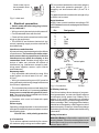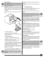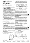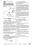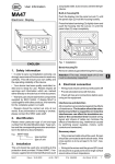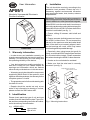
1
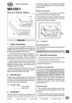
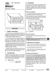
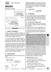
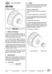
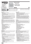
User Information
3. Installation
The unit should be used only according to the
protection level provided. Protect the unit, if
necessary, against environmental influences
such as sprayed water, dust, knocks, extreme
temperatures.
AP09/1
Absolute / Incremental Electronic
Position Indicator
Attention: The unit should not be exposed to
electromagnetic fields. Especially do not mount
close to adhesive or other permanent magnets.
Slide AP09/1 onto the solid shaft, insert torque
pin into the prebored mounting hole and use grub
screw M5 to fix the AP09/1's hollow shaft to the
machine's solid shaft (see fig. 1).
• Ensure sliding fit between solid shaft and
AP09/1.
• Ensure accurate shaft alignment and mount
the AP09/1 without force. Do not exceed the
values for the maximum axial and radial shaft
load. If the shaft is not correctly aligned, strain
on the bearings will result, which may cause
overheating and irreparable damage.
ENGLISH
1. Warrenty information
• In order to carry out installation correctly, we
strongly recommend this document is read very
carefully. This will ensure your own safety and
the operating reliability of the device.
• Your device has been quality controlled, tested and is ready for use. Please respect all
warnings and information which are marked
either directly on the device or in this document.
• Especially when using torque pin type A for
fixing, ensure that AP09/1 does not jam and that
it is mounted without strain. Please remember
this when choosing the AP09/1's bore diameter.
• Knocks on the unit should be avoided!
• Make sure that the axial seal is correctly
mounted ! (see fig. 2)
Torque pin type A : pin ø 6 h9
type B : bore ø 10 +0.8
• Warranty can only be claimed for components
supplied by SIKO GmbH. If the system is used
together with other products, the warranty for the
complete system is invalid.
• The guarantee period is 6 months starting with
the date of invoice.
• Repairs should be carried out only at our
works. If any information is missing or unclear,
please contact the SIKO sales staff.
2. Identification
Please check particular type of unit and type
number from the identification plate.Type number and the corresponding execution are indicated in the delivery documentation.
Fig. 1: Mounting instructions
e.g. AP09/1-0023
type number
type of unit
AP09/1
Datum 15.03.2001
Art.Nr. 80401
Z.Nr. 8665017
Änd.Stand 67/01
5
PE connection between the connector plugs is
to be linked with protective potential - fig. 3
(possibly use short strand with 2,5 mm2 to 4
mm2)!
Grub screw has to
be screwed in flush
to surface
For data transmission cables with a length of up
to 200m can be used.
Fig. 2: Axial seal
Serial interface
4. Electrical connection
• Switch power off before any plug is inserted or removed !!
• Wiring must only be carried out with power off.
• Provide standed wires with ferrules.
• Check all lines and connections before switching on the equipment.
• The AP09/1's and follower electronic's (eg.
control) operating supply must be switched on
simultaneously.
AP09/1 has a serial interface according to RS
485. Protocol: see enclosed page with software
description.
Pin
1
2
3
4
5
6
7
Designation
0V
+ UB
DÜA
DÜB
-
Interference and distortion
All connections are protected against the effects
of interference. The location should be selected to ensure that no capacitive or inductive
interferences can affect the display or the
connection lines! Suitable wiring layout and
choice of cable can minimise the effects of
interference (eg. interference caused by switching power supplies, motors, cyclic controls
and contactors).
contact plate
AP09/1
Necessary steps:
• Only screened cable should be used. Wire
cross section is to be at least 0,14 mm2, max.
0,5 mm2.
• Wiring to screen and to ground (0V) must be
via a good earth point having a large surface area
for minimum impedance.
• The unit should be positioned well away from
cables with interference; if necessary a protective screen or metal housing must be provided. The running of wiring parallel to the mains
supply should be avoided.
• Contactor coils must be linked with spark
suppression.
Power supply
Operating voltage depends on execution and is
indicated in the delivery documentation or on the
identification plate.
12 to 30 Vd.c., with polarity protection
4.1 Connection
Try to achieve optimal conductivity for connection between plug casings and contact plate.
6
AP09/1
Datum 15.03.2001
Fig. 3: Connection
PE-rail
4.2 Battery back-up
The lithium battery allows storage of programmed yparameters, current value and to capture
movements during power loss. Battery life is
approx. 5 to 8 years - depending on operating
time and frequency of moves during power loss.
When message "batt" is displayed then battery
should be exchanged by a SIKO agent or at the
parent company. In case you intend to exchange
the battery yourselves, please note the following
information.
Safety information
Attention-Battery: Inflammable, explosion and
burning hazard. Cannot be recharged and must
not be punctured, burned or exposed to temperatures above 100° C.
Art.Nr. 80401
Z.Nr. 8665017
Änd.Stand 67/01
Battery change
Only exchange battery when operating voltage is applied. Otherwise, when removing the
battery, the programmed parameters will be lost
after approx. 10 to 12 s.
The battery box is at the rear of the device under
the foam rubber seal. New, ready to be used
battery can be ordered from SIKO under article
code 80331.
To change the battery, please proceed as follows:
• Tighten fastening screws and glue foam rubber seal.
• Discharged batteries should be disposed of
safely.
5. Commissioning
Before the first use of the AP09/1, please check:
1. correct polarity of supply voltage.
2. correct cable connection and existence of
signals.
Note! Before starting bus operation each unit
must have been allocated its address. If one and
the same address is allocated several times,
bus operation will collapse.
Now the AP09/1 can be used.If necessary,
program the AP09/1's parameters according to
your requirements (see chapter ' Parameter
Description'). Check whether the AP09 functions
without problems (see chapter 'Operation/Key’s
function').
With built-in battery: Battery is tested automatically during operation. When battery voltage
falls below a certain value, "batt" is displayed
and a corresponding note is made under the
status bit in the AP09/1's protocol.
Operating modes
Two operating modes are possible.
Fig. 6: Battery change
• Remove AP09/1 from the spindle.
• Apply voltage supply (if it has been disconnected previously).
• Prepare new battery.
• Partially remove foam rubber seal (1).
• Battery box (3) can be removed after unscrewing the two fixing screws (2).
• Disconnect plug-and-socket connector.
• Insert new battery in reverse order. In case of
wrong polarization "batt" will be displayed. Turn
plug-and-socket connector by 180°.
• Strands must be carefully pushed into the unit
and must not be jammed or bent when the
battery box is inserted.
• To check correct battery installation, unit
must be disconnected from supply voltage.
Stand-alone operation:
Position is controlled from the display. Target
value and other parameters have already been
programmed before via interface.
Bus operation:
The interface allows to operate and control up to
31 AP09/1. Each AP09/1's parameters can then
be programmed /modified at any time and position value indicated.
Attention! In case of bus operation the last
AP09/1 on the bus system (the one located at the
end of the bus array) must be provided with a bus
terminating element. This plug-shaped accessory,
reference BAS09, can be purchased from SIKO.
Operation / Key's function / Parameter programming / Calibration etc., see enclosed page
with software description.
Attention: If AP09/1 then does not function,
programmed values will be lost within 10 to 12
seconds.
AP09/1
Datum 15.03.2001
Art.Nr. 80401
Z.Nr. 8665017
Änd.Stand 67/01
7
SIKO
GmbH
DR.-ING. G. WANDRES
Postanschrift / Postal address:
Postfach 1106
D-79195 Kirchzarten
Werk / Factory:
Weihermattenweg 2
D-79256 Buchenbach
Telefon / Phone 0 76 61 / 3 94 - 0
Telefax / Fax
0 76 61 / 3 94 - 388
Internet www.siko.de
8
AP09/1
Datum 15.03.2001
Art.Nr. 80401
Z.Nr. 8665017
Änd.Stand 67/01