1
ULTRADOSER SC350c
USER MANUAL
161 Baypointe Parkway
San Jose, CA 95134
+1 800.371.3303 Phone
+1 408.371.4932 Service
+1 408.577.1567 Fax
www.chartdosers.com
Table of Contents
Introduction ........................................................................................................................................ 3
Service .................................................................................................................................... 3
Manufacturer .......................................................................................................................... 3
Design Modification ............................................................................................................... 3
Additional Copies ................................................................................................................... 3
Safety .................................................................................................................................................. 5
Safety Bulletin ........................................................................................................................ 6
Receiving Your UltraDoser SC350c .................................................................................................. 8
Unpacking the UltraDoser SC350c ........................................................................................ 8
Overview and Utilities........................................................................................................................ 9
Product Specifications ............................................................................................................ 9
Utility Requirements .............................................................................................................. 9
UltraDoser Body Dimensions ........................................................................................................... 10
UltraDoser SC350c Components ..................................................................................................... 11
Installation ........................................................................................................................................ 13
Application Evaluation ......................................................................................................... 13
Support Stand Location ........................................................................................................ 13
Mounting the UltraDoser Unit.............................................................................................. 14
Installing the SC350c Controller .......................................................................................... 14
Connecting to the Distribution Block ................................................................................... 14
Installing the Nozzle ............................................................................................................. 15
Positioning the Dosing Head ................................................................................................ 15
Installing the Container Sensor ............................................................................................ 15
Principles of LN2 Dosing.................................................................................................................. 16
SC350c Controller Adjustments ....................................................................................................... 17
Controller Configuration Flow Chart ................................................................................... 17
System Information Screen .................................................................................................. 18
Alarm Screen ........................................................................................................................ 18
System Set Up ...................................................................................................................... 19
Speed Compensated Mode ............................................................................................................. 19
Fixed Delay Mode .......................................................................................................................... 25
SC350c Controller Set-up Verification ................................................................................ 27
Daily Operating Procedures (Dewar Fed System) ............................................................................ 28
Service and Maintenance .................................................................................................................. 30
General Trouble Shooting ................................................................................................................ 31
Replacement Parts ............................................................................................................................ 33
SC350c Controller Wiring Diagram ................................................................................................. 34
Warranty ........................................................................................................................................... 35
www.chartdosers.com
PN 1903
Page 2 of 35
Introduction
Thank you for your purchase of the Chart Inc. (Chart) UltraDoser SC350c Liquid Nitrogen (LN2)
Dosing System. Chart has designed and fabricated your system with attention to detail and
utilizing the leading cryogenic technologies to ensure a high efficient and reliable system.
Please contact us with any questions or comments that you may have. If after reading this manual
you are not confident in carrying out any task, please call Chart’s service team at +1 408.371.4932.
Service
Chart’s UltraDoser SC350c has been designed for years of safe and dependable operation. In the
event service is required, please contact Chart at:
Chart Inc.
161 Baypointe Parkway
San Jose, CA 95134 USA
www.chartdosers.com
+1 408.371.4932
Manufacturer
The UltraDoser SC350c is designed and manufactured by:
Chart Inc.
161 Baypointe Parkway
San Jose, CA 95134 USA
www.chartdosers.com
+1 800.371.3303
Design Modification
DO NOT use this product in a manner not consistent with the instruction outlined in this manual.
NEVER alter the design, or perform service that is not consistent with the instructions outlined in
this manual, without prior written approval of Chart.
Additional Copies
Additional copies of this manual are available by contacting Chart:
Chart Inc.
161 Baypointe Parkway
San Jose, CA 95134 USA
www.chartdosers.com
+1 800.371.3303
No part of this document may be reproduced in any form, or by any means, without the prior
written permission of Chart Inc.
Copyright 2011
Chart Inc.
www.chartdosers.com
PN 1903
Page 3 of 35
This manual is intended for use by Chart UltraDoser SC350c customers. It is important to read and
understand the information in this manual before installing or operating the system. This manual is
provided by Chart to its customers as a courtesy and, except as expressly provided in this manual,
CHART MAKES NO WARRANTIES, EXPRESS OR IMPLIED, REGARDING THE
CONTENTS IN THIS MANUAL. CHART ASSUMES NO REPONSIBILITY FOR ANY
OUTCOMES AS A RESULT OF USING THIS MANUAL.
SAFETY FIRST!
Liquid nitrogen must be handled properly. Without proper handling, severe frost bite, cryogenic
burning, oxygen deprivation, and bursting of sealed bottles (or containers) can result.
During this process, you may need:
Safety glasses with side shields and/or protective face shield
Insulated gloves for cryogenic service
Symbols and statements used throughout this text and their meaning are as follows:
Text following this symbol needs extra attention.
IMPORTANT: Text like this is extra information helpful to the situation
CAUTION: Text like this is information to help avoid personal injury and/or property damage.
WARNING!: Text like this is information to help avoid serious personal injury or death
and/or property damage.
www.chartdosers.com
PN 1903
Page 4 of 35
Safety
WARNING!: Your UltraDoser SC350c may be fed by a vacuum insulated pipe system
designed to contain pressurized, ultra-cold cryogenic liquids. These systems should only be
worked on by trained personnel to avoid serious injuries such as freezing, oxygen deficient
atmosphere and extremely high pressures.
WARNING!: Any configuration which allows a trapped volume of cryogenic liquid or
cold gas must be protected by a pressure relief valve. As the cold liquid/gas gains heat, the
contents will expand and increase in pressure. A section not protected by an over-pressure
relief valve will experience extremely high pressures and significant safety concerns.
WARNING!: Over pressurization of bottles (or containers) can occur while using
Chart’s UltraDoser SC350c potentially bursting the bottles (or containers). Proper
calibration of the UltraDoser SC350c ensures optimum nitrogen doses to avoid over
pressurization. Be sure to remove any bottles (or containers) that receive more than its
proper LN2 doses before sealing.
WARNING!: If you are at all unsure of how to safely work on this system, STOP and
contact Chart immediately at +1 408.371.4932.
CAUTION: As with any cryogenic system, it should be observed that any non-insulated piping
can get extremely cold and should not be touched by exposed skin. If the system requires
maintenance, it should be shutdown and allowed to warm up.
Strict compliance with proper safety and handling practices is necessary when using a
cryogenic system. We recommend that all our customers re-emphasize safety and safe handling
practices to all their employees and customers. While every possible safety feature has been
designed into the system and safe operations are anticipated, it is essential that the user of the
cryogenic system carefully read to fully understand all WARNINGS and CAUTION
IMPORTANTs listed in this safety summary and enumerated below. Also read the information
provided in the Safety Bulletin for Inert Gases following this Safety Summary. Periodic review of
the Safety Summary is recommended.
WARNING!: Nitrogen vapors in air may dilute the concentration of oxygen necessary to
support or sustain life.
Exposure to such an oxygen deficient atmosphere can lead to unconsciousness and serious injury,
including death.
CAUTION: Before removing parts or loosening fittings, empty the UltraDoser FS150 of liquid
and release any vapor pressure in a safe manner.
External valves and fittings can become extremely cold and may cause painful burns to personnel
unless properly protected. Personnel must wear protective gloves and eye protection whenever
removing parts or loosening fittings. Failure to do so may result in personal injury due to the
extreme cold and pressure in the system.
www.chartdosers.com
PN 1903
Page 5 of 35
WARNING!: Accidental contact of liquid gases with skin or eyes may cause a freezing
injury similar to a burn.
Handle liquid so that it will not splash or spill. Protect your eyes and cover skin where the
possibility of contact with liquid, cold pipes and equipment, or cold gas exists. Safety goggles or a
face shield should be worn if liquid ejection or splashing may occur or cold gas may exit forcefully
from equipment. Clean, insulated gloves that can be easily removed and long sleeves are
recommended for arm and hand protection. Cuff less trousers should be worn over the shoes to
shed spilled liquid.
Safety Bulletin
Portions of the following information are extracted from Safety Bulletin SB-2 from the
Compressed Gas Association, Inc. (CGA). For the full text of Safety Bulletin SB-2 and for more
information about oxygen atmospheres, refer to Safety Bulletin SB-2 from the Compressed Gas
Association, Inc. (CGA) at http://www.cganet.com. Additional information on nitrogen and liquid
cylinders is available in CGA Pamphlet P-9. Write to the Compressed Gas Association, Inc., 1235
Jefferson Davis Highway, Arlington, VA 22202 or visit their website at http://www.cganet.com.
Oxygen Deficient Atmospheres
The normal oxygen content of air is approximately 21%. Depletion of oxygen content in air, either
by combustion or by displacement with inert gas, is a potential hazard. Users should exercise
suitable precautions.
One aspect of this possible hazard is the response of humans when exposed to an atmosphere
containing only 8 to 12% oxygen. In this environment, unconsciousness can be immediate with
virtually no warning.
When the oxygen content of air is reduced to approximately 15 or 16%, the flame of ordinary
combustible materials, including those commonly used as fuel for heat or light, may be
extinguished. Somewhat below this concentration, an individual breathing the air is mentally
incapable of diagnosing the situation. The onset of symptoms such as sleepiness, fatigue, lassitude,
loss of coordination, errors in judgment and confusion can be masked by a state of "euphoria,"
leaving the victim with a false sense of security and well being.
Human exposure to atmosphere containing 12% or less oxygen leads to rapid unconsciousness.
Unconsciousness can occur so rapidly that the user is rendered helpless. This can occur if the
condition is reached by immediate change of environment, or through the gradual depletion of
oxygen.
Most individuals working in or around oxygen deficient atmospheres rely on the "buddy system"
for protection - obviously, the "buddy" is equally susceptible to asphyxiation if he or she enters the
area to assist an unconscious partner unless equipped with a portable air supply. Best protection is
obtainable by equipping all individuals with a portable supply of respiratory air. Lifelines are
acceptable only if the area is essentially free of obstructions and individuals can assist one another
without constraint.
www.chartdosers.com
PN 1903
Page 6 of 35
If oxygen deficient atmosphere is suspected or known to exist:
1. Use the "buddy system." Use more than one "buddy" if necessary to move a fellow
worker in an emergency.
2. Both the worker and "buddy" should be equipped with self-contained or airline breathing
equipment.
Nitrogen
Nitrogen (an inert gas) is a simple asphyxiant. It will not support or sustain life and can produce
immediate hazardous conditions through the displacement of oxygen. Under high pressure these
gases may produce unconsciousness even though an adequate oxygen supply, sufficient for life, is
detect.
Nitrogen vapors in air dilute the concentration of oxygen necessary to support or sustain life.
Inhalation of high concentrations of this gas can cause anoxia, resulting in dizziness, nausea,
vomiting, or unconsciousness and possibly death. Individuals should be prohibited from entering
areas where the oxygen content is below 19% unless equipped with a self-contained breathing
apparatus. Unconsciousness and death may occur with virtually no warning if the oxygen
concentration is below approximately 8%. Contact with cold nitrogen gas or liquid can cause
cryogenic (extreme low temperature) burns and freeze body tissue.
Persons suffering from lack of oxygen should be immediately moved to areas with normal
atmospheres. SELF CONTAINED BREATHING APPARATUS MAY BE REQUIRED TO
PREVENT ASPHYXIATION OF RESCUE WORKERS. Assisted respiration and supplemental
oxygen should be given if the victim is not breathing. If cryogenic liquid or cold boil-off gas
contacts a worker's skin or eyes, the affected tissues should be promptly flooded or soaked with
tepid water (105-115oF; 41-46oC). DO NOT USE HOT WATER. Cryogenic burns, which result in
blistering or deeper tissue freezing, should be examined promptly by a physician.
www.chartdosers.com
PN 1903
Page 7 of 35
Receiving Your UltraDoser SC350c
The UltraDoser SC350c is designed for filling line speeds up to 350 bottles (or containers) per
minute. It can compensate for changes in line speed up to 350 bottles (or containers) per minute.
Line speeds greater than 350 bottles (or containers) per minute will prompt the UltraDoser SC350c
to continuously dose (in lieu of discrete / pulse dosing) until the line speed returns to less than 350
bottles (or containers) per minute.
Unpacking the UltraDoser SC350c
The UltraDoser SC350c will arrive in a specially designed shipping crate. If the unit is intended to
be moved from one location to another, storing the crate for future use is ideal.
Upon arrival of the UltraDoser SC350c, it is advised to immediately inspect for any signs of
damage. If any damage occurred in shipping, claims must be filed with the shipping carrier
immediately prior to unpacking the UltraDoser SC350c.
While unpacking the crate, all contents should be carefully inspected. Things to check for upon
arrival include:
Dents in the UltraDoser unit
Male and female bayonets should be protected.
Proper number of bayonet clamps/flanges and o-rings (one set for every female bayonet).
Any other components that were defined to ship loose
If there are any pieces listed on the Pack Slip and/or Materials List not in the shipping crate please
contact Chart immediately at +1 800.371.3303.
CAUTION: When removing the UltraDoser unit from the crate, gently set it on the ground. Do
not drop the UltraDoser unit! When transporting the UltraDoser unit through the facility, be sure
to carry with care. Take care not to run into walls or drag the UltraDoser unit on the ground.
Prior to installation, the UltraDoser SC350c should be stored in a location that will prevent dirt,
water or other debris from getting inside the system. Similarly, it should be stored in a place that is
generally out of the way of frequent traffic to reduce the risk of damage. Chart recommends
storing the system in the crate when not in service.
www.chartdosers.com
PN 1903
Page 8 of 35
Overview and Utilities
Product Specifications
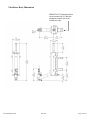
UltraDoser Body Dimensions:
Reservoir height: 18” (457mm)
Hexagonal: 6” (197mm)
Arm reach : 12” or 18” (305mm or 457mm) from stand dependent on
mounting bracket location
UltraDoser Dosing Head:
2”W x 9.5”H (51mm x 241mm)
Total Weight (w/electronics):
UltraDoser: 32 lbs (14.5kg)
SC350c Controller: 10.5 lbs (4.8kg)
Dosing Range:
0.01 – 14 grams/dose
Dosing Accuracy:
+/- 5% of dose value
Timing Range:
15 ms – 1000 ms (in 1 ms intervals)
Control Voltage:
24 VDC
Materials:
Stainless steel construction
Built to food and beverage industry standards
Crate Dimensions:
59”L x 29”W x 21”H (1499mm x 737mm x 533mm)
225 lbs (102kg) with support stand
140 lbs (64kg) without support stand
Utility Requirements
Electrical Supply:
100-240 VAC 50-60Hz 110 W
Liquid Nitrogen:
Portable Dura-Cyl dewar – 22 psi (1.5 bar)
House System (with Chart Phase Separator) – 100 psi (6.9
bar)
Maximum flow rate 15 gallons (56 liters) per hour
Gaseous Nitrogen:
60 to 100 psi (4.1 to 6.9 bar)
10 SCFH gas per 100 bottles (or containers) per minute
www.chartdosers.com
PN 1903
Page 9 of 35
UltraDoser Body Dimensions
IMPORTANT: Mounting bracket
can be mounted at 90° intervals
around the central axis of the
UltraDoser body.
www.chartdosers.com
PN 1903
Page 10 of 35
UltraDoser SC350c Components
UltraDoser Body
The stainless steel vacuum insulated reservoir provides a working supply of LN2 for dosing
operations from your liquid nitrogen supply.
Distribution Block
This electrical connection “block” houses the connections between the operating parts of the
UltraDoser unit and the SC350c controller.
Bayonet Connection
The bayonet connection allows a completely vacuum insulated, warm, and frost-free connection
between the CryotechFlex hose and the UltraDoser unit.
CryotechFlex Hose
A vacuum insulated hose that provides a connection between the UltraDoser unit and the LN2
supply.
Inlet Filter
A 10 micron stainless steel inlet filter is provided. The filter needs to be installed inside the male
bayonet on the CryotechFlex hose.
ElectroPneumatic (EP) Actuated Valve (if ordered)
If ordered, the UltraDoser has an ElectroPneumatic actuated dosing valve. The valve is driven by a
pneumatic cylinder. Gas pressure to the cylinder is controlled by a 24 volt solenoid valve.
Dosing Head
The dosing head delivers the dose of LN2.
Dosing Valve Assembly
The dosing valve assembly contains the solenoid coil, the electromagnetic core with the valve
stem, the return spring and the sealed valve housing.
Valve Confirm Assembly
The valve confirm assembly is attached to the pneumatic cylinder. The sensor confirms that the
valve stem was lifted and dosing occurred.
Dosing Head Heater
The UltraDoser unit has a self-regulating dosing head heater. The maximum temperature of the
dosing head heater is 150ºF (65ºC) and prevents frost or ice formation at the dosing head area. The
heater is held in place by a set of o-rings. If needed, the dosing head heater can be removed by
slipping it off of the dosing head.
The dosing head heater has a built-in splash guard to minimize the dosing nozzle’s exposure to
splashed product or LN2.
www.chartdosers.com
PN 1903
Page 11 of 35
Dosing Nozzle
The size of the dosing nozzle directly affects the amount of LN2 dosed. 0.040” ID, 0.050” ID, and
a 0.060” ID nozzles ship loose with the LN2 Dosing System. Custom sizes may be ordered from
Chart.
SRV / Drain Plug
A 50psi SRV / drain plug are located on the back of the UltraDoser unit. When removed, this
allows the LN2 to drain from the UltraDoser body.
The 50psi safety relief valve (SRV) is provided to protect the unit against over pressurization. If
the pressure inside the unit reaches 50 psi or greater, the safety relief valve will vent excess
pressure. Under normal operating conditions, the SRV should not vent.
Mounting Bracket Assembly
The UltraDoser unit is supplied with a mounting bracket assembly. The assembly consists of the
bracket attaching to the UltraDoser unit and two clamps. These clamps are designed to fit on
Chart’s support stand or 1-1/2” stainless steel rod. The bracket can be mounted in 3 positions. See
page 16 for additional information.
Vent Heater
The UltraDoser unit has a self-regulating vent heater. The maximum temperature of the vent
heater is 150ºF (65ºC) and prevents frost or ice formation at the vent area. The heater is held in
place by a set of o-rings. If needed, the vent heater can be removed by slipping it off of the vent
area.
SC350c Controller
SC350c controller dictates the dosing operation of the system.
Dosing Head Pressure Gauge
The dosing head pressure gauge measures the head pressure of the liquid nitrogen in the reservoir
and acts as a liquid level indicator. The pressure gauge should read between 0.4 – 0.5 psi when the
reservoir is full.
Gas Regulator Pressure Gauge
The regulator controls the pressure of the gaseous nitrogen to the actuator. The regulator is preset
to 60 psi. If necessary, on-site adjustments may be made. Only gaseous nitrogen should be used in
this application. Air, even if it is dry compressed air, should NEVER be used as an alternative.
Source Pressure Gauge
This gauge measures the pressure of the liquid nitrogen source. This pressure reading should read
between 3-22psi depending on the source of liquid nitrogen (house system or Dura-Cyl dewar fed).
www.chartdosers.com
PN 1903
Page 12 of 35
Installation
Application Evaluation
The UltraDoser can be used for both inerting and pressurization applications. The application must
be evaluated to determine the ideal location of the dosing head on the filling line.
Inerting – Inerting is the process of removing oxygen (O2) from a container or package.
To inert a container, a relatively large dose of LN2 is introduced into the container. The
liquid dose then converts into gas displacing air and oxygen from the container. A plastic
cover may be placed over the dosed containers so that O2 is not allowed to re-enter the
container before capping. The ideal location must allow for enough time between dosing
and capping so that the liquid dose is converted into a gas.
Pressurization – Pressurization occurs when LN2 is introduced into container or package.
The container is then capped or sealed to capture the expanding gas. To pressurize a
container, a relatively small dose of LN2 is introduced into the container immediately
before the container is capped or sealed.
Support Stand Location
The UltraDoser unit is supplied with a mounting bracket assembly. The assembly consists
of the bracket attaching to the UltraDoser body and two clamps designed to fit on
1½”stainless steel rod. Chart can supply a prefabricated stand to accommodate the
mounting bracket assembly. This stand can be utilized in almost all installations. If the
Chart stand cannot be used in your installation, fabricating one with 1½”diameter rod or
round bar will make installation of the UltraDoser SC350c simpler. The following
instructions will assume installation of Chart’s prefabricated support stand (Figure 4).
Figure 1
Figure 2
Figure 3
Figure 4
1. The UltraDoser unit can be installed on either side of a production line. Select the side that
best suits the workplace. The mounting bracket assembly is installed straight back opposite
to the arm from the factory. However, the UltraDoser body can be mounted in the
mounting bracket such that the support stand is located on either side perpendicular to the
arm (Figure 1-3).
2. Measure the appropriate distance depending on the UltraDoser configuration. This is the
location for the installation of the support stand.
3. Mark the location of the stand and install the four (4) 5/8” bolts included with the support
stand in the proper locations.
www.chartdosers.com
PN 1903
Page 13 of 35
Mounting the UltraDoser Unit
Once the stand is installed, mount the UltraDoser unit on the stand using the supplied mounting
bracket.
Installing the SC350c Controller
Mount the SC350c controller at a convenient location. Brackets are supplied to mount the
controller on the Chart prefabricated support stand or 1½”diameter rod or round bar.
There are three connections on the bottom of the SC350c controller.
Input Power (J-1)
The SC350c controller power cable is connected to the SC350c controller at port J-1.
Interface Connection (J-2)
The interface cable, a component of the distribution block, is connected to the SC350c
controller at port J2.
Speed Sensor (J-3)
The SC350c controller requires a speed sensor when operating in “Speed Compensated”
mode. The PNP speed sensor should be connected to the SC350c controller at port J-3.
Connecting to the Distribution Block
The electrical connection “block” houses the connections between the operating parts of the
UltraDoser unit to the SC350c controller.
Vent Heater (D-1)
This is the connector marked D-1 on the distribution block. A green light on the cable
connector indicates that power is being supplied to the vent heater.
Nozzle Heater (D-2)
This is the connector marked D-2 on the distribution block. A green light on the cable
connector indicates that power is being supplied to the nozzle/dosing head heater.
Timing/Container Sensor (D-3)
This is the connector marked D-3 on the distribution block. A green light on the cable
connector indicates that power is being supplied to the sensor. A yellow light will appear
whenever a container is detected.
Dose Solenoid (D-4)
This is the connector marked D-4 on the distribution block. A green light on the cable
connector indicates that power is being supplied to the solenoid valve. A yellow light will
appear whenever the solenoid valve has been activated.
Confirm Sensor (D-5)
This is the connector marked D-5 on the distribution block. A green light on the cable
connector indicates that power is being supplied to the solenoid valve. A yellow light will
appear whenever the pneumatic cylinder has lifted the valve stem.
www.chartdosers.com
PN 1903
Page 14 of 35
Installing the Nozzle
Three nozzles are supplied with the UltraDoser SC350c – 0.040”, 0.050”, and 0.060”. Custom
sizes may be ordered from Chart.
1.
2.
3.
4.
5.
Remove the dosing head heater.
Select a nozzle.
Insert the nozzle into the nozzle tool, threads out.
Thread the nozzle into the dosing head area in a clockwise direction. Do not over torque.
Re-apply the dosing head heater.
CAUTION: Never use an ice-pick, screwdriver, torch, or similar devices on the dosing head. The
ribs of the internal bellows are a thin walled metal and the hole on the outer ring of the dosing head
is a positive pressure port to help keep moisture out and ice from forming. High heat and puncture
holes will destroy the vacuum insulation and VOID WARRANTY.
Positioning the Dosing Head
The dosing head should be directly over the bottle (or container) opening. The dosing head is
typically installed 1/2” - 3/4” above the bottle (or container) opening. The UltraDoser unit must be
manually adjusted to accommodate different sized bottles (or containers) running on the same
production line.
Installing the Container Sensor
The container sensor must be a PNP type sensor and must be installed for the UltraDoser SC350c
to operate correctly. The optimal distance from the dosing head center to bottle (or container)
detection is approximately 3/4 the distance between containers.
For example: If the centerline distance between two bottles (or containers) is 4.75 inches (120
mm), then mount the container sensor approximately 3.50 inches (89 mm) from the center of the
dosing head.
Installing the Speed Sensor
The speed sensor must be a PNP type sensor and must be installed for the UltraDoser SC350c to
operate in “Speed Compensated” mode and must provide a continuous stream of pulses. Visually
or electronically check that the speed sensor is generating a steady stream of pulses. The speed
sensor should be installed with twisted and shielded wire to prevent noise from corrupting the
speed pulses.
www.chartdosers.com
PN 1903
Page 15 of 35
Principles of LN2 Dosing
To ensure consistent dosing results, an accurate dose must be delivered to each bottle (or container)
AND each bottle (or container) must be processed in the same manner.
Chart’s UltraDoser SC350c guarantees that a precise, accurate dose of LN2 is delivered. The
UltraDoser SC350c meets the following fundamental dosing conditions.
Pure Liquid at the Dosing Head
Pure liquid (i.e. liquid with no gas pockets) must be instantaneously available at the dosing head.
Chart has a unique internal design that ensures the continual availability of pure liquid at the
dosing head.
Constant Pressure
Constant pressure at the dosing head is a critical requirement for reproducible dose size. The unit
utilizes a float valve that allows for a stable liquid level. This allows the pressure at the dosing
head to remain constant during operation.
Dose Duration
The dose duration is tightly controlled by the SC350c controller’s electronics. Dose duration is
measured in milliseconds.
IMPORTANT: The following production conditions must be controlled to ensure consistent
dosing results:
1. Product bottle (or container) fill levels must be consistent.
2. Product bottle (or container) fill temperatures must be consistent.
3. Capping techniques must be consistent.
4. Product may not be spilled or splashed out of bottles (or containers) following dose.
IMPORTANT: Enough time must be allowed for specific dosing operations. When using the
UltraDoser SC350c for inerting purposes (removal of oxygen) time must be allowed between
dosing and complete capping of the bottle (or container). See “Inerting”, page 13, for additional
information.
www.chartdosers.com
PN 1903
Page 16 of 35
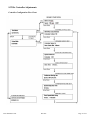
SC350c Controller Adjustments
Controller Configuration Flow Chart
www.chartdosers.com
PN 1903
Page 17 of 35
System Information Screen
This System Info sub menu is where the software version is shown. This would only be accessed
for upgrade or troubleshooting purposes. This screen is used to view the software version number.
It would only be viewed if the controller was being repaired or upgraded. The operator cannot
change this screen. This screen does not affect system operation.
Alarm Screen
The software alerts the user for the following reasons:
1. If it detects speed sensor failure after a container has been detected;
2. The dosing valve has not been activated after a container has been detected; or
3. The controller DOSE ENABLE switch is in the disable mode, “0”.
The alert will appear as a flashing triangle in the Display Screen. The flashing triangle will
disappear once the alarm condition has been resolved.
www.chartdosers.com
PN 1903
Page 18 of 35
System Set Up
The software is programmed for the dosing head to be installed 3/4” or less above the container.
The container sensor and the speed sensor must be installed for the unit to operate correctly.
Verify installation and functionality of both sensors prior to continuing with the setup procedure.
Pull out the emergency off switch and verify the unit powers up. The EMO switch is located on the
front of the controller. When pushed, the electric supply for the entire controller will be shut
down.
Speed Compensated Mode
IMPORTANT: In Speed Compensated Mode, the UltraDoser unit relies on the PNP speed sensor
to dispense liquid nitrogen. Parameters must be entered into the SC350c controller based on the
sensor and bottle (or container) distances. Failure to enter the correct parameters may result in
missed doses.
1. On the controller, turn the DOSE ENABLE switch to the disable mode, “0”.
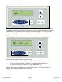
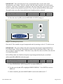
2. From DISPLAY (Image 1) press ESC to go to SETUP (Image 2).
Image 1: Display Screen
IMPORTANT: Under normal operation, this screen will be displayed.
The system defaults to DISPLAY at power up. This screen shows the dose duration, the current
speed of the line in containers per minute (cpm), and the current dosing mode: “SCMP” for Speed
Compensated Mode or “FXDD” for Fixed Delay Mode.
www.chartdosers.com
PN 1903
Page 19 of 35
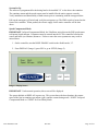
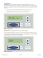
Image 2: Setup Screen
3. Use the arrow key ▲ or ▼ to highlight “Setup Mode”. Press ENTER.
IMPORTANT: After 1 minute, the panel will return to DISPLAY.
4. Use the arrow key ▲ or ▼ to highlight OPERATOR INPUT. Press ENTER to activate
CONTAINER DISTANCE SETUP (Image 3).
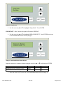
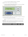
Image 3: Container Distance Setup Screen
Input the container to container distance using the arrow key ▲ or ▼ and then press ENTER.
Input Limits
Distance Between Container Centers
Distance Between Container Centers
Units
Maximum
Inches
20
Millimeters 500
Minimum
2
50
5. Press the arrow key ▼ to activate CONTAINER SENSOR SETUP (Image 4).
www.chartdosers.com
PN 1903
Page 20 of 35
Image 4: Container Sensor Setup Screen
Input the Container Sensor to Dose center distance using the arrow key ▲ or ▼ and then press
ENTER.
Function
Container Sensor to Dose Center Distance
Container Sensor to Dose Center Distance
Units
Inches
Millimeters
Maximum
20
500
Minimum
0
0
6. Press the arrow key ▼ to activate PULSES PER CONTAINER SETUP (Image 5).
Image 5: Pulses Per Container Setup Screen
Input the Speed Pulses per Container using the arrow key ▲ or ▼ and then press ENTER.
IMPORTANT: The number of pulses does not have to be a whole number. This is a critical
parameter of the system and care should be taken to input the correct value.
www.chartdosers.com
PN 1903
Page 21 of 35
Determining Speed Pulses per Container
Speed pulses per container can be determined by observing the light pulses on both the container
and speed sensors. If there are three speed light pulses per container pulse, the speed pulses per
container would be 3. The unit will accept a decimal number (3.4) of speed pulses per container if
the setup does not have an even number of speed pulses per container.
In cases where the lights on the container and speed sensors are not visible, the controller can be
opened and light pulses on inputs IO.1 (Speed Sensor) and IO.2 (Container Sensor) can be counted.
Only trained personnel should attempt this method as improper handling could void the warranty,
or damage the product.
Function
Speed Pulses Per Container
Units
Count
Maximum
12.00
Minimum
1.00
7. Press the arrow key ▼to activate DOSE DURATION SETUP (Image 6).
Image 6: Dose Duration Setup Screen
Input the Dose Duration using the arrow key ▲ or ▼ and then press ENTER.
Function
Dose Time
Units
Milliseconds
Maximum
1000
Minimum
15
8. Press the arrow key ▼to activate CONTINUOUS DOSING SPEED SETUP (Image 7).
www.chartdosers.com
PN 1903
Page 22 of 35
Image 7: Continuous Dosing Speed Setup Screen
Input the Continuous Dosing Line Speed using the arrow key ▲ or ▼ and then press ENTER.
Function
Continuous Dosing Line Speed
Units
Containers per Minute
Maximum
350
Minimum
100
IMPORTANT: When the line speed exceeds the “Continuous Dosing Line Speed” (factory set at
350 containers per minute), a continuous stream of liquid nitrogen will be dispensed if containers
are present. Nitrogen that misses the bottle and hits either the floor or other machinery may form
ice form in the area.
9. Press the arrow key ▼to activate SYSTEM RESPONSE TIME SETUP (Image 8).
Image 8: System Response Time Setup Screen
Input the System Response Time the arrow key ▲ or ▼ and then press ENTER.
www.chartdosers.com
PN 1903
Page 23 of 35
IMPORTANT: The System Response Time is an adjustment that is used to make small
adjustments to valve timing. It may be required when the normal setup does not correctly dose
containers. This feature is intended to compensate when the dosing head is greater than 3/4 inch
from the container or the pneumatic pressure (GN2) is near the operational limits of the system.
The initial value is set at the factory and does not normally need to be adjusted.
Function
System Response Time
Units
Milliseconds
Maximum
60
Minimum
20
10. Press the arrow key ▼to activate FIXED DELAY SETUP (Image 9).
Image 9: Fixed Delay Setup Screen
Place the SC350c controller in speed compensated mode by entering a value of “0” in this screen.
IMPORTANT: This screen changes the mode of operation from Speed Compensated Mode to
Fixed Delay Mode. When this screen indicates that the Fixed Speed Mode Delay is 0msec, the
unit is in Speed Compensated Mode. When there is any other time value set in this screen, the unit
is in Fixed Delay Mode.
In Fixed Delay Mode, the UltraDoser dispenses liquid nitrogen defined by the user defined
milliseconds REGARDLESS of the line speed.
Function
Fixed Speed Mode Delay
Units
Milliseconds
Maximum
5000
Minimum
0
11. From FIXED DELAY SETUP, press ESC to return to DISPLAY.
12. Use the arrow key ▲ or ▼ to highlight SCREEN DISPLAY. Press ENTER to activate
DISPLAY.
13. On the controller, place the DOSE ENABLE switch in the enable mode “1”.
www.chartdosers.com
PN 1903
Page 24 of 35
Fixed Delay Mode
IMPORTANT: Fixed Delay Mode is designed for steady speed filling lines. It does not
compensate for changes in line speed. Therefore, you should initialize the system at the intended
line speed. Any changes to the line speed may require changes to the dose settings: fixed delay and
dose time.
1. On the controller, turn the DOSE ENABLE switch to the disable mode, “0”.
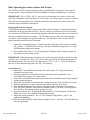
2. From DISPLAY (Image 10) press ESC to go to SETUP (Image 11).
Image 10: Display Screen
IMPORTANT: Under normal operation, this screen will be displayed.
The system defaults to DISPLAY at power up. This screen shows the dose duration, the current
speed of the line in containers per minute (cpm), and the current dosing mode: “SCMP” for Speed
Compensated Mode or “FXDD” for Fixed Delay Mode.
Image 11: Setup Screen
www.chartdosers.com
PN 1903
Page 25 of 35
1. Use the arrow key ▲ or ▼ to highlight “Setup Mode”. Press ENTER.
IMPORTANT: After 1 minute, the panel will return to DISPLAY.
2. Use the arrow key ▲ or ▼ to highlight OPERATOR INPUT. Press the arrow key ▼until
FIXED SPEED MODE DELAY is visible (Image 12).
Image 12: Fixed Speed Mode Delay Screen
Place the unit in “Fixed Delay” mode by entering a value other than “0” in this screen. The entered
value will be the delay the system uses to dose containers.
3. Use the arrow key ▲ or ▼to select the desired delay. Press ENTER to set the displayed
value.
IMPORTANT: A delay of 40 will delay the dose for 40 milliseconds. This value is the delay
between the time a bottle (or container) is detected and the dosing valve is opened. The closer the
container sensor is to the dosing head, the shorter the time delay.
Function
Fixed Speed Mode Delay
www.chartdosers.com
Units
Milliseconds
PN 1903
Maximum
5000
Minimum
0
Page 26 of 35
4. Use the arrow key ▲ or ▼until DOSE DURATION appears (Image 13).
Image 13: Dose Time Screen
The dose time setting controls the amount of time (in milliseconds) that the dosing valve is open.
The amount of LN2 that is trapped inside a container depends on many variables including the
position of the dosing head, the position of the capper, the size of the dosing nozzle, the
temperature of the container contents, fill levels and head space. Therefore, the time setting for
each filling operation must be evaluated.
Function
Dose Time
Units
Milliseconds
Maximum
1000
Minimum
15
5. On the controller, place the DOSE ENABLE switch in the enable mode, “1”.
SC350c Controller Set-up Verification
Send a bottle (or container) down the filling line. Note if the dose is dispensed before, in, or after
the bottle (or container). If the dose is dispensed BEFORE the bottle (or container) reaches the
dosing head, INCREASE the dose delay until the dose is dispensed into the bottle (or container). If
the dose is dispensed AFTER the bottle (or container) reaches the dosing head, REDUCE the dose
delay.
IMPORTANT: To verify that the dose is being dispensed into the container, fill the container with
water and look for the tell-tale “fog” from the dose of LN2 on the water.
IMPORTANT: If the container sensor is far from the dosing head and the time delay is
large, be sure to do a trial run at line speed. The electro-pneumatic solenoid valve does not record
signals from the sensor while it is dosing or in a delay mode from the previous signal. During the
initial set up, one should verify that all containers are receiving a dose.
www.chartdosers.com
PN 1903
Page 27 of 35
Daily Operating Procedures (Dewar Fed System)
The UltraDoser SC350c unit can be fed by either a portable Dura-Cyl dewar or a house liquid
nitrogen system. Most UltraDoser SC350c installations will utilize portable Dura-Cyl dewars.
IMPORTANT: LN2 is -320ºF (-196ºC). Any water and/or moisture can cause ice which will
affect the performance of the UltraDoser SC350c system. Providing a positive pressure of ambient
GN2 (also known as purging) to the UltraDoser unit before introducing LN2 into the body will
eliminate many performance interruptions.
Purging with Gaseous Nitrogen
The UltraDoser unit must only be purged with ambient gaseous nitrogen. Chart recommends the
UltraDoser unit be purged when not in use. However, this may not be practical for all operators.
At a minimum, the UltraDoser unit should be purged to eliminate any water that may be inside the
unit after installation and prior to startup,. The UltraDoser reservoir may also require purging
when there is liquid nitrogen flowing out of the vent. The UltraDoser reservoir must also be
purged when the nozzle becomes frozen shut.
1. Attach the CryotechFlex hose (½” female flare side) to the house GN2 system or portable
GN2 cylinder. **IMPORTANT: this step will require additional fittings such as ½” male
flare fitting and compression fittings.
2. Flow ambient GN2 (20 psi; 1.38 bar) through the UltraDoser body for approximately ten
(10) minutes before system start up.
IMPORTANT: When purging the UltraDoser unit, it will vent heavily and there will be a steady
stream of “fog” from the vent. This “fog” will be cold to the touch if the internal temperature of
the UltraDoser unit is still at or near LN2 temperatures (-320 ºF; -196 ºC). Once the UltraDoser
unit is at or near ambient temperature, the “fog” will warm up.
System Start Up
1. Remove the CryotechFlex hose from the GN2 outlet with a 7/8” open end wrench or
adjustable crescent wrench.
2. Insert the supplied 10 micron filter into the male bayonet on the supplied 10 foot
CryotechFlex hose using a 1/8” allen wrench.
3. Attach the CryotechFlex hose (male bayonet side) to the UltraDoser unit with the supplied
bayonet clamp and gasket.
4. Attach the CryotechFlex hose (female flare fitting side) to the 22psi LN2 Dura-Cyl dewar.
5. Open the liquid valve (counter-clockwise direction) on the Dura-Cyl dewar.
6. Wait until the UltraDoser unit is filled with liquid nitrogen, approximately 10 minutes.
7. Place the DOSE ENABLE switch on the controller to the “0” position. This will prevent
the UltraDoser from dosing until the operator is ready.
8. Turn the controller “ON” by pulling the EMO button out. The front panel will show the
DISPLAY screen if the controller is functioning correctly.
9. Adjust the dosing parameters. See “SC350c Controller Adjustments”, page 21, for
additional information.
10. Place the DOSE ENABLE switch on the controller to the “1” position. This will allow the
unit to begin dosing.
www.chartdosers.com
PN 1903
Page 28 of 35
IMPORTANT: When the UltraDoser unit is filling, it will vent heavily and there will be a steady
stream of “fog” from the vent. Once the UltraDoser unit is filled, there will be a “wisp” of fog
coming from the vent. If the UltraDoser unit overfills and liquid nitrogen starts dripping out the
vent, close the liquid valve on the Dura-Cyl dewar and call Chart service at +1 408.371.4932.
System Shut Down
1. Place the DOSE ENABLE switch on the controller to the “0” position. This will stop the
machine from dosing nitrogen.
2. Shut the liquid valve (clockwise direction) on the Dura-Cyl dewar.
3. If possible, purge with GN2 until next use. See “Purging with Gaseous Nitrogen”, page 25,
for additional information.
IMPORTANT: Rotate the Dose Enable switch to the “0” position if the system will not be used
for a period of time; example an 8hr. shift. This will disable the dosing function but allow the
system to continue to supply power to the dosing and vent heaters to prevent ice build-up.
Dura-Cyl Dewar (22psi) Change Out Procedure
The Dura-Cyl dewar will need to be changed out from time to time. The operator should visually
check the gauges on the Dura-Cyl dewar to monitor the internal liquid level. When the gauges read
low levels, it must be swapped with a full Dura-Dyl dewar.
1. Shut the liquid valve (counter-clockwise direction) on the Dura-Cyl dewar.
2. Disconnect the CryotechFlex hose from the Dura-Cul dewar using a 7/8” open end wrench
or adjustable crescent wrench.
3. Connect the CryotechFlex hose to the liquid outlet on the full Dura-Cyl dewar using a 7/8”
open end wrench or adjustable crescent wrench.
IMPORTANT: The UltraDoser SC350c will continue to dose properly until the liquid level
inside the UltraDoser unit runs low. This feature gives the operator a reasonable window in which
to change out the Dura-Cyl dewar without disrupting the production operation.
www.chartdosers.com
PN 1903
Page 29 of 35
Service and Maintenance
Nozzle Change Procedure
1. Remove the dosing head heater.
2. Insert the nozzle tool into the nozzle area until the tool connects with the nozzle.
3. Remove the nozzle with the driver in a counter-clockwise direction. Remove.
4. Once the nozzle is removed, place the new nozzle or cleaned nozzle into the nozzle tool
and insert in a clockwise direction.
CAUTION: The dosing head heater may still be in operation. Do not expose skin to prolonged
contact with the dosing head heater. The maximum temperature of the dosing head heater is 150ºF
(65ºC).
IMPORTANT: Always perform nozzle change out procedures before introducing LN2 into the
UltraDoser unit. Failure to do so may cause the nozzle to unthread and fall out.
IMPORTANT: If the nozzle does not loosen easily, drain the UltraDoser unit through the SRV /
drain plug and warm up nozzle with a low voltage heat gun.
Nozzle Cleaning Procedure
1. Remove the nozzle from the UltraDoser. See “Nozzle Change Out Procedure” above.
2. Clean the nozzle opening with a very thin wire and blow dry nitrogen through it.
3. Thoroughly dry the nozzle with dry nitrogen gas before re-installing.
IMPORTANT: Any moisture left on the nozzle will immediately freeze up when the nozzle is reinstalled which may cause the nozzle to unthread and fall out.
Purging with Gaseous Nitrogen
The UltraDoser unit must only be purged with ambient gaseous nitrogen. Chart recommends the
UltraDoser unit be purged when not in use. However, this may not be practical for all operators.
At a minimum, the UltraDoser unit should be purged to eliminate any water that may be inside the
unit after installation and prior to startup,. The UltraDoser reservoir may also require purging
when there is liquid nitrogen flowing out of the vent. The UltraDoser reservoir must also be
purged when the nozzle becomes frozen shut.
1. Attach the CryotechFlex hose (½” female flare side) to the house GN2 system or portable
GN2 cylinder. **IMPORTANT: this step will require additional fittings such as ½” male
flare fitting and compression fittings.
2. Flow ambient GN2 (20 psi; 1.38 bar) through the UltraDoser body for approximately ten
(10) minutes before system start up.
IMPORTANT: When purging the UltraDoser unit, it will vent heavily and there will be a steady
stream of “fog” from the vent. This “fog” will be cold to the touch if the internal temperature of
the UltraDoser unit is still at or near LN2 temperatures (-320 ºF; -196 ºC). Once the UltraDoser
unit is at or near ambient temperature, the “fog” will warm up.
www.chartdosers.com
PN 1903
Page 30 of 35
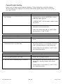
General Trouble Shooting
Below are a few general trouble shooting guidelines. If after reading this section, the condition
does not change or the condition is not covered in this section, please contact Chart’s service team
at +1 408.371.4932.
Condition: The UltraDoser safety relief valve is venting.
Possible Causes
Actions
The pressure of the LN2 supply is greater than 50
Check the pressure of the LN2 supply. If the
psi (3.44 bar).
supply pressure is greater than 50 psi (3.44 bar),
reduce the supply pressure.
**IMPORTANT: A dewar can be vented to reduce
the pressure.
The vent is obstructed.
Check the UltraDoser unit vent. If the vent is
obstructed, clear the obstruction.
If the vent is obstructed with ice, contact Chart’s
service team at +1 408.371.4932.
Condition: Liquid is coming out of the UltraDoser vent.
Possible Causes
Actions
The LN2 supply pressure is too high.
Lower LN2 supply pressure to 22 psi (1.5 bar) or
lower.
Ice has developed inside the unit, causing the
internal float valve to malfunction.
The UltraDoser unit must be drained of liquid,
allowed to warm up over a minimum of 24 hours
with a continuous purge of warm nitrogen gas.
Contact Chart’s service team at +1 408.371.4932
for a detailed procedure.
Condition: Liquid is coming out of the UltraDoser dosing head even though the valve is shut close.
Possible Causes
Actions
The LN2 supply pressure is too high.
Reduce the LN2 supply pressure.
The valve seat is contaminated (ice or particles).
The UltraDoser unit must be drained of LN2, The
dosing valve assembly must be removed and
cleaned.
Contact Chart’s service team at +1 408.371.4932
for a detailed procedure.
www.chartdosers.com
PN 1903
Page 31 of 35
Condition: No liquid from the UltraDoser dosing head.
Possible Causes
Actions
There is insufficient liquid inside the UltraDoser
Check the level of LN2. If the level is empty or
unit.
low, open the supply valve on the Dura-Cyl dewar.
The unit is disabled.
Switch the Dose Enable switch on the controller to
the “1” position.
The nozzle is frozen shut.
Remove, clean, and re-install the nozzle (see page
30).
There is insufficient GN2 to the dosing head valve.
Check the level of GN2 at the source. If the level
is empty or low, replace.
The speed sensor is not functioning.
Check the speed sensor is operating correctly and
is sending a signal to the controller.
5. Condition: The dosing valve alarm is displayed on the SC350c controller.
Possible Causes
Actions
The dosing valve assembly is not moving.
Check the pneumatic pressure There must be more
than 60 psi (4.14 bar) to have the dosing valve
function correctly.
Check the confirm sensor for correct placement.
7. Condition: The SC350c controller is in speed compensated mode but is missing bottles (or containers).
Possible Causes
Actions
The container sensor is not detecting a container.
Check sensor connections. If necessary, replace
sensor.
The speed sensor has been dislodged.
Check speed sensor connections.
The speed sensor has malfunctioned.
Replace speed sensor.
**IMPORTANT: The UltraDoser unit will continue to dose even if there is a speed sensor fault.
The SC350c controller displays the last known speed and compensates per that speed.
www.chartdosers.com
PN 1903
Page 32 of 35
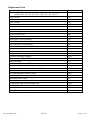
Replacement Parts
Part Description
Injection Unit Spare Parts Kit
Includes PNs: 102, 103, 104, 105C, 106C, 141, 362, and 535
0.040” Nozzle
0.050” Nozzle
0.060” Nozzle
Vent Heater Assembly (no cable included)
Vent Heater Cable
Dosing Head Heater (no cable included)
Nozzle (Dosing Head) Heater Cable
10 Micron Inlet Filter
10’ CryotechFlex Fill Hose
Dosing Stem (Valve) Assembly
Nozzle Tool – 4mm Hex Nut Driver
Controller Power Cord Assembly
Solenoid Valve Spare Assembly
12mm Sensor Support Hardware: Mount (for PN 336)
Complete Sensor Bracket Assembly UltraDoser
Bottle Detect Sensor (12mm Ultrasonic Sensor PNP)
Controller Mounting Assembly
Controller Assembly – SC350c
Gauge Assembly
User Manual, UltraDoser SC350c
UltraDoser Body
Speed Sensor (12mm Inductive Proximity PNP)
Speed Sensor support bracket (for PN 2807)
EP (EletroPneumatic) Head Assembly
Distribution Block
Distribution Block Cable
Confirm Sensor and Cable - UltraDoser
Solenoid Valve and Cable Assembly PNP
Liquid Gasket, 625
Distribution Block Cable, 12’ Extension
Timing/Container Sensor Cable
www.chartdosers.com
PN 1903
Part Number
567
102
103
104
105C
105C.01
106C
1411
108
123
141
362
410
535
584
1422
336
2384
2810A
133
1903
15171
2807
2779
1005
571
573
1201
1202
C6208
209
2440.16
Page 33 of 35
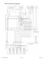
SC350c Controller Wiring Diagram
www.chartdosers.com
PN 1903
Page 34 of 35
Warranty
All sales of Liquid Nitrogen Dosing Systems (“LN2 Dosing Systems”) from Chart Inc. ("Chart") to
the purchaser are subject to all applicable Chart standard terms and conditions in effect at the time
of sale, unless otherwise agreed in writing by an authorized representative of Chart. In addition to
the warranty stated in Chart’s Standard Terms and Conditions of Sale, Chart warrants to the
original purchaser of Chart manufactured LN2 Dosing Systems that for one (1) year after the date
of shipment to the original purchaser said Chart manufactured LN2 Dosing System will maintain
all vacuum and performance standards for said LN2 Dosing System as published by Chart on the
date of invoice.
Purchaser agrees that as a pre-condition to any Chart warranty obligation hereunder, purchaser
shall fully inspect the LN2 Dosing System immediately upon delivery to purchaser and shall give
Chart written notice of any claim or purported defect within ten (10) days after receipt of the LN2
Dosing System. As a further pre-condition to any Chart warranty obligation hereunder, purchaser
shall return said purportedly defective LN2 Dosing System, freight prepaid, to the plant of the
manufacturer within thirty (30) days after receipt of the LN2 Dosing System. Chart shall inspect the
returned LN2 Dosing System, and, if said LN2 Dosing System is found defective, shall, at Chart’s
option as purchaser’s sole and exclusive remedy, either (i) repair or replace such LN2 Dosing
System or any defective component or part thereof which proves to be defective, or (ii) refund the
net purchase price paid by the original purchaser. Alterations or repairs by others or operation of
such LN2 Dosing System in a manner inconsistent with Chart accepted practices and all operating
instructions, unless preauthorized in writing by Chart, shall void this warranty. This warranty does
not extend to defects caused by the effects of normal wear and tear, erosion, corrosion, fire, or
explosion.
Chart’s sole and exclusive liability under this Warranty is to the original purchaser and shall not
exceed the lesser of the cost of repair, cost of replacement, or refund of the net purchase price paid
of the LN2 Dosing System by the original purchaser. Chart is not liable for any other losses,
damages, or costs of delays, including incidental or consequential damages. CHART
SPECIFICALLY MAKES NO WARRANTIES OR GUARANTEES, EXPRESS OR IMPLIED,
INCLUDING THE WARRANTIES OF MERCHANTABILITY OR FITNESS FOR A
PARTICULAR PURPOSE OR USE, OTHER THAN OR WHICH EXTEND THOSE
WARRANTIES EXPRESSED HEREIN. The original purchaser shall indemnify, defend and hold
Chart harmless from any third party claims as a result of the use, sale, or lease of the LN2 Dosing
System.
www.chartdosers.com
PN 1903
Page 35 of 35