1
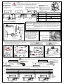
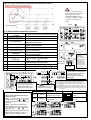
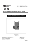
ME SERIES USER MANUAL
CONTENTS
1. Safety Precaution
2. Installation
3. Wiring and Grounding
4. C-200 Operation Panel Key Functions
5. Parameter Adjustment
6. Error Code List
7. 7 Segment LED Characters Compare Chart
HSVPMEU01-0
2008.03
EC Declaration of Conformity
We hereby declare that the following products:
AC servo motor--MA、MB、MD、ME、MH、MF series
are in conformity with the provision of the EC
directives as following :
-EC Low Voltage Directive (73/23/EEC)
-EC Electromagnetic Compatibility Directive
(89/336/EEC)
-EC Machinery Directive (98/37/EC)
Applied harmonized standards :
EN 60204-31 : Electrical equipment of industrial
machines. Particular requirements for sewing
machines, sewing units and sewing system.
EN 292-1 : Safety of machines.
EN 292-2 : Safety of machines, technical
guidelines and specifications.
EN 61000-6-2 : EMS for industrial environment.
EN 61000-6-3 : EMI for residential environment.
Declaration of Conformity for
Concentration Limits for Certain
Hazardous Substances
We hereby declare that the following products:
AC servo motor--MA、MB、MD、ME、MH、MF series
are complies with the following directives and
requirements :
1. European Union RoHS Directive (2002/95/EC) and
the concentration limits for certain hazardous
substances (2005/618/EC)
2. People’s Republic of China Electronic Business
Standard : Requirements for concentration limits for
certain hazardous substances in electronic
information products (SJ/T 11363-2006)
Our product itself (motor, control box) or its packing
materials and accessories (box, screws package,
user manual, sticker, label, print…etc.) or the
suppliers of parts and raw materials are all in
conformity with the provision of the European Union
RoHS Directive and People’s Republic of China
Electronic Business Standard to conform the
following concentration limits for the six hazardous
substances :
Hazardous
Substance
Permissible Values
Lead (Pb)
Mercury
Less than 240 ppm
(Hg)
Cadmium
Less than 800 ppm
(Cd)
Hexavalent
chromium (Cr
VI)
Polybrominated
Biphenyl (PBB)
Polybrominated
Diphenyl ether
(PBDE)
Less than
80 ppm
Please read this manual with sewing machine manual thoroughly and pay attention for
the following safety precaution.
․Installation and operation must be done by the trained personnel, also turn off the power switch and remove the plug
from outlet and wait for 5 minutes before any installation.
․This product is designed for the specific sewing machines and must not be used for other purposes.
․Only use the power voltage as described on the name plate of the ME motor and control box in ±10 % ranges.
※Attention : If the control box is AC 220V system, please don’t connect to the AC 380V power
outlet, otherwise the error will occur and motor is not functional. If that
happened, please turn off the power switch immediately and check the power
voltage. Continue supply the 380V power over 5 minutes might damage the
fuses (F1,F2) of EMI board and burst the electrolytic capacitors (C4,C5) of power
board and even might endanger the person safety.
․In order to prevent abnormal operation, keep the product away from the high frequency machines.
․Don’t operate in direct sun light、outdoors area and the room temperature is 45°C above or 5°C under.
․Don’t operate near the heater、dew area and the humidity is 30 % less or 95% more.
․Don’t operate in dusty、evaporate、combustible gas area, and stay away from corrosive material.
․Don’t apply heavy objects or excessive force on the power cord, also don’t bend or pull the power cord.
․Power cord must keep 3 cm or above distance away from the V-belt and the pulley.
․In order to prevent the static interference and current leakage, all grounding works must be done properly.
․After power on the machine for the first time, use low speed to operate and check the correct rotation direction.
․During machine operation, don’t touch any moving parts.
․All moving parts must have protective device to avoid the body contact and objects insertion.
․Maintenance and repair must be done by the properly trained technician, also all the spare parts for repair must be
approved or supplied by the manufacturer.
․Don’t use any objects or force to hit or ram the product.
Danger and caution signs
Risks that may cause personal injury or risk to the machine are marked with this
symbol in the instruction manual.
This symbol indicates electrical risks and warnings.
Limited Warranty
Less than 800 ppm
Warranty period of this product is 1 year from purchasing, or 18 months from our manufacturing date.
Less than 800 ppm
Warranty Detail
Less than 800 ppm
Any trouble found within warranty period under normal use condition in conformance with this manual, it will be
repaired free of charge. Repair will be chargeable in the following cases even if within warranty period :
*The concentration of lead in the lead-free process
for PCB shall be less than 800 ppm.
*For packing materials shipped with our products
or parts, the hazardous substances shall be 80
ppm or less in sum of Pb+Hg+Cd+Cr VI.
H. S. Machinery. Co., Ltd.
Mr. C. H. Tai
Plant Manager
1. Safety Precaution :
1. Inappropriate use include: wrong connecting high voltage, wrong application, disassemble, repair, modification by
incompetent personnel, or operate the product without the precaution, or operate the products out of its
specification range. Insert odd objects or liquids into the product.
2. Damage by fire, Earth quake, lighting, wind, flood, salt corrosive, moisture, abnormal power voltage and any other
damage cause by the natural disaster or by the inappropriate environments.
3. Dropping after purchase, or damage in transportation by customer himself. (or by customer’s shipping agency)
Note : We put our best effort and mind in testing and manufacturing for assuring the quality and reliable of this product.
But it is possible this product can still be damaged due to external magnetic interference and electronic static or
noise or unstable power source more than expected; therefore the grounding system of operate area must be
well-connected to this product and it’s also recommended to install a failsafe device. (such as residual current
breaker).
decrease
Caution :
For person safety, turn off the power switch and remove
the power plug from outlet before any adjustment.
2. Installation :
ME installation
a). Install the motor and
control box under
the table
b). Install the pedal with
speed control unit.
ME series
Synchr
onizer
Stopper
To control box
C-200 operation panel
C
c). Install the V-Belt on the motor
and machine pulley, then adjust Components of speed control unit :
see figure
the belt to its appropriate
A:Spring for toeing forward force
tension.
Pedal
Hand wheel
Hexagonal
screw
B
Speed control unit
adjustment
B:Bolt for heeling backward force
decrease
C:Pedal arm
D:Pitman rod for pedal
Belt
Synchronizer installation
increase
A
increase
Term of adjustment
Adjustment result
1
Toeing forward
Force adjustment
Spring A move to right = force increased
2
Heeling backward
force adjustment
Bolt B turn
Bolt B turn
3
Pedal stroke
adjustment
Rod D secure at right = stroke is longer
Rod D secure at left = stroke is shorter
Spring A move to left = force decreased
= force decreased
= force increased
Synchronizer Adjustment ( Please open the top cover first )
Needle up position : Rotate the machine pulley to reach mechanical needle up position and turn the
photo disc (A) until its red mark is aligned with the red mark on the bearing cover
plate.
Needle down position : Rotate the machine pulley to reach mechanical needle down position and turn
the photo disc (B) until its blue mark is aligned with the red mark on the
bearing cover plate.
Note: Instruction above is the standard adjustment. If you feel the position wasn’t accurate, please do
the fine tuning by yourself.
Mounting the Synchronizer onto the
flange of hand wheel and match the
stop groove of the synchronizer with
the stopper of the machine head
then tighten and secure 2 hexagonal
screws of the synchronizer rotor,
then connect the synchronizer cable
to the control box.
Note : Stopper type and location
might be varied, depend by
the machine model.
Setting screw
..
Bearing cover plate
Photo disc (A)
Photo disc (B)
(Operation panel install location might be varied depend by the bracket type and sewing machine model.)
a). Mount the operation panel on the bracket and secure
the 3 screws show in the diagrams.
b). Loosen screws A B in the back
of machine head and install the
bracket with the operation panel.
c). After installation secure the
screws A B and connect the
cable to the control box
A
B
C
D
C - 200
+
P
A B
S
D
P1
PD
_
A
3. Wiring and Grounding :
B BB
A C C
D
B
Caution :
Green / Yellow wire is for grounding, and all grounding works must be done properly.
Single phase ( AC220V )
To control box
C
Green / Yellow
(ground wire)
Brown wire
Blue wire
Three phase ( AC380V )
To control box
Brown wire
Black wire
Blue wire
Green / Yellow
(ground wire)
When multiple 1Φ / 220 V motors are connected to a 3 Φ / 220 V power source, take caution for the load
balance of each R, S, T. phase, see the following diagram :
R
S
T
PE
Grounding
system
.
D
How to connect a 1Φ / 220 V power from a 3 Φ / 380 V power source
Attention : Must have a neutral point layout
Caution : If the power source
does not have the neutral point,
then this 1Φ / 220 V servo
motor is not suitable for this
connection. Please ask supplier
to offer our 3Φ / 380 V servo
motor.
Neutral point
Motor
Motor
Motor
6
3
4. C-200 Operation Panel Key Functions :
Parameter enter /
increment
Enter parameter mode / parameter NO. increment
2
Parameter value / save
Enter value area / Save key / Enter multi-function
3
F multi-function
4
Start back-tacking
5
End back-tacking
6
LED display
7
Constant-stitch sewing
8
Bar-tacking
9
Power ON LED
10
A、B、C、D area value
adjust key
1
11
9
Front
Grounding system
1
4
7
2
5
8
11
12
10
13
Definable multi-function key
Stitches for A、B section, 15 stitches max. /
Parameter NO. increment
Stitches for C、D section, 15 stitches max. /
Parameter NO. decrement
Parameters / functions / A、B、C、D area value
Back
9
13 sections max. (P1~PD section), 250 stitches
max. for each section.
15 stitches max. for A、B、C section, 15 turns max.
(D area) for bar-tacking.
14
Power ON LED / Warning LED
= increment /
12
Auto
13
Trimming
14
External LED light socket
= decrement
For external LED light, its ON or OFF state can be
memorized by the operation panel.
External LED light switch
0V
12V
1
2
External LED
wiring layout
Auto-function for constant-stitch sewing.
DC 12V
LED light
Trimming function ON or OFF
.
After function selected, press the
F key under the normal mode to
use the function. The operation
panel will memorized the
selected function and its state
automatically.
.
.
In normal mode, press S
key for 2 sec. to access the
multi-function select area.
Select any function to use.
5. Parameter Adjustment :
How to enter parameter value area to
adjust the value :
Step 1:Enter any parameter mode show
at right side, then use
or
key to
find the parameter NO. which need to be
adjusted.
Step 2:After find the parameter NO.,
Parameter mode
Operation
First display
Range for parameter
Level 1
Mode A
On normal mode, press
and hold P key for 2 sec.
.
Parameter from # 001
~ 046
Level 2
Mode B
Hold P key and power ON
at same time.
.
Parameter from # 001
~ 122
C
press the S key to enter the parameter
value area, then use
or
key to
adjust the value.
Note : After the value adjusted, press the
S key to save the setting, or else the
setting will be lost after power OFF.
F0. NOP=No function.
F1. FK=Thread clamp (press F key to switch the function ON/OFF)
F2. WON=Wiper (press F key to switch the function ON/OFF)
F3. NUD=Needle up or down (press F key to switch the needle up or
down)
F4.SLOW=Slow start (press F key to switch the function ON/OFF)
F5. USW=Needle up switch (press F key to lift the needle to up position
F6. CRS=Counter reset (press F key under the counter mode to reset
the counter.
The
key under the D
area is the selection key for
F multi-function. (F0~F6)
+
D
Note : After
install the
external LED
light, make sure
that the LED and
its cable are
firmly secured to
avoid the LED or
its cable fall into
the running motor
or machine.
The socket for external DC 12V LED light.
F multi-function key adjustment
A B
.
C - 200
A
P
B
C
D
C - 200
.
F
+
A B
A
P
P1
PD
+
A B
C
S
A C C
D
C - 200
A
+
A B
B
C
D
P1
PD
D
C
P
P1
D
C - 200
A
.
F
P
A C C
D
S
S
A C C
+
A B
P1
PD
_
B BB
B BB
D
A
.
+
A B
P1
PD
_
C
D
_
S
C - 200
F
B BB
.
F
P
D
_
B BB
D
C
PD
_
S
B
.
F
C
A C C
D
B
C
D
B BB
D
C
A C C
D
B
C
D
General parameter list
Parameter
【001.
Function Name
H】
【002.SLM】
【004. N】
【005. V】
【006. B】
【007. S】
【009. A】
【122. HL】
【014.SBT】
【015.SBA】
【016.SBB】
【017.SBN】
【021.EBT】
【022.EBC】
【023.EBD】
【024.EBN】
【032.BAR】
【033.BRC】
【034.BRN】
【010.ACD】
【038. PM】
【039. PS】
【040.WON】
【041. TM】
【075.SFM】
【063.FTP】
【064. FO】
【065. FC】
【066. FD】
【070.HHC】
Range
Description
Speed related parameter
50~9999 spm
Maximum sewing speed setting.
Maximum sewing speed
T=Soft start activate on next sewing after trimming.
Soft start mode selection
T/A
A=Soft start activate when pedal down.
Start back-tacking speed
50~8000 spm
Start back-tacking speed adjustments
End back-tacking speed
50~8000 spm
End back-tacking speed adjustments
Bar-Tacking Speed
50~8000 spm
Bar-tacking speed adjustments
Slow start speed
50~2000 spm
Slow start speed adjustments
Automatic constant-stitch sewing speed
50~8000 spm
Automatic constant-stitch sewing speed adjustments
The limit of the maximum sewing speed. (If【122. HL】
Upper limit of maximum speed
=3000, but【001. H 】= 4000, then the valid maximum
50~9999 spm
sewing speed is limited to 3000)
Back tacking related parameter
Start back-tacking function selection
ON / OFF
Start back-tacking turn ON or OFF
Setting stitches A of Start back-tacking
0~15 stitches
Start back-tacking stitches for A section
Setting stitches B of Start back-tacking
0~15 stitches
Start back-tacking stitches for B section
Setting turns of Start Back-tacking
0~4 turns
Start back-tacking turns
End back-tacking selection
ON / OFF
End back-tacking turn ON or OFF
Setting stitches C of End back-tacking
0~15 stitches
End back-tacking stitches for C section
Setting stitches D of End back-tacking
0~15 stitches
End back-tacking stitches for D section
Setting turns of End back-tacking
0~4 turns
End back-tacking turns
Bar-tacking selection
ON / OFF
Bar-tacking turn ON or OFF
Setting stitches of Bar-tacking
0~99 stitches
Bar-tacking stitches
Setting turns of Bar-tacking
0~15 turns
Bar-tacking turns
Constant stitch related parameter
Automatic sewing End back-tacking
ON / OFF
Auto end back-tacking after constant stitches sewing
Constant-stitch sewing selection
ON / OFF
Constant-stitch sewing turn ON or OFF
Stitches for each section of constant-stitch sewing
Setting stitches for section of
0~250 stitches
Constant-stitch sewing
(P1~PD sections, total13 sections)
Wiper & Trimmer related parameter
Wiper function selection
ON / OFF
Wiper turn ON or OFF
Trimmer function selection
ON / OFF
Trimmer turn ON or OFF
Safety switch
NO / NC
Safety switch
Presser foot related parameter
Selection for foot lifting solenoid
M/A
M=Magnetic type / A=Air type
Full-On time for foot lifting solenoid
0~990 ms
Solenoid pulling torque adjustment
Duty cycle time for foot lifting solenoid
10~90 %
Solenoid switching power adjustment.
Running-Delay time setting
0~990 ms
Delay time for presser foot
Cancel foot lifting at half-heeling pedal
ON / OFF
No foot lifting at half-heeling when turn ON
6. Error Code List :
Error code
Cause of the problem
Condition and solution (Repair and maintenance must be performed by a trained technician.)
1. Bad connection to the motor connector.
2. Synchronizer (sensor) signal error.
3. Machine locked or object stuck in the motor pulley.
4. Sewing material is too thick.
Motor and machine will be shutting down.
Please check the motor or motor connectors’ connection.
Please check the synchronizer (sensor) and its signal.
Please check machine head to see if any objects stuck in the motor pulley, or
machine does not rotate smoothly.
ER0. 12
Power on, no synchronizer signal was detected or
synchronizer is not connected.
Automatic starts the clutch mode.
Please check the synchronizer and its connection.
ER0.16
1. Safety switch is defected or bad connection.
2. Parameter【075. SFM】setting not match the machine
head model.
Motor stopped
Please check the safety switch.
Please check parameter【075. SFM】setting, make sure it match machine
head’s safety switch.
ER0. 7
7. 7 Segment LED Characters Compare Chart :
Arabic Numerals
0
1
2
3
4
5
6
7
8
9
English Alphabet
A
B
C
D
E
F
G
H
I
J
K
L
M
N
O
P
Q
R
S
T
U
V
W
X
Y
Z
If you need the technical support, please contact your distributor or browse our website at http://www.hohsing.com