1
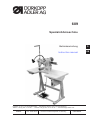
609
Spezialnähmaschine
Betriebsanleitung
D
Instruction manual
GB
Postfach 17 03 51, D-33703 Bielefeld • Potsdamer Straße 190, D-33719 Bielefeld
Telefon +49 (0) 521 / 9 25-00 • Telefax +49 (0) 521 / 9 25 24 35 • www.duerkopp-adler.com
Ausgabe / Edition:
10/2007
Änderungsindex
Rev. index: 01.0
Printed in Federal Republic of Germany
Teile-Nr./Part.-No.:
0791 609741
Alle Rechte vorbehalten.
Eigentum der Dürkopp Adler AG und urheberrechtlich geschützt. Jede, auch auszugsweise
Wiederverwendung dieser Inhalte ist ohne vorheriges schriftliches Einverständnis der Dürkopp Adler AG
verboten.
All rights reserved.
Property of Dürkopp Adler AG and copyrighted. Reproduction or publication of the content in any manner,
even in extracts, without prior written permission of Dürkopp Adler AG, is prohibited.
Copyright © Dürkopp Adler AG - 2007
Foreword
This instruction manual is intended to help the user to become familiar
with the machine and take advantage of its application possibilities in
accordance with the recommendations.
The instruction manual contains important information on how to
operate the machine securely, properly and economically. Observation
of the instructions eliminates danger, reduces costs for repair and
down-times, and increases the reliability and life of the machine.
The instruction manual is intended to complement existing national
accident prevention and environment protection regulations.
The instruction manual must always be available at the machine/sewing
unit.
The instruction manual must be read and applied by any person that is
authorized to work on the machine/sewing unit. This means:
–
–
–
Operation, including equipping, troubleshooting during the work
cycle, removing of fabric waste,
Service (maintenance, inspection, repair) and/or
Transport.
The user also has to assure that only authorized personnel work on the
machine.
The user is obliged to check the machine at least once per shift for
apparent damages and to immediatly report any changes (including the
performance in service), which impair the safety.
The user company must ensure that the machine is only operated in
perfect working order.
Never remove or disable any safety devices.
If safety devices need to be removed for equipping, repairing or
maintaining, the safety devices must be remounted directly after
completion of the maintenance and repair work.
Unauthorized modification of the machine rules out liability of the
manufacturer for damage resulting from this.
Observe all safety and danger recommendations on the machine/unit!
The yellow-and-black striped surfaces designate permanend danger
areas, eg danger of squashing, cutting, shearing or collision.
Besides the recommendations in this instruction manual also observe
the general safety and accident prevention regulations!
General safety instructions
The non-observance of the following safety instructions can cause
bodily injuries or damages to the machine.
1. The machine must only be commissioned in full knowledge of the
instruction book and operated by persons with appropriate training.
2. Before putting into service also read the safety rules and
instructions of the motor supplier.
3. The machine must be used only for the purpose intended. Use of
the machine without the safety devices is not permitted. Observe all
the relevant safety regulations.
4. When gauge parts are exchanged (e.g. needle, presser foot, needle
plate, feed dog and bobbin) when threading, when the workplace is
left, and during service work, the machine must be disconnected
from the mains by switching off the master switch or disconnecting
the mains plug.
5. Daily servicing work must be carried out only by appropriately
trained persons.
6. Repairs, conversion and special maintenance work must only be
carried out by technicians or persons with appropriate training.
7. For service or repair work on pneumatic systems, disconnect the
machine from the compressed air supply system (max. 7-10 bar).
Before disconnecting, reduce the pressure of the maintenance unit.
Exceptions to this are only adjustments and functions checks made
by appropriately trained technicians.
8. Work on the electrical equipment must be carried out only by
electricians or appropriately trained persons.
9. Work on parts and systems under electric current is not permitted,
except as specified in regulations DIN VDE 0105.
10. Conversion or changes to the machine must be authorized by us
and made only in adherence to all safety regulations.
11. For repairs, only replacement parts approved by us must be used.
12. Commissioning of the sewing head is prohibited until such time as
the entire sewing unit is found to comply with EC directives.
13. The line cord should be equipped with a country-specific mains
plug. This work must be carried out by appropriately trained
technicians (see paragraph 8).
It is absolutely necessary to respect the safety
instructions marked by these signs.
Danger of bodily injuries !
Please note also the general safety instructions.
Content
page:
Preface and general safety instructions
Part 1: Operating Instructions class 609
(Edition 10/2007)
1.
Product description . . . . . . . . . . . . . . . . . . . . . . . . . . . . . . . . . . . . . . . . . . . .
5
2.
Designated use . . . . . . . . . . . . . . . . . . . . . . . . . . . . . . . . . . . . . . . . . . . . . . .
5
3.
Subclasses . . . . . . . . . . . . . . . . . . . . . . . . . . . . . . . . . . . . . . . . . . . . . . . . . .
6
4.
Optional equipments
. . . . . . . . . . . . . . . . . . . . . . . . . . . . . . . . . . . . . . . . . . .
6
5.
Technical Data . . . . . . . . . . . . . . . . . . . . . . . . . . . . . . . . . . . . . . . . . . . . . . . .
7
6.
6.1
6.2
6.3
6.4
6.5
6.6
6.7
6.8
6.9
Operation
Threading the needle thread . . . . .
Adjusting the needle thread tension
Opening the needle thread tensioner
Winding on the hook thread. . . . . .
Fitting the hook-thread bobbin . . . .
Adjusting the hook-thread tension .
Inserting and changing the needle .
Adjusting the sewing foot stroke . .
Adjusting the sewing foot pressure .
.
.
.
.
.
.
.
.
.
.
.
.
.
.
.
.
.
.
.
.
.
.
.
.
.
.
.
.
.
.
.
.
.
.
.
.
.
.
.
.
.
.
.
.
.
.
.
.
.
.
.
.
.
.
.
.
.
.
.
.
.
.
.
.
.
.
.
.
.
.
.
.
.
.
.
.
.
.
.
.
.
.
.
.
.
.
.
.
.
.
.
.
.
.
.
.
.
.
.
.
.
.
.
.
.
.
.
.
.
.
.
.
.
.
.
.
.
.
.
.
.
.
.
.
.
.
.
.
.
.
.
.
.
.
.
.
.
.
.
.
.
.
.
.
.
.
.
.
.
.
.
.
.
.
.
.
.
.
.
.
.
.
.
.
.
.
.
.
.
.
.
.
.
.
.
.
.
.
.
.
.
.
.
.
.
.
.
.
.
.
.
.
.
.
.
.
.
.
.
.
.
.
.
.
.
.
.
.
.
.
.
.
.
.
.
.
.
.
.
.
.
.
.
.
.
.
.
.
.
.
.
.
.
.
.
.
.
.
.
.
.
.
.
.
.
.
.
.
.
.
.
.
.
.
.
.
.
.
.
.
.
.
.
.
.
.
.
.
.
.
.
.
.
.
.
.
.
.
.
.
.
.
.
.
.
.
.
.
8
8
9
10
11
12
13
14
15
7.
7.1
7.2
7.2.1
7.2.2
7.2.3
Control unit and operating panel
General . . . . . . . . . . . . . . . . . . . . .
Sewing drive HoHsing HVP 70-4-ED-2-CE
Control unit keys (sewing mode) . . . . . . .
Operating panel keys (Type C300) . . . . .
Changing the parameter values . . . . . . .
.
.
.
.
.
.
.
.
.
.
.
.
.
.
.
.
.
.
.
.
.
.
.
.
.
.
.
.
.
.
.
.
.
.
.
.
.
.
.
.
.
.
.
.
.
.
.
.
.
.
.
.
.
.
.
.
.
.
.
.
.
.
.
.
.
.
.
.
.
.
.
.
.
.
.
.
.
.
.
.
.
.
.
.
.
.
.
.
.
.
.
.
.
.
.
.
.
.
.
.
.
.
.
.
.
.
.
.
.
.
.
.
.
.
.
.
.
.
.
.
.
.
.
.
.
.
.
.
.
.
.
.
.
.
.
.
.
.
.
.
.
.
.
.
.
.
.
.
.
.
.
.
.
.
.
16
16
17
18
19
8.
Sewing . . . . . . . . . . . . . . . . . . . . . . . . . . . . . . . . . . . . . . . . . . . . . . . . . . . . .
19
9.
9.1
9.2
Maintenance
Cleaning and testing . . . . . . . . . . . . . . . . . . . . . . . . . . . . . . . . . . . . . . . . . . . . .
Lubrication . . . . . . . . . . . . . . . . . . . . . . . . . . . . . . . . . . . . . . . . . . . . . . . . . . .
23
24
.
.
.
.
.
.
.
.
.
.
.
.
.
.
.
.
.
.
.
.
.
.
.
.
.
.
.
GB
1.
Product description
The DÜRKOPP ADLER 609 is a single needle double lockstitch
cylinder arm machine for attaching and basting works on jackets,
coats, suit jackets and the like.
The machine is equipped with an integrated DC direct drive and an
operating panel for the programming of the sewing parameters.
·
·
·
·
·
·
·
·
·
·
Double lockstitch cylinder arm machine
Integrated direct current direct drive
Easy operating by means of the external operating panel.
Automatic thread trimmer under the throat plate.
Small horizontal hook.
Integrated winder for the bobbin thread.
Simple pulling of the thread when moving the material through
eccentric actuated tension release.
Easy processing of materials up to 19 mm thick.
Simplified inserting of the material through the reverse function of
the needle.
Easy handling through cylindrical covering on the free arm.
GB
2.
Designated use
The 609 is a special sewing machine designed for sewing light to
medium-heavy material. Such material is generally made of textile
fibers, but it may also be leather. It is used in the clothing, footwear
and leatherwear industries as in domestic and motor-vehicle
upholstery.
This special sewing machine can also be used to produce so-called
technical seams. In this case, however, the operator must assess the
possible dangers which may arise (with which DÜRKOPP ADLER AG
would be happy to assist), since such applications are on the one hand
relatively unusual and, on the other, so varied that no single set of
criteria can cover them all.
The outcome of this assessment may require appropriate safety
measures to be taken.
Generally only dry material may be sewn with this machine. The
material may be no thicker than 9 mm when compressed by the
lowered sewing feet. The material may not contain any hard objects,
since if it does the machine may not be operated without an
eye-protection device. No such device is currently available.
The seam is generally produced with textile-fibre sewing thread of
gauge up to 80/3 Nm. Before using any other thread the possible
dangers arising must be assessed and appropriate safety measures
taken if necessary.
This special sewing machine may be set up and operated only in dry,
well-maintained premises. If the sewing machine is used in premises
which are not dry and well-maintained it may be necessary to take
further precautions (which should be agreed in advance - see EN
60204-31:1999).
5
As manufacturers of industrial sewing machines we proceed on the
assumption that personnel who work on our products will have
received training at least sufficient to acquaint them with all normal
operations and any possible hazards which these may involve.
3.
4.
Subclasses
609-100101
Single needle double lockstitch free-arm machine for
manual material feed.
Order No.
MG55 400344
Optional equipment
Stand
with table plate 1060x550
Table extension
for accomplishing attaching work flat, table top
1400 x 550mm
Sewing lamp
with flexible arm, lamp 12V/20W
Table clamp
for clamping the sewing lamp onto the table plate.
Add-on kit socket for the sewing lamp
for the electrical connection under the table top.
Optional equipments
0609 590014
9822 510026
9822 510027
9870 001021
Further available documents concerning the class 609
0791 609801
Parts List
0791 609641
Service Instructions
6
5. Technical data
Rated noise value Lc:
Workplace-related emission value in accordance with DIN
45635-48-A-1-KL2
Lc = xx dB (A)
Class: 609
Stitch length: manual
Sewing foot stroke: 15 mm
Speed: 800 [min -1 ]
Material: double Skai 1,6 mm 900 g/m 2 DIN 53352
Needle system:
134-35
Needle thickness (depending on the equipment no.)
[Nm]
80 - 100
Max. thread thickness:
[Nm]
80/3
Speed:
- max.
- ex factory
[min -1 ]
[min -1 ]
1000
800
Max. stitch length:
manual
Max. sewing foot stroke:
[mm]
19,5
Max. clearance under the sewing foot with the needle bar
positioned:
[mm]
20
Rated voltage:
GB
1 x 220-240V, 50/60HZ
Dimensions:
- Stand MG 55-3
[mm]
1540 x 1060 x 550
Working height:
- Stand MG 55-3
[mm]
750 - 900
Weight (only the machine head)
[KG]
32
7
6.
Operation
6.1 Threading the needle thread
Caution: Danger of injury!
Turn off the main switch !
The needle thread may only be threaded with the sewing machine
switched off.
2
1
6.2 Adjusting the needle thread tension
Pre-tension
In order to guarantee a safe function of the thread trimmer with the
class 609, it is necessary that the needle thread is under residual
tension when the main tensioner 2 is open.
The residual tension is generated by the pre-tensioner 1.
The pre-tensioner 1 determines the length of the needle thread end
after the thread trimming.
The pre-tension 1 should be set lower than the main tension 2.
– Adjust the pre-tension 1 by turning the knurled nut.
– After major changes on pre-tension 1, adjust the main tension 2
accordingly.
Main tension
The main tensioner 2 should be set to the minimum possible tension.
The looping of the threads must be in the center of the material (see
fig. a).
With thin material excessive thread tension can cause unwanted
gathering and thread breakage.
– Adjust the main tensioner 2 so that the stitches are uniform.
8
Fig. A
Correct thread loop in the center of the
material
Fig. B
Needle-thread tension too low
or
hook-thread tension too high
Fig. C
Needle-thread tension too high
or
hook-thread tension too low
6.3 Opening the needle thread tensioner
GB
2
1
Electromagnetically
The main tensioner 2 will be opened electromagnetically:
·
During thread trimming via solenoid 1.
Mechanically
The main tensioner 2 will be opened mechanically:
·
Through an eccentric on the arm shaft, each time the thread lever
reaches a point 2 mm after the upper dead center (UDC).
9
6.4 Winding on the hook thread
4
–
–
–
–
–
–
–
10
3
2
1
Thread the hook thread as shown in the picture above.
Fit the bobbin 3 on the bobbin-winder shaft 2.
Wind approximately five coils of hook thread anti-clockwise onto
the bobbin core.
Cut the thread end with the knife and clamp it.
Press the release lever 1 against the bobbin.
The bobbin-winder wheel is pressed against the driving wheel of
the arm shaft.
Adjusting the tension 4.
The hook thread should be wound on with minimum tension.
Sewing.
The release lever 1 terminates the process automatically as soon
as the bobbin is full.
6.5 Fitting the hook-thread bobbin
3
1
2
6
5
4
1
Caution: Danger of injury!
Turn off the main switch !
The hook-thread bobbin may only be changed with the machine
switched off.
GB
Remove the empty bobbin
– Turn the hand wheel, until the needle bar has reached its highest
position.
– Open the cap 2 on the arm cover.
– Raise bobbin-housing flap 1.
– Remove the upper part of the bobbin-housing 3 together with the
bobbin.
– Remove the empty bobbin from the upper part of the
bobbin-housing 3.
Threading the hook thread
– Place the full bobbin 4 in the upper part of the bobbin-housing 3.
The bobbin 4 must rotate in the direction of the arrow when the
thread is pulled.
– Draw the hook thread through the slit 5 under the tension spring 6.
– Pull approximately 8 cm of the hook thread out of the upper part of
the bobbin housing 3.
– Replace the upper part of the bobbin housing 3 again.
– Close the cap 2.
11
6.6 Adjusting the hook-thread tension
2
3
1
5
4
Adjusting the braking spring 1
The braking spring 1 prevents the idle motion of the bobbin when the
machine halts or during a jerky drawing of the hook thread for example
when pulling the thread of the thread-pulling knife.
– Unscrew the adjustment screw 5 until no tension remains in the
tension spring 3.
– Adjust the braking spring 1 with adjustment screw 4.
The braking force is correctly adjusted if the braking spring 1
is approx. 1 mm above the surface 2.
Adjusting the tension spring 3
– Adjust the tension spring 3 with adjustment screw 5.
To increase the hook-thread tension = turn screw clockwise
To decrease the hook-thread tension = turn screw anti-clockwise
For stitch formation see sketch on page 9.
12
6.7 Inserting and changing the needle
1
2
3
Caution: Danger of injury!
Turn off the main switch !
The needle may only be changed with the sewing machine
switched off.
GB
–
–
–
–
Turn the handwheel, until the needle bar 1 has reached its highest
position.
Loosen screw 2.
Pull the needle downwards out of the needle bar 1.
Push in the new needle into the hole of the needle bar 1 until it
stops.
ATTENTION!
When viewed from the operator side, the needle scarf 1 must point
towards the back of the machine (see sketch).
–
Tighten screw 2.
ATTENTION!
When changing to another needle size, the distance between hook and
needle must be readjusted (see service instructions).
Ignoring the above mentioned hint can cause the following mistakes:
·
·
When inserting a thinner needle:
Missed stitches
Damage of the thread
When inserting a thicker needle:
Damage of the hook tip and the needle
13
6.8 Adjusting the sewing foot stroke
3
2
1
Caution: Danger of injury!
Turn off the main switch !
The sewing foot stroke may only be adjusted with the machine
switched off.
The height of the sewing-foot stroke is determined by the position of
connecting rod 1.
Adjusting the sewing foot stroke
– Loosen the nut 3 on the back of the machine arm.
– Shift the connecting rod 1 within the shifting lever 2.
Connecting rod completely at the top = maximum sewing foot
stroke (20 mm)
Connecting rod completely at the bottom = minimum sewing foot
stroke (10 mm)
– Tighten the nut 3.
14
6.9 Adjusting the sewing foot pressure
max 25 mm
2
–
–
–
1
Loosen the counter nut 1.
The required sewing foot pressure can be adjusted with screw 2.
To increase the sewing foot pressure = turn screw 2 clockwise.
To decrease the sewing-foot pressure = turn screw 2 anti-clockwise.
Tighten the counter nut 1.
ATTENTION!
The set screw 2 shall not be screwed out more than 25 mm.
15
GB
7.
Control unit and operating panel
ATTENTION!
These operating instructions give the key functions and describe how
operator-level parameter values are changed by the operator.
For a detailed description of the control unit, please consult the enclosed
current issue of the operating manual of the motor manufacturer.
7.1 General
For the programming and the entering of sewing parameters, use the
function keys of the control unit and the operating panel.
These operating instructions give an overview of the basic functions
and the operating elements of the control unit and the operating panel.
Further information for the programming are described in the manual of
the motor manufacturer.
An operating manual of the motor manufacturer is enclosed with each
machine. If needed the manual can also be downloaded in further
languages from the website of the DÜRKOPP ADLER AG.
RESET
If the control unit is hopelessly out of adjustment, this function allows
the technician to reset all adjusted values to their default (ex factory)
settings.
The function is described in the manual of the motor manufacturer!
7.2 Sewing drive HoHsing HVP 70-4-ED-2-CE
The English version of the manual for the HoHsing HVP 70-4-ED-2-CE
sewing drive is enclosed with each machine.
If needed the manual can also be downloaded in further languages
from the website of the DÜRKOPP ADLER AG:
www.duerkopp-adler.com.
16
7.2.1
Control unit keys (sewing mode)
If the operating panel C300 is connected, the setting done through the
operating panel will have higher priority than settings done on the
control unit.
Switch free sewing**/
tacking / programmed
seam segment
Bartacking seam begin ON/ OFF
Programming key
Bartacking seam end* ON/OFF
Needle position top / bottom
at machine stop
Automatic sewing foot lifting*
after the thread trimming
ON / OFF
Softstart
ON / OFF
Automatic sewing foot lifting
after machine stop
UP / DOWN
Indicator for the motor’s
sense of rotation
Display for the number
of backtack stitches set
GB
Setting the stitch number
(Range 0 - F)
* A = 10 Stitches…
* B = 15 Stitches ....
*
Function disabled with this machine.
** Essentially the setting “free sewing” will be used with this
machine.
17
7.2.2
Operating panel keys (Type C300)
Explanation of the important function keys for the operation of the
class 609:
B
Initial bartack.
For the class 609, programming of a given number B of start stitches.
Selection of the stitch setting A-B-C-D or E-F or G-H
Setting and displaying the stitch settings A-H
Thread trimming ON / OFF
Needle position setting UP / DOWN
Free sewing
One stitch basting ON / OFF
18
7.2.3
Changing the parameter values
For checking purposes or after a reset the parameter values must be
set according to the parameter sheet (Part No. 9800 370001 PB40)
enclosed in the accessories.
If required, the current parameter sheet can be downloaded from the
website of the DÜRKOPP ADLER AG within the download area:
www.duerkopp-adler.com.
The setting of the parameter is described in the manual provided with
the sewing drive.
8.
Sewing
GB
Caution: Danger of injury!
Please proceed very cautiously, due to the high sewing foot stroke
(up to 19,5 mm) and the related increased danger of injury !
This description is based on the following assumptions:
– The main switch is turned on.
The following functions are set at the operating panel:
– Initial bartack: 3 preset attaching stitches
– The needle reverse function is set in the control parameters.
– The needle position setting is up.
– The thread trimmer is switched on.
– The last sewing process was completed with thread cutting.
19
Operating and function sequence:
Sewing process
Prior to sewing
Starting position
Position material
for starting the seam.
Operation / explanation
-
Pedal in rest position
The machine is at a halt.
Needle up
Sewing foot in highest position
- Place the material under the sewing foot
At the seam start
Sewing
Press the key
(bartack/attaching stitches)
of the
operating panel.
LED ON: Function bartack/attaching stitches ON.
LED OFF: Function bartack/attaching stitches OFF.
B
One stitch basting
with attaching stitches
- Prerequisite: on the operating panel
the
key has its LED ON
B
- Prerequisite: on the operating panel
the key (one stitch basting)
has its LED ON
- Push the pedal forwards.
- The machine sews attaching stitches
with the bartack speed
- During the attaching of the material
the machine should be fed slightly.
- After attaching, the machine stops
with the thread lever in upper position with
the thread tension open (even if the pedal is
pressed continuously, only the attaching
stitches will be sewn).
- Each time the pedal is pushed forward,
a single stitch will be sewn no matter
how long the pedal is pushed forward.
It is possible to pull any length of
single stitch.
Disabling the one stitch basting function
is only possible after the thread trimming.
Sewing continuous seam
with attaching stitches
- Prerequisite: on the operating panel
the
key has its LED ON
B
- Prerequisite: on the operating panel
the key (one stitch basting)
has its LED OFF
- Push pedal forwards and keep it pushed.
- The machine sews attaching stitches
with the bartack speed, then continues
at the speed of rotation set by the pedal.
- Feed the material manually
20
Sewing continuous seam
without attaching stitches
- Prerequisite: on the operating panel
the
key has its LED OFF
B
- Prerequisite: on the operating panel
the key (one stitch basting)
has its LED OFF
- Push pedal forwards and keep it pushed.
- The machine sews at the speed of
rotation set by the pedal.
- Feed the material manually
Even during the continuous seam, it is
possible to sew a single stitch by pushing
briefly the pedal!
In mid-seam
(only valid with sewing
continuous seam)
Interrupt the sewing process
Resume the sewing process
- Release pedal (rest position).
The machine stops in the needle up position
- Each time that the pedal is pushed briefly
the machine execute exactly one stitch.
If you actuate the pedal longer
the machine will sew continuously.
- Push the pedal forwards. The sewing
machine sews at the speed of rotation
set by the pedal.
At the seam end
with thread trimming
- Push pedal backwards and keep it pushed.
- The thread will be cut
- Sewing foot in highest position
(reverse function)
The material can be removed.
without thread trimming
- Push pedal backwards and keep it pushed.
- Sewing foot in highest position
(reverse function)
- The material can be removed.
The threads must be cut manually
21
GB
Notes:
22
9.
Maintenance
Caution: Danger of injury!
Turn off the main switch !
Maintenance may only be carried out with the machine switched off!
Maintenance work must be carried out no less frequently than at the
intervals given in the tables (see ”operating hours” column).
Maintenance intervals may need to be shorter when processing
heavy-shedding materials.
9.1 Cleaning and testing
A clean machine is a trouble-free machine!
1
GB
Maintenance work
to be carried out
Machine head
- Remove lint, pieces of
thread and other debris
Explanation
-Places in special need of cleaning:
Operating
hours
8
- Clean the area under the needle plate
from lint, pieces of thread.
You can do it with an air blow gun.
- Area around the hook
- Clean under the bobbin braking spring 1 from
lint.
Lift the spring slightly for example with
a needle and blow it.
- Needle thread tensioner
- Thread trimmer
Sewing drive
- Check the condition and the
tension of the toothed belt.
It must be possible to depress the toothed belt
by about 10 mm when pressing it with a finger at
its mid-point.
160
23
9.2 Lubrication
Caution: Danger of injury!
Oil can cause skin eruptions.
Avoid protracted contact with the skin.
In the event of contact, thoroughly wash the affected area.
ATTENTION!
The handling and disposal of mineral oils is subject to legal regulation.
Deliver used oil to an authorised collection point.
Protect your environment.
Take care not to spill oil.
12
13
To lubricate the special sewing machine use only DA-68 lubricating oil
or an equivalent oil of the following specification:
Viscosity at 40° C :
Flashpoint:
68 mm 2 /s
212 °C
DA-68 is available from DÜRKOPP ADLER AG retail outlets under the
following part numbers:
1-liter-container: 9047 000041
5-liter-container: 9047 000042
14
1
15
2 3
4
5
6
7
8
9
10
11
Maintenance work
to be carried out
Explanation
- Supply the oil hole 1-15
Remove the face cover.
- Supply all the marked oil hole in the
pictures with a few oil drops.
24
Operating
hours
8