1
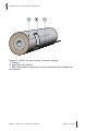
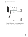
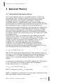
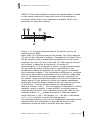
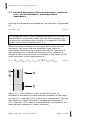
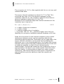
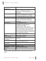
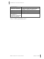
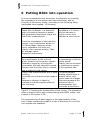
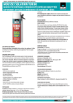
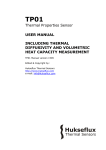
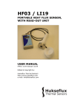
BS01
Belt Heat Flux Sensor
USER MANUAL
BS01 manual version 0607
Edited & Copyright by:
Hukseflux Thermal Sensors
http://www.hukseflux.com
e-mail: [email protected]
Hukseflux Thermal Sensors
Warning and safety issues
Exerting force on the BS01 wiring can lead to permanent
damage to the sensor. While watertight and pressure resistant,
BS01 wiring to sensor connection is not particularly strong. The
user is encouraged to avoid any unnecessary strain.
Application of more than 12 Volt across the BS01 wiring can lead
to permanent damage to the sensor.
BS01 manual version 0607
page 2/26
Hukseflux Thermal Sensors
Contents
1
1.1
1.2
2
3
4
5
6
7
8
9
10
11
11.1
11.2
11.3
11.4
List of symbols
4
Introduction
5
General Theory
8
General heat flux sensor theory
8
Detailed description of the measurement: resistance error,
contact resistance, and temperature dependence
10
Application in simulated service testing
12
Specifications of BS01
13
Short user guide
16
Putting BS01 into operation
17
Installation of BS01
18
Maintenance of BS01
19
Requirements for data acquisition / amplification 20
Electrical connection of BS01
21
Data analysis and quality assurance
22
Appendices
23
Appendix on cable extension for BS01
23
Appendix on trouble shooting
24
Appendix on heat flux sensor calibration
25
CE declaration of conformity
26
BS01 manual version 0607
page 3/26
Hukseflux Thermal Sensors
List of symbols
Heat flux
Thermal conductivity
Voltage output
Calibration factor
Time
Surface area
Electrical resistance
Thermal resistance
Temperature
Temperature dependence
Sensitivity
ϕ
λ
V
Csen
t
A
Re
Rth
T
TD
Esen
W.m-2
W/m.K
V
W.m-2/µV
s
m2
Ω
Km2/W
°C
%/K
µV/W.m-2
Subscripts
Property of the sensor
Property of tube
Property during calibration
Property of the object on which BS01 is
mounted
BS01 manual version 0607
sen
tube
cal
obj
page 4/26
Hukseflux Thermal Sensors
Introduction
The BS01 is a large area flexible heat flux and temperature
sensor for in-situ evaluation of the insulation value of pipes.
With years of experience put into the design, it is the “standard”
for pipe insulation testing for subsea oil pipes.
The BS01 contains three sensitive areas and four integrated
temperature sensors. Originally designed for “simulated service
conditions testing” for subsea oil pipelines, it can withstand high
hydrostatic pressures up to 110 bar and is (contrary to other
sensors) completely water-tight. The main development effort
has gone into the prevention of penetration of moisture into the
sensor at high pressures. With sensors not specifically prepared
for the high pressure, penetrated moisture will on the long term
lead to instability of the sensor calibration.
The sensor is provided with a mounting set for easy fixation,
consisting of a cover and two springs.
BS01 was originally designed by TNO TPD. Scientific publication
about this sensor: D. Haldane (Heriot Watt University), F. van
der Graaf, A.M. Lankhorst (TNO TPD): A direct Measurement
System to obtain the Thermal Conductivity of Pipeline Insulation
Coating Systems under Simulated Service Conditions, Offshore
Technology Conference, 1999.
In this publication the specific design considerations for heat flux
sensors in simulated service tests are outlined.
Hukseflux is specialised in themal analysis for pipeline insulation.
In addition to the BS01 also matched thermocouples for
differential temperature measurements, and specialised thermal
conductivity measurement equipment for small plastic samples
can be delivered.
BS01 manual version 0607
page 5/26
Hukseflux Thermal Sensors
Figure 0.1 BS01 on pipe during in service testing.
3 Cabling
4 Pipeline to be tested
5 BS01 mounted on pipeline (cover and springs for fixation are
not shown)
BS01 manual version 0607
page 6/26
Hukseflux Thermal Sensors
193.5
25
13
T3
100
T2
40
T1
T4
195
1.2
7
1.
2.
3.
4.
5.
6.
7.
8.
9.
10.
11.
12.
13.
14.
380
Figure 0.2 BS01 dimensions. Cable can be extended. 1 to 3
individual heat flux sensors, T1 to T4 temperature sensors (4
pieces), 4 Cabling, 1. to 6. heat flux sensor wiring, 7 to 14
temperature sensor wiring. See table 11.1.
BS01 manual version 0607
page 7/26
Hukseflux Thermal Sensors
1 General Theory
1.1
General heat flux sensor theory
As in most heat flux sensors, the actual sensors in BS01 are
thermopiles. BS01 contains 3 heat flux sensors for improved
quality assurance. A thermopile measures the differential
temperature across the plastic body of BS01. Working
completely passive, it generates a small output voltage that is
proportional to the differential temperature that powers the heat
flux travelling through it. (heat flux is proportional to the
differential temperature divided by the local thermal conductivity
of the heat flux sensor). Assuming that the heat flux is steady,
that the thermal conductivity of the body is constant and that
the sensor has negligible influence on the thermal flow pattern,
the signals of BS01 are proportional to the local heat flux in Watt
per square meter.
Using HFP01 is easy. For readout one only needs an accurate
voltmeter that works in the millivolt range. To convert the
measured voltage Vsen in microvolt to a heat flux ϕ in W/m2, the
voltage must be multiplied by the calibration factor Csen, a
constant that is supplied with each individual sensor.
In addition, for accurate measurements, a temperature
correction must be applied. The applicable temperature is
obtained by taking the average temperature as read out by the
thermocouples that are incorporated in the BS01.
ϕ = Csen (1+TD(T-Tcal)) Vsen
1.1.1
With TD the temperature dependence of the calibration factor in
%/K and Tcal the reference temperature and the temperature T in
K or degrees C. Csen is the calibration factor for the individual
sensor, so Csen should be changed depending on the exact
sensor.
In the present configuration of the BS01 design, the TD typically
is 0,17%/K and Tcal is mostly chosen to be 20 degrees C.
In this case formula 1.1.1 becomes
ϕ = Csen (1+0.0017(T-20)) Vsen
1.1.2
With T in degrees C and Vsen in microvolts.
NOTE 1: application of formula 1.1.2 only after verification of the
individual sensor calibration certificate.
BS01 manual version 0607
page 8/26
Hukseflux Thermal Sensors
NOTE 2: With most Hukseflux sensors the mathematics is based
on the sensor sensitivity (reciprocal value of the calibration
constant) rather than on the calibration constant. BS01 is an
exception for historical reasons.
Figure 1.1.1 General characteristics of a heat flux sensor as
incorporated in BS01.
When heat (6) is flowing through the sensor, the filling material
(3) will act as a thermal resistance. Consequently the heat flow ϕ
will go together with a temperature gradient across the sensor,
creating a hot side (5) and a cold side (4). The majority of heat
flux sensors is based on a thermopile; a number of
thermocouples (1,2) connected in series. A single thermocouple
will generate an output voltage that is proportional to the
temperature difference between the joints (copper-constantan
and constantan-copper). This temperature difference is, provided
that errors are avoided, proportional to the heat flux, depending
only on the thickness and the average thermal conductivity of
the sensor. Using more thermocouples in series will enhance the
output signal. In the picture the joints of a copper-constantan
thermopile are alternatively placed on the hot- and the cold side
of the sensor. The two different alloys are represented in
different colours 1 and 2. The thermopile is embedded in a filling
material, usually a plastic, in case of BS01 a special pressure
resistant polyurethane. Each individual sensor will have its own
calibration factor, Csen, usually expressed in Watt per square
meter heat flux ϕ per 1 Volt output, Vsen. The flux is calculated
ϕ= Vsen Csen, typically corrected for temperature.
The calibration factor as well as the temperature dependence are
determined at the manufacturer, and can be found on the
calibration certificate that is supplied with each sensor.
BS01 manual version 0607
page 9/26
Hukseflux Thermal Sensors
1.2
Detailed description of the measurement: resistance
error, contact resistance, and temperature
dependence
Ignoring the temperature dependence, the heat flux is expressed
as:
ϕ = Vsen Csen
1.2.1
This paragraph offers a more detailed description of the heat flux
measurement. It should be noted that the following theory for
correcting for resistance errors usually is not applied. For BS01,
usually one will work with formula 1.1.2.
When mounting the sensor on an object with limited thermal
resistance, the sensor thermal resistance itself might be
significantly influencing the undisturbed heat flux. One part of
the resulting error is called the resistance error, reflecting a
change of the local total thermal resistance of the object. A first
order correction of the measurement is:
ϕ = (Rthobj+Rthsen ) V
sen
C
sen
(1+TD(T-Tcal)) / Rthobj
1.2.2
Figure 1.2.1 The resistance error: a heat flux sensor (2)
increases or decreases the total thermal resistance of the object
on which it is mounted (1) or in which it is incorporated. This can
lead either to a larger of smaller (increase of or decrease of
the- ) heat flux (3).In case of mounting BS01 on a pipeline, the
local thermal resistance is always increased.
BS01 manual version 0607
page 10/26
Hukseflux Thermal Sensors
The correction of 1.2.2 is often applied with thin or not very well
isolated tube walls.
The sensor thermal resistance is about 6.10-3 K.m2/W. This
should be less than 1% of the thermal resistance of the
insulation material. So, the insulation material should have a
thermal resistance higher than 0.6 K.m2/W.
Because of the cilyndrical shape the thermal resistance of the
insulation layer is given by:
R = (r2/ λ ) ln (r2 / r1 )
1.2.3
r2 = radius of pipe plus insulation
r1 = radius of pipe
λ = thermal conductivity of insulation
r1 is typically 160 mm. So r2 should be higher than 240 mm,
resulting in a minimum insulation material thickness of 80 mm.
Apart from the sensor's own thermal resistance, also contact
resistances between sensor and surrounding material are
demanding special attention. Essentially any air gaps add to the
sensor thermal resistance, at the same time increasing the
deflection error in an unpredictable way. In all cases the contact
between sensor and surrounding material should be as well and
as stable as possible, so that it is not influencing the
measurement. It should be noted that the conductivity of air is
approximately 0.02 W/m.K, ten times smaller than that of the
heat flux sensor. It follows that air gaps form major contact
resistances, and that avoiding the occurrence of significant air
gaps should be a priority whenever heat flux sensors are
installed.
BS01 manual version 0607
page 11/26
Hukseflux Thermal Sensors
2 Application in simulated service
testing
BS01 has been designed for simulated service testing of oil
pipelines.
The conditions of this kind of testing are rather specific. In
particular the sensor must be water tight up to high pressures,
have a thermal resistance as well as sufficient sensitivity.
All these were taken into consideration during BS01 design.
In addition there is a need for quality assurance, which is
covered by incorporating 3 separate heat flux sensors as well as
4 separate temperature sensors.
Internal pipe diameter
Steel wall thickness
Coating thickness
Internal temperature
External temperature
Heat flux
Coating thermal conductivity
250 mm
30 mm
100 mm
110 degrees C
10 degrees C
100 W/m2
0.16 W/mK
Table 2.1 Typical condutions for simulated service testing of oil
pipelines.
BS01 manual version 0607
page 12/26
Hukseflux Thermal Sensors
3
Specifications of BS01
BS01 is a large area flexible heat flux and temperature sensor. It
measures with 3 separate sensors the local heat flux
perpendicular to the sensor surface on the object on which it is
mounted, as well as its surface temperature with 4
thermocouples. It can only be used in combination with a
suitable measurement system. BS01 is supplied with a cover and
spring for installation on a typical insulated tube.
GENERAL SPECIFICATIONS
Specified
Heat flux in W/m2 perpendicular to the
measurements
sensor surface.
Surface temperature in K
Heat flux measurement 3 separate heat flux sensors
Temperature
4 type K thermocouples
measurement
Installation
See the product manual for
recommendations.
Temperature range
0 to +100 degrees C
CE requirements
BS01 complies with CE directives
Protection Class
IP65
Pressure range
0-110 bar
the sensor has successfully been used
up to 200 bar, but this application is not
covered by factory warranty.
Cover dimensions
140 x 360 mm
Spring dimensions
length 390 mm
MEASUREMENT SPECIFICATIONS
Expected accuracy (to
Within 2.5%
50 degrees C)
Temperature
0.17%/ °C (exact value on calibration
dependence of the
certificate)
calibration coefficient
(TD)
SENSOR SPECIFICATIONS
Calibration constant
0.02 W m-2 /µV (exact value for each
Csen (nominal)
single sensor on calibration certificate)
Tcal =20 °C
Sensitivity Esen
50 µV /W m-2
(nominal)
(this parameter is normally not used
with BS01 calculations)
Thermal conductivity
0.20 W/mK +/- 10%
Table 3.1 BS01 specifications part 1 (continued on the 2 next
pages)
BS01 manual version 0607
page 13/26
Hukseflux Thermal Sensors
Sensor thermal
resistance Rth
Sensitivity to pressure
Non linearity
Range
Sensitivity to bending
Non stability
Required readout
Expected voltage
output
Power required
Internal electrical
resistance (single heat
flux sensor)
Required programming
Sensitive part
dimensions
Connector block height
Cable length, diameter
Flexibility
Weight including 3 m
cable
6 10
-3
Km2/W
Sensor construction has been optimised
to show no significant pressure
dependence. This has been empirically
confirmed.
Sensor construction has been optimised
to show no significant non-linearity.
This has been empirically confirmed.
to + 2000 Wm-2
Sensor construction has been optimised
to show no significant sensitivity to
bending. This has been empirically
confirmed.
< 1% change per year
For heat flux measurement.
3 differential voltage channel
or possibly (less ideal)
3 single ended voltage channel.
When having a lack of input channels, it
can be considered to put several heat
flux sensors in series, while working
with the average sensitivity and several
thermocouples in parallel, working as if
it is a single thermocouple.
Application in typical simulated service
test: -10 to - + 20 mV
Zero (passive sensor)
2 kOhm (nominal) including cable
resistance
For each sensor individual sensor:
ϕ = Csen (1-TD(T-Tcal)) Vsen
195 x 100 (x 1.2 mm)
7 mm
3 meters, 5 mm
30 mm minimum radius
2 kg, including metal shield on cable
Table 3.1 BS01 specifications part 2 (continued on the next
page)
BS01 manual version 0607
page 14/26
Hukseflux Thermal Sensors
CALIBRATION
Calibration traceability
to electrical power and surface area
DIN52612, ISO8302, ASTM C177
Every 2 years
Recalibration interval
Options
Extended cable
Consult manufacturer
Matched thermocouples Consult manufacturer
for readout of
temperature differential
across the insulation
Table 3.1 BS01 specifications part 3.
BS01 manual version 0607
page 15/26
Hukseflux Thermal Sensors
4 Short user guide
Preferably one should read the introduction and first chapters to
get familiarised with the heat flux measurement and the related
error sources. In particular it is recommended to estimate the
order of magnitude of the resistance error.
The sensor should be installed following the directions of the
next paragraphs. Essentially this requires a data logger and
control system capable of readout of small voltages, and
thermocouples and capability to perform multiplications and
divisions of formula 1.1.1.
The first step that is described in paragraph 5 is an indoor test.
The purpose of this test is to see if the sensor works.
BS01 manual version 0607
page 16/26
Hukseflux Thermal Sensors
5 Putting BS01 into operation
It is recommended to test the sensor functionality by checking
the impedance of the sensors and thermocouples, and by
checking if the sensor works, according to the following table:
(estimated time needed: 15 minutes)
Warning: during this part of the test,
please put the sensor in a thermally
quiet surrounding because a sensor
that generates a significant signal will
disturb the measurement.
The typical sensor
impedance is 2 kohms.
Infinite indicates a
broken circuit; zero
indicates a short circuit.
Check the impedance of the heat flux
sensors. Use a multimeter at the 10
kilo Ohms range. Measure at the
sensor resistance first with one
polarity, than reverse polarity. Take
the average value.
Repeat for each sensor.
Check if the sensor reacts to heat flux.
Use a multimeter at the millivolt
range. Measure at the sensor output.
Generate a signal by touching the
thermopiles with the hand at one side,
possibly with the other side in contact
with a relatively cold object.
Check if the thermocouples are in good
condition.
If possible use a thermocouple readout
unit.
Generate a change in signal by
touching the thermocouple locations
with the hand.
The sensor should react
by generating a millivolt
output signal.
Polarity can be reversed
by touching the sensor
at the opposite side.
The thermocouple
reading should show a
realistic value, and
should react to changes.
Otherwise measure the
resistance of the
thermocouples, this
should be a few Ohms.
Table 6.1 Checking the functionality of the sensor. The procedure
offers a simple test to get a better feeling how BS01 works, and
a check if the sensor is OK.
The programming of data loggers is the responsibility of the
user. Please contact the supplier to see if directions for use with
your system are available.
BS01 manual version 0607
page 17/26
Hukseflux Thermal Sensors
6 Installation of BS01
BS01 is generally installed on the surface, at the location where
one wants to measure.
The more even the surface on which BS01 is placed the better.
Care should be taken to prevent the creation of air gaps
between sensor and tube. Recommended contact material for
temporary installation is thermal paste of Dow Corning. In case
of permanent installation or high pressure testing, it is
recommended to apply silicone glue in a thin layer.
In case of simulated service testing, and using the cover with
springs, one could also choose to work without any contact
material; water takes over this function once the sensor is
submerged.
It is recommended to fix the location of the sensor by using the
cover and springs that are supplied with the sensor. Use of
these is self explanatory.
Table 7.1 General recommendations for installation of BS01. In
case of exceptional applications, please contact Hukseflux.
BS01 manual version 0607
page 18/26
Hukseflux Thermal Sensors
7 Maintenance of BS01
Once installed, BS01 is essentially maintenance free. Usually
errors in functionality will appear as unreasonably large or small
measured values.
As a general rule, this means that a critical review of the
measured data is the best form of maintenance.
At regular intervals the quality of the cables can be checked.
On a 2 yearly interval the calibration can be checked in an indoor
facility.
BS01 manual version 0607
page 19/26
Hukseflux Thermal Sensors
8
Requirements for data
acquisition / amplification
Below table shows a listing of specifications of the data
acquisition and amplification system for heat flux measurement.
In most experiments there will be an additional need to perform
measurements of the temperature difference across tube
insulation. This measurement is typically performed using two
matched thermocouples. These also can be supplied by
Hukseflux. The readout required for one pair (two) of such
sensors is equal to one heat flux and one temperature channel.
For heat flux measurement.
Capability to measure
microvolt signals
For temperature
measurement.
Capability to perform
measurements of
thermocouple type K
Capability for the data logger
or the software
Typical readout for differential
temperature, performed by
tow matched thermocouples
type K (not part of BS01)
3 differential voltage channel
or possibly (less ideal)
3 single ended voltage channel.
When having a lack of input
channels, it can be considered to
put several heat flux sensors in
series, while working with the
average sensitivity
Preferably: 5 microvolt accuracy
Minimum requirement: 50
microvolt accuracy
(both across the entire expected
temperature range of the
acquisition / amplification
equipment)
4 Type K thermocouple signals.
These should be read-out with
an accuracy of about
and several thermocouples in
parallel, working as if it is a
single thermocouple.
To store data, to perform
calculations for each sensor
individual sensor:
ϕ = Csen (1-TD(T-Tcal)) Vsen
One differential voltage channel
and one thermocouple channel.
Table 10.1 Requirements for data acquisition and amplification
equipment.
BS01 manual version 0607
page 20/26
Hukseflux Thermal Sensors
9 Electrical connection of BS01
In order to operate, BS01 should be connected to a
measurement and system as described above. A typical
connection is shown in table 9.1.
BS01 is a passive sensor that does not need any power.
Cables generally act as a source of distortion, by picking up
capacitive noise. It is a general recommendation to keep the
distance between data logger or amplifier and sensor as short as
possible. For cable extension, see the appendix on this subject.
Wire
Colour
Measurement system
Sensor 1 output +
Sensor 1 output -
white
white/red
Sensor 2 output +
Sensor 2 output -
Black
Black/white
Sensor 3 output +
Sensor 3 output -
Brown
Brown/white
Voltage
Voltage
ground
Voltage
Voltage
ground
Voltage
Voltage
ground
Thermocouple +
Marking 1,2,3,4
Thermocouple –
Marking 1,2,3,4
Yellow
Thermocouple input +
Red
Thermocouple input -
input +
input - or
input +
input - or
input +
input - or
Table 9.1 The electrical connection of BS01. The heat flux sensor
outputs usually are connected to differential voltage inputs.
Thermocouple location see figure 0.2
When using more than one sensor and having a lack of input
channels, see the appendix on requirements for data acquisition.
BS01 manual version 0607
page 21/26
Hukseflux Thermal Sensors
10 Data analysis and quality
assurance
It is recommended to ensure data quality by storage of all raw
data in microvolts (both of the sensors and from the
thermocouples). Measurement quality is further enhanced by
careful review of the data. In particular the data of the different
heat flux measurement results should deviate by no more than
2%, and the temperature data should differ by no more than 0.5
degrees C.
In addition it is suggested to verify that the measured data of
heat flux as well as termperature are stable within 1% or 0.5
degrees over at least 30 minutes.
BS01 manual version 0607
page 22/26
Hukseflux Thermal Sensors
11 Appendices
11.1 Appendix on cable extension for BS01
BS01 is equipped with one tube-type, pressure resistant and
water tight cable containing all 14 leads. This cable has a
watertight connection to the sensor. It is a general
recommendation to keep the distance between data logger or
amplifier and sensor as short as possible. Cables generally act as
a source of distortion, by picking up capacitive noise. Longer
pressure / water resistant cable can be ordered during
manufacturing.
For use outside the pressure vessel, BS01 cable can be extended
by thicker, more mechanically robust cabling without any
problem to 50 meters. If done properly, the sensor signal,
although small, will not significantly degrade.
Cable for
heat flux
Core
resistance
Outer
diameter
Connection
6-wire shielded, copper core (for 3 sensor signals)
0.1 Ω/m or lower
(preferred) 5-7 mm
Soldering is preferred. Clamping or good quality
connectors can also be used. Depending on the
circumstances mechanical tension reliefs can be
designed.
Table 11.1.1 Specifications for heat flux cable extension of BS01.
Cable for
3 pair shielded, type K extension cable
heat flux
Connection Clamping is preferred. Depending on the
circumstances mechanical tension reliefs can be
designed.
Table 11.1.2 Specifications for thermocouple cable extension of
BS01.
BS01 manual version 0607
page 23/26
Hukseflux Thermal Sensors
11.2 Appendix on trouble shooting
This paragraph contains information that can be used to make a
diagnosis whenever the sensor does not function.
The heat flux
sensor or
temperature
sensor does not
give any signal
Measure the impedance across the sensor wires. This
should be around 2 kohms for the heat flux sensor,
several ohms for a thermocouple. If it is closer to
zero there is a short circuit (check the wiring). If it is
infinite, there is a broken contact (check the wiring).
This check can be done even when the sensor is in
operation.
Check if the sensor reacts to an enforced heat flux or
temperature change. In order enforce a flux, it is
suggested to mount the sensor on a piece of metal,
create a thermal connection with some thermal
paste, that is used in electronics (if not available
toothpaste will also do), and to use a lamp as a
thermal source. A 100 Watt lamp mounted at 10 cm
distance should give a definite reaction of both heat
flux and temperature
Check the data acquisition by applying a mV source
to the input in the 1 mV range.
Check if the right calibration factor is entered into
The heat flux
sensor signal is the algorithm. Please note that each sensor has its
own individual calibration factor.
unrealistically
Check if the voltage reading is multiplied by the
high or low.
calibration factor by review of the algorithm.
Check if the temperature dependence is correctly
applied.
Check if the mounting of the sensor still is in good
order.
Check the condition of the leads at the logger.
Check the cabling condition looking for cable breaks.
Check the range of the data logger; heat flux could
be out of range
Check the data acquisition by applying a mV source
to it in the 1 mV range.
Check the presence of strong sources of
The sensor
electromagnetic radiation (radar, radio etc.)
signal shows
Check the condition of the shielding.
unexpected
Check the condition of the sensor cable.
variations
Table 11.2.1 Trouble shooting for BS01.
BS01 manual version 0607
page 24/26
Hukseflux Thermal Sensors
11.3 Appendix on heat flux sensor calibration
The calibration of BS01 is performed using a guarded hot plate.
In this configuration the calibration is traceable to heater power
and surface area.
The calibration is performed at several temperatures to verify
the temperature dependence.
The calibration reference conditions for BS01 calibration at TNO /
TPD are:
Temperature: 20 °C
Heat Flux: 10 W/m2
BS01 manual version 0607
page 25/26
Hukseflux Thermal Sensors
11.4 CE declaration of conformity
According to EC guidelines 89/336/EEC, 73/23/EEC and
93/68/EEC
We:
Hukseflux Thermal Sensors
Declare that the product:
BS01
Is in conformity with the following standards:
Emissions: Radiated:
Conducted:
Immunity:
EN 55022: 1987 Class A
EN 55022: 1987 Class B
ESD IEC 801-2; 1984 8kV air discharge
RF
IEC 808-3; 1984 3 V/m, 27-500 MHz
EFT IEC 801-4; 1988 1 kV mains, 500V other
Delft,
January 2006
BS01 manual version 0607
page 26/26