1
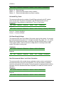
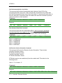
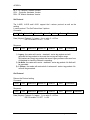
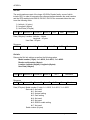
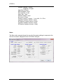
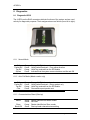
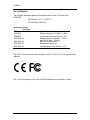
L-A210 User manual Document Reference: L-A210 V1.6 Serial Reader User Manual Date: 19th March 2012 This document is copyright and is supplied Internally in strict confidence. It must not be reproduced nor shown to third parties either in part or in its entirety without ACURA’s written consent. ABBREVIATIONS Abbreviation CR EOM I/O ID LF LSB m mm MSB NC PC Pwr RF RFID Rx SOM TBA Tx UPS RSSI PCB Meaning Carriage Return End of Message Input/Input Identity Line Feed Least Significant Bit/Byte Meter Millimetre Most Significant Bit/Byte No Connection Personal Computer Power Radio Frequency Radio Frequency Identification Receive Start of Message To be Announced Transmit Uninterruptible Power Supply Received Signal Strength Indicator Printed Circuit Board This document is copyright and is supplied Internally in strict confidence. It must not be reproduced nor shown to third parties either in part or in its entirety without ACURA’s written consent. 1 Product Compatibility ............................................................................5 2 Overview..................................................................................................6 The Reader comprises the following functionality and properties:................6 2.1 New Generation reader Properties ....................................................7 2.2 Functional Diagram ...........................................................................8 3 Hardware Configurations. ......................................................................9 4 Networking ............................................................................................ 10 4.1 Single Network structure.................................................................. 10 4.2 Basic Network Operation ................................................................. 11 4.3 Establishing Node ID Addressing (automatic assignment) .............. 12 4.4 Packet Control ................................................................................. 13 4.5 Auto Polling ..................................................................................... 15 5 Protocols and Addressing ................................................................... 17 5.1 Command Packets .......................................................................... 17 5.2 Response Packets........................................................................... 17 5.3 Addressing Techniques ................................................................... 18 6 Commands ............................................................................................ 20 6.1 Command shortlist........................................................................... 20 6.2 Command Details ............................................................................ 21 Reset Network Command .................................................................... 21 Start / Enabling Polling Mode Command............................................ 21 Disable Auto Polling Command .......................................................... 22 Ping Reader Command ........................................................................ 22 Set Network ID Command .................................................................... 23 Reader ID Command ............................................................................ 23 Get Tag Packet Command ................................................................... 23 Set RSSI Value Command.................................................................... 25 Get RSSI Value Command ................................................................... 25 Set Site Code Command ...................................................................... 25 Get Site Code Command...................................................................... 25 Set Receiver Gain Command............................................................... 26 Get Receiver Gain Command .............................................................. 26 Set Alarm Tag Filter Status Command ............................................... 26 Get Alarm Tag Filter Status Command ............................................... 26 Get Invalid Tag Count........................................................................... 27 Get Power Supply Voltage ................................................................... 27 Start Environmental Noise Level Value Calculation .......................... 27 Get Environmental Noise Level Value ................................................ 28 Reset Network Baud Rate Command.................................................. 28 Get Receiver Version Information Command..................................... 28 Set Protocol........................................................................................... 29 Get Protocol .......................................................................................... 29 Set Info .................................................................................................. 30 Get Info .................................................................................................. 30 Status..................................................................................................... 31 7 Interfaces and Connections ................................................................. 32 7.1 Interfaces......................................................................................... 32 7.2 RS232.............................................................................................. 32 7.3 Connections..................................................................................... 33 7.4 USB Connection. ............................................................................. 33 8 Diagnostics ........................................................................................... 34 8.1 Diagnostic LEDS ............................................................................. 34 8.1.1 Normal Mode ............................................................................ 34 8.1.2 Auto Poll Mode (Master reader only) ........................................ 34 8.1.3 Communications Reset (Start-up) ............................................ 34 9 Specifications ....................................................................................... 35 10 Certification ....................................................................................... 36 1 Product Compatibility The L-A210, L-A211 and IPSU are cat5 Patch lead friendly products. The Cat5 patch lead family of products are not in any way compatible with the legacy wiring loom products and can cause them damage. The L-A210 should only ever be used with the L-A211 and IPSU and must be connected using standard cat5 patch cable. Never mix or try to connect L-A210, L-A211, IPSU with legacy wiring or legacy readers. Failure to comply with this statement will damage the products and will not be covered by the terms of the warranty. If you are in any doubt please contact your local ACURA’s representative. For clarity the products are clearly identified below Legacy Wiring Family L-A202 L-A201 PSU300 Cat5 Patch Lead Friendly Family L-A210 RX210 User Manual L-A211 Page 5 of 36 IPSU ACURA’s 2 Overview The L-A210 Serial reader is the latest incarnation of the classic RS232, RS485 type network and part of the new generation of patch lead friendly products including the L-A211 and IPSU. The Reader is used in the system to perform the following functions: Receive, decode and validate data from ACURA’s L Output relevant tag data via USB or via the Reader Network. The Reader comprises the following functionality and properties: RF Module (RF Receiver and Demodulator). Micro-controller LED indicators on the output connectors. Micro USB socket 2.5mm Power plug The L-A210 Reader can be used with the following ACURA’s Antennas AN-100 / 200 / 300 / 400 and any other 433MHz antenna that has a 50 Ohm termination resistance. RX210 User Manual Page 6 of 35 ACURA’s 2.1 New Generation reader Properties The L-A202/L-A210 and L-A211 family are significantly different from there predecessor the L-A201. These differences are summarized here and explained in more detail throughout the manual. Front End Filtering The L-A202 / L-A210 / L-A211 utilize front end RF filtering allowing them to work extremely effectively in noisy RF environments including in direct proximity to other 433MHZ emitters including TETRA band. RSSI Response The L-A202 / L-A210 / L-A211 have a linear calibrated response, which includes operation at both High and Low gain modes. The sensitivity of the new readers is vastly superior to the L-A201 and allows both greater read range at large distances and also RSSI granularity allowing readers to use for reading tags as close up as 10cm. This close reading ability has obsoleted the requirement for PROX readers in the new product range; instead the user may simply apply a suitable RSSI filter. Buffer Size The L-A202 / L-A210 and L-A211 have a larger buffer size of 9 tags compared to the L-A201, which was 5 Tags. RJ45 Connection In the event that a user connected up an L-A201 incorrectly there was a high chance that the damage could be caused to the reader. All of the RJ45 connections on the L-A202/L-A210 and L-A211 are protected by self resetting fuses. In the event that the user makes a mistake and miss connects the reader, these fuses will set and the reader will appear to be dead. Check the connection then allow the reader 2 seconds to reset. USB Connection All the new generation of readers support configuration over USB. Before you get excited and plug it in please install the FTDI drivers first as detailed later in the manual. This connection can be used for standalone applications. No Nulls One of the criticisms of the L-A201 network configuration was that in auto poll the system always reported NULL TAG packets when a reader that had an empty tag buffer was polled. There is now an option to turn this off in the Protocol setting. Please note this option is only available for autopoll, a manually polled reader will always respond back with a full or empty tag packet as its ACK. TTL TTL is not supported by the L-A202 / L-A210 / L-A211 Readers RX210 User Manual Page 7 of 35 ACURA’s 2.2 Functional Diagram The L-A210 Reader has the following functional structure. RF Receiver Memory Microprocessor Controller Indication RS232 Port Left RS485 Right RS485 USB Port This receiver consists of a microprocessor controller with onboard firmware that communicates directly with the RF Receiver module and connects to the outside world via 3 serial interfaces or the USB port. Data can be sent independently to and from the 2 RS485 ports and will be simultaneously represented on the RS232 port. All connections are done via 2 RJ45 connectors and are protected against EMI and ESD noise. Connection to the USB port is made via a standard USB mini type B plug. It should be noted that the operation of the RS232 port is controlled by software and the default setting for all L-A210s is for the RS232 Port to be switched ON. When L-A210s are being deployed in a network where RS232 is being used to connect to the first reader, the RS232 should be turned off on all other readers. If the Network is being driven from an IPSU the first reader should be connected over RS485 and the RS232 should be turned off on all readers. Failure to turn the RS232 can cause additional noise in the network which over long cable runs , 100m plus will reduce the efficiency of the network causing the readers to loose tag packets. The method for turning the RS232 port on and off is detailed later in this manual. RX210 User Manual Page 8 of 35 ACURA’s 3 Hardware Configurations. ACURA’s recommend the following configuration methods Single reader for Demo Purposes The L-A210 when used as a standalone unit can draw power over the USB USB lead L-A210 Reader Network USB Host to RS485 The IPSU supports USB, RS232 and RS485 allowing it power up to 8 readers over RS485* Dependent on cable lengths. In order to power longer cable runs with more readers an IPSU can be added in line to provide extra power or individual readers can be powered through their 2.5mm Jack plugs. USB lead Cat 5 Patch IPSU RS485 L-A210 L-A210 Reader Network USB Host to RS485 with L-A211 An L-A211 can be deployed on its own or on the end of a network of L-A210’s USB lead Cat 5 Patch IPSU RX210 User Manual RS485 L-A210 Page 9 of 35 L-A211 ACURA’s 4 Networking 4.1 Single Network structure The L-A210 readers are connected together in a daisy chain type format. That is, Reader 1 is connected to Reader 2 is connected to Reader 3 etc. The network can handle a maximum of 254 readers because of addressing constraints. Communications between readers is done via a 2 wire RS485 connection. Connections from reader 1 to the PC can be done via the RS232 or Left RS485 ports. Please note that for USB connection over the network an IPSU should be used, the USB connector in the L-A210 is for diagnostic and demo purposes, when connected over the USB the RJ45 sockets are isolated. Therefore you cannot drive the network over the USB interface of the first reader. This network need not necessarily connect to a PC, but can be some other device such as a buffer or handheld computer etc. 1 RS232 or 2 wire RS485 PC 2 3 4 n 2 wire RS485 2 wire RS485 2 wire RS485 2 wire RS485 Power Data Flow Power is also carried to each reader on the cable running between them. Since each RS485 connection between readers is theoretically a separate network, distances between them can be up to 1.2 km (0.74 miles) according to the RS485 standard depending on the quality of the cable used. In reality copper wiring is not a perfect conductor and over long cable lengths significant voltage drop can occur. The L-A210 readers can be powered independently through the regulated 6-28V 2.5 mm jack connector, it is recommended for cable runs over 100m to use this option. This network operates at speeds of up to 115200 baud and down as low as 9600 baud. These baud rates can be altered, using the application software, by means of the predefined commands referred to in section 4 of this document. Data communication to and from the PC must be at the same baud rate. The reader net may be supplied with power from multiple points within the network. It is recommended that the network is powered via the ACURA’s IPSU. RX210 User Manual Page 10 of 35 ACURA’s 4.2 Basic Network Operation Data passed up and down this network is arranged in a packet format. (Explained later). Each reader can be individually addressed via 2 address techniques, or the entire network can be broadcast to by assigning the destination address as value 255. These addressing techniques will also be explained later. Data transmitted from the right port of a reader would be received in the left port of the receiver to the right of it and vice versa. With this kind of configuration, it is possible for the reader to control the direction that the data is flowing, and handle it accordingly. The complete network would look as follows: 1 2 3 4 n RS232 or 2 wire RS485 PC L R L R 2 wire RS485 2 wire RS485 R L 2 wire RS485 L R 2 wire RS485 L R Data Flow This network works on a Command/Response type operation. That is, a command is sent down to a specific reader in a left to right direction, while the response is sent back from right to left. Simply, commands run left to right, while responses run from right to left. 1 2 3 4 n RS232 or 2 wire RS485 PC L R 2 wire RS485 L R 2 wire RS485 L R 2 wire RS485 L R 2 wire RS485 Command Data Response Data RX210 User Manual Page 11 of 35 L R ACURA’s Each Command and Response is formatted into a specific packet of data with error checking etc included in the protocol format. Data can only flow in one direction at a time since the hardware is using a single serial port to control all this serial data. In order to make the installation of this system easier, it was necessary to stop the need of having to give each reader and individual address via a dipswitch or other plug in computer methods. Because this system is able to determine data direction, it is possible to establish which reader is number 1 and from there the consecutive addresses can be established. As mentioned earlier, there are 2 distinct methods of addressing a reader when sending out a command. The first address is called the NODE ID. This is the electrical address of the reader and is defined automatically by its position in the network. The first reader (very left) would be assigned NODE ID 1 and increment consecutively to the right until a maximum of 254. The second address is called the READER ID. This address is defined by the user and is written to the non-volatile memory of each reader and can be from 1 to 254. If a reader is removed from the network, or simply bypassed, the NODE ID's will naturally change. The function of the READER ID is therefore to allow a consistent and permanent address assignment to each reader. Logically, one would use NODE ID addresses in a command packet to assign a READER ID to a specific reader. NODE ID's provide a failsafe method of always accessing the correct reader if the network structure is known. 4.3 Establishing Node ID Addressing (automatic assignment) At power up, the NODE ID's are automatically established from the readers' connection position on the network. Basically, how this works is that Reader 1 needs to be established. From there, each subsequent reader can be assigned its NODE ID. This whole process takes about 3.5 seconds at power up and consists of the following sequences. 1. Each reader powers up and sets its data flow in a right hand direction. 2. Each reader then continuously sends ' * ' s out of their right hand RS485 ports, and prepares to receive this character in their left hand RS485 ports. This character is sent out in single bursts every 25ms. This avoids any framing errors should a reader not be able to lock onto the data stream in the correct position from start up. 3. If an ' * ' is received in the left RS485 port, the TAG LED (slave indicator) is illuminated to indicate this. Each reader, except Reader 1, will therefore receive this character on its left hand RS485 port. 4. Reader 1 has now been established. 5. This process of sending out the right hand RS485 port lasts for 1 second. 1 2 3 4 n RS232 or 2 wire RS485 PC L R 2 wire RS485 L R 2 wire RS485 L R 2 wire RS485 L R 2 wire RS485 L R * RX210 User Manual * * * Page 12 of 35 * ACURA’s 6. Once Reader 1 has been established, it will start continuously sending its NODE ID out of the right hand RS485 port. This will be a continuous ' 1 ' and lasts for 500ms. 7. Each remaining reader, on receiving a byte, assumes it to be the NODE ID of the reader to the left of it, adds 1 to this value and assigns it as its own NODE ID. This new NODE ID is passed again to the right. This continuous sending of NODE ID's to the right has a ripple down effect on the network, until every receiver has been assigned its NODE ID and the network has stabilised. 1 2 3 4 n RS232 or 2 wire RS485 PC L R L 2 wire RS485 R 2 wire RS485 L R 2 wire RS485 L R L R 2 wire RS485 1 2 3 4 5 8. Although the Reader 1 only sends the NODE ID 1 out for 500ms, the rest of the network remains in this receive - add 1 - transmit mode for a full second. This prevents any erroneous data from Reader 1 corrupting the whole network assignment. 9. There is now a further 1 second delay before the whole network is now ready and active. Reader 1 actually waits a further 2 seconds after its 500ms timeout before it becomes active, making it active 500ms after the others. 4.4 Packet Control As explained earlier, data is passed up and down this network in a specific packet format. It would be too slow for a reader to receive a complete packet before transmitting it on to the next reader. Because of this, the packet is transmitted byte for byte as it is received. The reader at the opposite end of the network would therefore have its packet delayed by the time taken to transmit a single byte down the length of the network. This is a relation of the baud rate and the number of readers on the network. After start up, the readers are all set into the idle condition, waiting for either a command or response packet. Here they will wait until they receive a command from the PC or a response packet from another reader. The IDLE/OK status LED will be on at this stage. Command packets (Left to Right) are transmitted across the entire length of the network. RX210 User Manual Page 13 of 35 ACURA’s 1 2 3 4 n RS232 2 wire RS485 PC L R L R 2 wire RS485 2 wire RS485 L R 2 wire RS485 L R 2 wire RS485 L R "ABCD A B C D E A B C A B A D E C D B C A B E D E C D E In the idle mode, data can be received from either direction. Since there is only one serial port on the microprocessor, the header byte received will determine from which direction the packet is being received. Once this byte has been received, the communication drivers are immediately set-up to flow the data in the correct direction. They will stay in this direction until the entire packet has been received, or the communications has timed out, whereby the reader will go back into the idle mode. While this data is being transmitted down the network, each reader assembles the packet in its memory for analysis when completed. Once a complete command packet is received, the contents are analysed for errors and addressing. Should this be a Command packet, the addressed reader(s) will then respond. After receiving a complete packet, each reader will immediately switch back into the idle mode. (Receive from both directions). In this mode, the next packet (should there be any) will automatically be passed in the correct direction. Should there be a break of more than 25ms between any bytes of the data packet, each reader will automatically switch back into the idle mode and ignore that packet. In this way, any communications failure will not result in the network locking up. Should a spontaneous response packet be initiated e.g. Network Reset as a result of a power glitch, the packet will be passed back to the PC 1 2 4 n TTL RS232 2 wire RS485 PC L RX210 User Manual L R 2wire RS485 R L 2 wire RS485 R L 2 wire RS485 R 2 wire RS485 Page 14 of 35 L R ACURA’s Each time a valid packet is received, the Packet RX LED will flash. This can be used to determine whether valid communications is taking place. Response packets are now sent back exactly the same way as the command packet, but in the opposite direction. Each reader would assemble the packet as it passed through to determine when the response is complete. Once it has received a complete response, the reader will switch into the idle mode, ready for the next Command packet. 1 2 3 4 n RS232 2 wire RS485 PC L R 2 wire RS485 L R 2 wire RS485 L R 2 wire RS485 L R 2 wire RS485 L R 4.5 Auto Polling The onboard firmware carries routines to allow this system to be auto-polled and free running. When reader 1 has the auto polling enabled, it will automatically determine the number of readers connected to its network and sequentially send commands out to receive the tag data from each reader using the 'Get Tag Packet Command 0x06'. These tag packets pass through reader 1 and onto the PC. In this mode, the PC will receive a continuous stream of tag packets without the need for its own polling system. This can be used on systems that have no ability to send data out to the network, or need only monitor the tag data as it appears, making it a very simple system without complicated polling routines. Where no tag data is available, an empty reply packet will be sent back. This enables the monitoring software to determine if there are any readers on the network that are not responding, and suggest the appropriate action. Since this data is being received on a continuous basis, a mechanism has been put into place to enable the PC to stop this process so that commands can be sent out to the network. This can be achieved by sending a break character ( in this case , ' * ' ) to reader 1. Should Reader 1 receive this character, it will stop sending 'Get Tag Packet' commands until such time that it is instructed to go back into Auto Polling mode, OR the system is switched off and powered up again. Since the network cannot see the PC while it is passing a packet from right to left ( ie to the PC ), it will be necessary to time this character to when the data packets are flowing left to right. This can be tricky, so the suggested method is to simply send a large number of ' * ' characters ( 400 - 500 ) to the network. In this manner, the network will always see these characters. To guarantee a break occurring, send 400 x ASCII 255 + ' * ' characters. The ASCII 255 character will ensure that there is no possibility of a framing error occurring and the break character not being seen. 0xF * 400 X Breaking the polling sequence does not alter the Auto Polling Flag in the Data EEPROM, but only suspends polling. After a physical reset, this system will start polling again unless the auto polling is disabled with the appropriate command. RX210 User Manual Page 15 of 35 ACURA’s Auto Polling sequences start with a complete system communications reset to ensure that the network is seen correctly. This happens each time the auto polling is switched on even at power up. RX210 User Manual Page 16 of 35 ACURA’s 5 Protocols and Addressing As mentioned earlier data flowing on this network have a specific packet format. This format is defined as follows: 5.1 Command Packets 0xA Data Network All bytes are HEX Values Receiver Node Command Data Checksum 1. 2. 3. 4. 5. 6. 7. 8. Header Length Network ID Receiver ID Node ID Command Data Checksum 1 Byte [0xAA] 1 Byte (Number of Bytes in data section) 1 Byte 1 Byte 1 Byte 1 Byte Up to 64 Bytes of Data 1 Byte CHECKSUM = [Length] XOR [Receiver ID] XOR [Token ID] XOR [Command ID] XOR [Data]…XOR [Data] 5.2 Response Packets 0x5 Data Network All bytes are HEX values. Receiver Node Command Data Checksum 9. 10. 11. 12. 13. 14. 15. 16. Header Length Network ID Receiver ID Node ID Command Data Checksum 1 Byte [0x55] 1 Byte (Number of Bytes in data section) 1 Byte 1 Byte 1 Byte 1 Byte Up to 64 Bytes of Data 1 Byte (XOR from Length to Last Data Byte), CHECKSUM = [Length] XOR [Receiver ID] XOR [Token ID] XOR [Command ID] XOR [Data]…XOR [Data] Command and Response packets are essentially identical except for the header character. This different header character enables equipment receiving all the data to differentiate between command and response packets. Since the RS232 port presents all the data at all times, it will be necessary here to be able to differentiate between these packets. RX210 User Manual Page 17 of 35 ACURA’s 5.3 Addressing Techniques The addressing system for these networks has been made as flexible as possible. This will allow for various configurations and keep the system open for later expansion etc. When addressing a reader, there are 3 addresses to take into account:1. Network ID - Identifies the network ( used in multi-network configurations ) 2. Reader ID - User defined address for a specific reader - Permanent address defined by the user 3. Node ID - Hardware address. This address is defined by the readers' position on the network All three of these bytes are settable in the header bytes of the command packet. If a zero is placed into any of these positions, it is an indication to the firmware to ignore this parameter, and only use the remaining addresses to determine the reader being addressed. If a value of 255 is placed into any of these addresses, it is an indication to the reader that this command is being broadcast to that appropriate level. A 255 value in the Network ID byte means that the command is being broadcast over all the networks. Whereas, a 255 in either the Receiver ID bytes or Node ID bytes means that the command is being broadcast to all the readers in that network. Node ID addresses take priority over Receiver ID addresses. That is, a valid Node ID address will be accepted before a valid Receiver ID. When commands are broadcast, there is no response packet generated. The only exception for this is the Reset Network Command. A simple flow diagram for this logic would be as follows: Start Ignore Command N Network ID = Network ID = 255 N N Network ID = 0 Y Y Y N N Node ID = Reader Node ID = 255 Y N Y Y Reader ID = Node ID =0 Y Accept N Reader ID = 255 Y N Reader ID = 0 N RX210 User Manual Y Page 18 of 35 ACURA’s Some examples would be as follows: 0 0 0 0 1 1 0 12 0 12 0 4 0 0 5 5 0 0 1 255 255 255 0 12 0 255 123 0 45 0 Access Reader 123 on the Network 1 Access all Readers with Reader ID = 12 on all the networks Access Reader 45 on all the Networks Access all possible readers 255 0 0 255 255 255 Access all possible readers Access all possible readers Etc … RX210 User Manual Invalid - will have no response Access Reader with Reader ID = 12 Access Reader 5 on the network Access Reader 5 on the network. Reader ID address is ignored Invalid - will have no response Access Reader with Reader ID = 4 on Network 1 Page 19 of 35 ACURA’s 6 Commands 6.1 Command shortlist Shortlist of commands and requests (Command ID’s): 0x00 0x01 0x02 0x03 0x04 0x05 0x06 0x07 0x08 0x09 0x0A 0x0B 0x0C 0x0D 0x0E 0x0F 0x10 0x11 0x12 0xFE 0xFF Reset Network Start/Enable Auto Polling Disable Auto Polling Ping Reader Set Network ID Set Reader ID Get Tag Packet Get RSSI Value Set RSSI Value Set Site Code Get Site Code Set Receiver Gain Get Receiver Gain Set Alarm Filter Get Alarm Filter Get Number of invalid Tags Get Supply Voltage Start RF white noise Get RF white noise result Set Baud Rate Get Version Information Reply Packet Continuous Reply Packet Reply Packet + Error Reply Packet Reply Packet Tag Packet Reply Packet + RSSI Reply Packet Reply Packet Reply Packet + Site Code Reply Packet Reply Packet + Gain Reply Packet Reply Packet + Status Reply Packet + Counter Reply Packet + Voltage Reply Packet Reply Packet + Result No Reply – Broadcast only Reply Packet + Version Command Shortlist RX210 User Manual Page 20 of 35 ACURA’s 6.2 Command Details Reset Network Command The function of this command is to reset the entire network, and re-establish the NODE ID addresses. The NODE ID address in the command packet should hold a 255 (broadcast value) to ensure that the entire network enters into the reset sequence. Only reader 1 will respond with the reply packet. This is the only condition under which a response is sent from a broadcast command. Note: receiving a reset network reply packet at any point where no reset command was sent, will imply that a spontaneous reset has occurred. This would probably be as the result of a power problem. Command 0xA 0x0 0x00 0x00 0xFF 0x00 Checksum Response 0x5 0x00 Network Receiver 0x01 0x00 Checksum Start / Enabling Polling Mode Command The function of this command is to set Reader 1 into an Automatic Polling sequence. It sets the Auto Polling flag in the Data EEPROM to enable Auto Polling after power up. It will establish the size of the network by sending out tag requests until such time that it gets no response. This will determine the number of readers on the network. Once this has been established, it will sequentially poll each reader indefinitely. Data responses from the readers pass through reader 1 and onto the PC. Readers without a valid tag will respond with an empty packet of data. This will enable the monitoring software to determine if any readers are no longer responding. This command can be addressed directly to reader 1, or on a broadcast basis. When broadcasting, any reader that is not Reader 1, will disable its Auto Polling flag in its Data EEPROM to avoid any problems in the future because of incorrect parameters. This command is used to restart the Auto Polling if it has been stopped by a break character. (See Auto Polling section) Command 0xA 0x00 Network Receiver Node ID 0x01 Checksum Network Receiver Node ID 0x01 Checksum Response 0x5 0x00 RX210 User Manual Page 21 of 35 ACURA’s Disable Auto Polling Command The function of this command is to disable future Auto Polling after power up by resetting the Auto Polling flag in the Data EEPROM. This command can be addressed directly to reader 1, or on a broadcast basis. Command 0xA 0x00 Network Receiver Node ID 0x02 Checksum Network Receiver Node ID 0x02 Checksum Response 0x5 0x00 Ping Reader Command The Ping Command is simply used to check if a reader is on the network and responding correctly. It can be used to read back Network ID's, Reader ID's and Node ID's. Inserted into the response from a Ping Command is and Error Number. This number refers to the last error the respective reader has experienced. Once read, this number is cleared. To clear all the errors on all the readers, simply broadcast a Ping Command. Command 0xA 0x00 Network Receiver Node ID 0x03 Network Receiver Node ID 0x03 Checksum Response 0x5 0x01 Error Checksum Error Numbers are as follows: 0 1 2 3 4 5 6 7 8 9 No errors encountered Unknown reader command received Tag Table underflow error Command Packet checksum error RF Module - Unknown command response RF Module - Unknown general response RF Module - Re-sync failure RF Module - Command response failure RF Module - Receive response failure No response packet received from polled reader RX210 User Manual Page 22 of 35 ACURA’s Set Network ID Command The function of this command is to assign the Network ID as well as commit it to the Data EEPROM. Command 0XA 0x01 Network Receiver Node ID 0x04 New Network Checksum Response 0X5 0x00 Network Receiver Node ID 0x04 Checksum Reader ID Command The function of this command is to assign the Reader ID as well as commit it to the Data EEPROM. Command 0XA 0x01 Network Receiver Node ID 0x05 New Reader ID Checksum Response 0x5 0x00 Network Receiver Node ID 0x05 Checksum Get Tag Packet Command This will be the most used command on any system. Its function to request a Tag from the reader if there is one ready for sending. A tag is removed from the tag buffer, and returned with this command, making room for a new tag. New tags from the RF Module are written over existing tags in the Tag Buffer in order to keep the data fresh. Should no tag be ready for sending, and empty packet is sent back. That is, no data in the Data field. Command 0XA 0x00 Network Receiver Node ID 0x06 Checksum Response (empty) 0x5 0x00 Network Receiver Node ID 0x06 Checksum Response ( Tag Packet ) 0x5 Data Length Network Receiver Node 0x06 Dat Checksum Next Page … RX210 User Manual Page 23 of 35 ACURA’s The Data Field would have this format: 1 2 3 4 5 6 7 8 9 10 11 12 13 14 15 16 17 18 19 20 21 22 23 24 25 26 27 28 29 30 31 32 ! * * Interval Reed Switch Counter Firmware version B C Movement switch counter Age byte MSB Age byte Age byte Age byte LSB Site code MSB Site code Site code LSB Tag ID MSB Tag ID Tag ID Tag ID LSB Type of tag flag Reader ID RSSI signal strength Checksum 20H ( reserved ) Alarm byte Node ID Network ID Reader Set RSSI Value Firmware Version LF CR RX210 User Manual Page 24 of 35 ACURA’s Set RSSI Value Command This command will set the RSSI value and commit it to the Data EEPROM. It also initiates an RF Module reset and writes the new value to the RF Module. Broadcasts here are useful to set all the readers to their most sensitive etc. The RSSI Value ranges from 0 to 255. 0 being the most sensitive. Command 0xA 0x01 Network Receiver Node ID 0x07 New RSSI Checksum Response 0x5 0x00 Network Receiver Node ID 0x07 Checksum Get RSSI Value Command This command will return the RSSI value it is currently using, and defined in the Data EEPROM. Command 0xA 0x00 Network Receiver Node ID 0x08 Checksum Response 0X5 0x01 Network Receiver Node ID 0x08 RSSI Checksum Set Site Code Command The Site Code or Site Code is a group of 3 bytes assigned to each tag. Its function is to enable the reader to filter out any tags that it receives that is not part of the site it is monitoring. These values are committed to the Data EEPROM. When a Site Code of 0 value is assigned, then all the tags read are reported. Entering a separate code, will result in any tags other than those meeting this code to be rejected by the reader. Command 0xA 0x03 Network Receiver Node 0x0 Site Site 2 Site 3 Checksum Response 0x5 0x00 Network Receiver Node ID 0x09 Checksum Get Site Code Command This command will return the active Site Codes. Command 0xA 0x00 Network Receiver Node 0x0A Checksum Response 0x5 0x0 Network RX210 User Manual Receiver Node 0x0 Site Site 2 Site 3 Page 25 of 35 Checksum ACURA’s Set Receiver Gain Command This command will set the RF Module into its 2 different gain levels. Command 0xA 0x01 Network Receiver Node 0x0B Gain Checksum Gain = 0 (Low Gain Mode – Short range reader) Gain = 1 (High Gain Mode – Long range reader) Response 0x5 0x00 Network Receiver Node ID 0x0B Checksum Get Receiver Gain Command This command will return the Receiver Gain Mode. Command 0xA 0x00 Network Receiver Node 0x0C Checksum Response 0x5 0x0 Network Receiver Node 0x0 Gain Checksum Gain = 0 (Low Gain Mode – Short range reader) Gain = 1 (High Gain Mode – Long range reader) Set Alarm Tag Filter Status Command This command will filter out tags with a specific Alarm condition. Command 0xA 0x01 Network Receiver Node 0x0D Status Checksum Status = 0 - Report all tags Status = 1 - Report only tags with an Alarm condition Status = 2 - Report only tags without any Alarm condition Response 0x5 0x00 Network Receiver Node ID 0x0D Checksum Get Alarm Tag Filter Status Command This command will return the current Alarm tag filtering status. Command 0xA 0x00 Network Receiver Node 0x0E Checksum Response RX210 User Manual Page 26 of 35 ACURA’s 0x5 0x0 Network Receiver Node 0x0 Statu Checksum Status = 0 - Report all tags Status = 1 - Report only tags with an Alarm condition Status = 2 - Report only tags without any Alarm condition Get Invalid Tag Count This command will return the number of Invalid Tags received by the RF module since the last read. This data is calculated by the RF Module and is a direct interpretation of tag collisions or read failures. This is a 2 byte value. Command 0xA 0x00 Network Receiver Node 0x0F Checksum Response 0x5 0x0 Network Receiver Node 0x0 Count_ Count_ Checksum Count_H – Counter High Byte Count_L – Counter Low Byte Get Power Supply Voltage This command will return the voltage of the power supply at this reader. It is a single byte and represents the power in 0.1 voltage increments. Eg Value 131 = 13.1 Volts Returns the voltage that the reader is receiving, via either its RJ45 ports or via the 2.5mm power socket. It will not return the voltage that it is receiving via the USB socket if this option is being used. Command 0xA 0x00 Network Receiver Node 0x10 Checksum Network Receiver Node 0x1 Voltage Response 0x5 0x0 Checksum Start Environmental Noise Level Value Calculation This command will set the reader into an evaluation mode in order to calculate the environmental white noise level at 433.92 MHz. The unit will remain in evaluation mode for a time period of 40 seconds. During this period no tag transmissions will be decoded. Once the calculation has been completed, the reader will resume normal operation. Command 0xA 0x00 Network Receiver Node 0x11 Checksum Response 0x5 0x00 Network RX210 User Manual Receiver Node 0x11 Checksum Page 27 of 35 ACURA’s Get Environmental Noise Level Value This command will retrieve the calculated value (between 0 and 255) of the environmental white noise level. Take note that this command can only follow after the Start Environmental Noise Level Value Calculation. If a command is send down to the unit, while still in evaluation mode, the reader will cancel the calculation process, reset and continue normal operation. Command 0xA 0x00 Network Receiver Node 0x12 Checksum Response 0x5 0x0 Network Receiver Node 0x1 Noise Checksum Reset Network Baud Rate Command This command will reset the network Baud Rate. It will only accept a broadcast command and there is no response sent. Changes are immediate will result in communications loss if the PC does not change its baud rate accordingly. Command 0xA 0x01 0xFF 0xFF 0xFF 0xFF Rate Checksum Rate 0 = 115200 baud Rate 1 = 57600 baud Rate 2 = 38800 baud Rate 3 = 19200 baud Rate 4 = 9600 baud Get Receiver Version Information Command This command will return the Receiver Version Information. These include Controller Firmware Version RF Module Firmware Version Controller Hardware Version RF Module Hardware Version RF Module versions are read directly from the module itself. This data is in the following format: Value = 13 = Version 1.3 Command 0xA 0x00 Network Receiver Node 0xFF Network Receiver Node 0xF Checksum Response 0x5 0x0 CFV RFV CH RH CFV - Controller Firmware Version RX210 User Manual Page 28 of 35 Checksum ACURA’s RFV - RF Module Firmware Version CHV - Controller Hardware Version RHV - RF Module Hardware Version Set Protocol The L-A202, L-A210 and L-A211 support the L series+ protocol as well as the existing L series protocol. The Set Protocol has 3 options Command 0xAA 0x02 Network ID Reader ID Node ID 0x40 Data Checksum Data (2 bytes): Protocol: 0 = legacy, 1 = no nulls, 2 = L-Plus RS 232 enable: 0 = OFF, 1 = ON Response 0x55 0x00 Network ID Reader ID Node ID 0x40 Checksum 1) Legacy, the reader will receive - standard L series tag packets and will generate Null tag packets in the event that no tags are within range. Null packets are empty tag packets that some Legacy software uses as a form of heartbeat to check the network is operating. 2) No Nulls, the reader will receive - standard L series tag packets. No Nulls will be generated 3) L Series+, the reader will receive both L series and L series+ tag packets. No nulls will be generated. Get Protocol Returns the Protocol setting Command 0xAA 0x00 Network ID Reader ID Node ID 0x41 0x02 Network ID Reader ID Node ID 0x41 Checksum Response 0x55 Protocol Data (2 bytes): Protocol: 0 = legacy, 1 = no nulls, 2 = L-Plus RS 232 enable: 0 = OFF, 1 = ON RX210 User Manual Page 29 of 35 Checksum ACURA’s Set Info The serial readers are part of the larger ACURA’s Reader family, some of which include GPS. In order to harmonize the software interface between the serial readers and the GPS enabled units RX910, RX1010, RX1310 the command allows the user to set the following fields 1) Latitude ( 4 bytes ) 2) Longitude (4bytes) 3) User Data (10 bytes) 0xAA 0x12 Network ID Reader ID Node ID 0xF0 Data Checksum Data (18 bytes): Location: Latitude – 4 bytes Longitude – 4 bytes User Data: 10 bytes Response 0x55 0x00 Network ID Reader ID Node ID 0xF0 Checksum Get Info Returns the Set Info settings as well as the following values Model number (1 byte): 1= L-A210, 2 =L-A211, 3 = L-A202 Reader serial number (4bytes) Location: Latitude (4bytes), Longitude (4bytes) User Data (10bytes) 0xAA 0x00 Network ID Reader ID Node ID Response 0x55 0x17 Network ID Reader ID Node ID 0xF1 Checksum 0xF1 Data Checksum Data (57 bytes): Model number:(1 byte): 1= L-A210, 2 =L-A211, 3 = L-A202 Status:bit 0: Not used bit 1: Not used bit 2: Autopol setting bit 3: Gain setting bit 4: Not used bit 5: Not used bit 6: RS232 enable setting bit 7: Not used Serial number (4 bytes) RX210 User Manual Page 30 of 35 ACURA’s Location: Latitude – 4 bytes Longitude – 4 bytes User Data: 10 bytes RSSI threshold: 1 byte Site code filter: 3 byte Alarm filter: 1 byte Network Voltage: 1 byte Not used: 21 bytes Protocol (1 byte):0 = legacy, 1 = no nulls, 2 = L-Plus Controller Firmware Version (1 byte) RF Module Firmware Version (1 byte) Controller Hardware Version (1 byte) RF Module Hardware Version (1 byte) Status The Status tab command shows the user all of the reader settings in response to the Get Info command, displayed below in ACURA’s Analyser. RX210 User Manual Page 31 of 35 ACURA’s 7 Interfaces and Connections 7.1 Interfaces The interface standards are as follows: Interface Serial RS232 / RS485 Baud 115 kB/s, 57.6 kB/s, 38.4 kB/s, 19.2 kB/s, 9.6 kB/s Selectable via program port Parity None Start bit 1 Stop 1 Data Bits 8 7.2 RS232 The Default setting for RS232 is ON, in the event that it has been turned off the reader must be first connected up using either 485 or the USB port. This functionality is supported by ACURA’s Analyser, first connect the L-A210 to the PC over the USB and open Analyser. Analyser will automatically connect and detect the reader type. The RS232 connectivity can be turned ON or OFF by ticking the option in the Ser Protocol tab as below. RX210 User Manual Page 32 of 35 ACURA’s 7.3 Connections The L-A210 has 2X RJ45 connectors and a 2.5mm Power socket on the back. The RJ45’s are configured as follows L-A210 Left Port 1 2 3 4 5 6 7 8 RS232 – RX RS232 – TX Vin Straight Through Straight Through Gnd RS485 + RS485 - Right Port 1 2 3 4 5 6 7 8 Gnd NC Vin Straight Through Straight Through Gnd RS485 + RS485 - Please Note that unless RS232 has been turned ON its default is OFF Standard Cat 5 cabling must be used for connecting the L-A210. 7.4 USB Connection. The USB port can be found on the top of the reader, it accepts a standard USB B micro plug. Before accessing the reader via the port the user must pre install the latest FTDI drivers for their operating system. These can be downloaded from the following URL. www.ftdichip.com. RX210 User Manual Page 33 of 35 ACURA’s 8 Diagnostics 8.1 Diagnostic LEDS The 4 LED's on the RJ45 connectors indicate functions of the system and are used entirely for diagnostic purposes. Their assignments are as follows (from left to right): 8.1.1 Normal Mode Poll Packet RX Tag RX System Orang Green Orang Green Successful Poll of current reader Valid Packet Received – From either direction Valid Tag received from the RF Module Indicates that the system communications are Idle and OK 8.1.2 Auto Poll Mode (Master reader only) Poll Packet RX Tag RX Cmd Orang Green Orang Green Successful Poll of current reader Valid Packet Received – Return packet only Valid Tag received from the RF Module Command request packet sent 8.1.3 Communications Reset (Start-up) Master Slave Break RX Orang Green Orang Green RX210 User Manual Reader identified as Master reader Not used Reader identified as Slave reader Start-up break characters transmitting Page 34 of 35 ACURA’s 9 Specifications Environmental Operating temperature Storage temperature Humidity Physical Size Weight (unit) Colour Material Connections : -40oC to +85oC o o : -20 C to +70 C : 5% to 90% (non condensing) : 105 mm x 58mm x 28mm : 118 grams : Aluminium Grey : Aluminium : 2 x RJ45 socket : 1 Mini USB type socket : 2.5mm Power socket Radio Frequency Receive Frequency Modulation Sensitivity RF Input : 433.92 MHz : ASK :-94 dB : 50 Ohm BNC Electrical Supply Voltage Max. current consumption : 7V ~ 16Vdc : 20 ma Protocol Specification Standard Data Rate Interface : 9,600 ~ 115,200 (baud rate) : RJ45 connectors RX210 User Manual Page 35 of 35 ACURA’s 10 Certification The following standards applied in accordance with Article 5 of the directive, 1999/5/EC: EN 300 220-1 V1.2.1 (1997-11) ETS 300 683 (1997-03). Summary of tests: Test Type Effective radiated power EN55022 EN55022 EN61000-4-3 EN61000-4-4 EN61000-4-2 EN61000-4-6 25 MHz-4 GHz Radiated emissions 30 MHz – 1 GHz Conducted emissions 150 kHz – 30 Radiated immunity 80 MHz – 1 GHz, excl 433.92 MHz 20 MHz Electrical fast transients Electrostatic discharge Conducted immunity 150 kHz – 80 The L-A210 has been tested and certified to meet FCC Part 15 1.01 for unintentional radiators. The L-A210 is produced in the USA to ROHS standards and contains no Lead RX210 User Manual Page 36 of 35