1
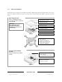
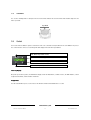
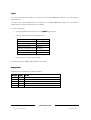
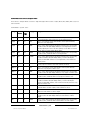
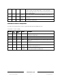
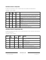
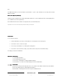
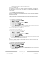
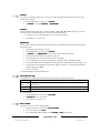
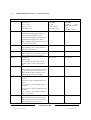
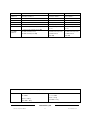
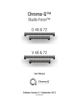
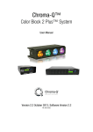
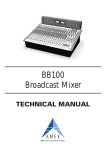
Chroma-Q®
Color Force
Compact™
User Manual
Version 1.8.1 August 2014, Software Version 1.7/1.8
PN: 627-0500
Warranty Statement
Chroma-Q warrants to the original purchaser, with proof of purchase, that its delivered products shall be free from defects in
material and workmanship under normal use for a period of 12 months from date of shipment.
Chroma-Q will repair, or at its option, provide an equivalent item or replace, the defective product during the stated warranty
period. This warranty applies only to the repair or replacement of the product and only when the product is properly handled,
installed and maintained according to Chroma-Q instructions. This warranty excludes defects resulting from improper handling,
storage, installation, acts of God, fire, vandalism or civil disturbances. Purchaser must notify Chroma-Q in writing within 14 days
of noticing the defect. This warranty excludes field labour or service charges related to the repair or replacement of the product.
The warranty contained herein shall not extend to any finished goods or spare parts from which any serial number has been
removed or which have been damaged or rendered defective (a) as a result of normal wear and tear, wilful or accidental damage,
negligence, misuse or abuse; (b) due to water or moisture, lightning, windstorm, abnormal voltage, harmonic distortion, dust, dirt,
corrosion or other external causes; (c) by operation outside the specifications contained in the user documentation; (d) by the use
of spare parts not manufactured or sold by Chroma-Q or by the connection or integration of other equipment or software not
approved by Chroma-Q unless the Customer provides acceptable proof to Chroma-Q that the defect or damage was not caused
by the above; (e) by modification, repair or service by anyone other than Chroma-Q, who has not applied for and been approved
by Chroma-Q to do such modification, repair or service unless the Customer provides acceptable proof to Chroma-Q that the
defect or damage was not caused by the above; (f) due to procedures, deviating from procedures specified by Chroma-Q or (g)
due to failure to store, install, test, commission, maintain, operate or use finished goods and spare parts in a safe and reasonable
manner and in accordance with Chroma-Q’s instructions (h) by repair or replacement of engines without factory training.
The warranty contained herein shall not apply to finished goods or spare parts which are sold “as is”, as “second-hand”, as
used”, as “demo” or under similar qualifications or to Consumables (“Consumables” is defined as any part(s) of goods or part(s)
for use with goods, which part(s) of goods or part(s) for use with goods are consumed during the operation of the goods and
which part(s) of goods or part(s) for use with goods require replacement from time to time by a user such as, but not limited to,
light bulbs).
The warranty contained herein shall not apply, unless the total purchase price for the defective finished goods or spare parts has
been paid by the due date for payment.
The warranty contained herein applies only to the original purchaser and are not assignable or transferable to any subsequent
purchaser or end-user.
This warranty is subject to the shipment of the goods, within the warranty period, to the ChromaQ warranty returns department,
by the purchaser, at the purchasers expense. If no fault is found, ChromaQ will charge the purchaser for the subsequent return of
the goods.
Chroma-Q reserves the right to change the warranty period without prior notice and without incurring obligation and expressly
disclaims all warranties not stated in this limited warranty.
www.chroma-q.com
Color Force Compact User Manual
2
V1.8.1 December 2014
Disclaimer
The information contained herein is offered in good faith and is believed to be accurate. However, because conditions and
methods of use of our products are beyond our control, this information should not be used in substitution for customer's tests to
ensure that Chroma-Q products are safe, effective, and fully satisfactory for the intended end use. Suggestions of use shall not be
taken as inducements to infringe any patent. Chroma-Q sole warranty is that the product will meet the sales specifications in
effect at the time of shipment. Your exclusive remedy for breach of such warranty is limited to refund of purchase price or
replacement of any product shown to be other than as warranted.
Chroma-Q reserves the right to change or make alteration to devices and their functionality without notice due to our ongoing
research and development.
The Chroma-Q Color Force Compact has been designed specifically for the lighting industry. Regular maintenance should be
performed to ensure that the products perform well in the entertainment environment.
If you experience any difficulties with any Chroma-Q products please contact your selling dealer. If your selling dealer is unable to
help please contact [email protected]. If the selling dealer is unable to satisfy your servicing needs, please contact the
following, for full factory service:
Outside North America:
Tel: +44 (0)1494 446000
Fax: +44 (0)1494 461024
[email protected]
North America:
Tel: 416-255-9494
Fax: 416-255-3514
[email protected]
For further information please visit the Chroma-Q website at www.chroma-q.com.
Chroma-Q and Color Force Compact are trademarks, for more information on this visit www.chroma-q.com/trademarks.
The rights and ownership of all trademarks are recognised.
Important Notice:
As per the requirements in the Occupational Safety and Health Administration standards for product approval, please refer to the
OSHA web pages http://www.osha.gov/dts/otpca/nrtl/ for information on the list of Nationally Recognized Testing Laboratories
(NRTLs) and the scope of recognition.
Table of Contents
www.chroma-q.com
Color Force Compact User Manual
3
V1.8.1 December 2014
1.
Product overview ....................................................................................................................................................... 5
2.
Operation .................................................................................................................................................................. 6
2.1
Unpacking the units .......................................................................................................................................... 6
2.2
Cabling............................................................................................................................................................. 7
2.3
Mounting .......................................................................................................................................................... 9
2.4
Optical Accessories ......................................................................................................................................... 11
2.5
Chevrons ........................................................................................................................................................ 12
2.6
Control ........................................................................................................................................................... 12
2.7
DMX Protocol.................................................................................................................................................. 26
3.
Troubleshooting ...................................................................................................................................................... 34
4.
Specification ........................................................................................................................................................... 35
5.
4.1
Technical specifications................................................................................................................................... 35
4.2
Drawings ........................................................................................................................................................ 38
4.3
Wireless Card Installation ................................................................................................................................ 41
Maintenance ........................................................................................................................................................... 43
www.chroma-q.com
Color Force Compact User Manual
4
V1.8.1 December 2014
1.
Product overview
The Chroma-Q® Color Force Compact™ is a powerful creative lighting tool that works in perfect harmony with the popular Color
Force™ range. The Compact is a cost-effective workhorse, ideal for a wide range of applications. Utilising core LED technology
from the Color Force range, the fixture provides 1700 lumens in a cost-effective, slim, compact profile.
With its rugged external design, and IP65 rated* casing the Color Force Compact has been designed as a multi-purpose
workhorse fixture suitable for numerous entertainment lighting applications - including uplighting, pipe-end shin-busting,
backlighting, wash applications and truss warmers.
The Color Force Compact uses its huge RGBA colour mixing palette to deliver a full range of high brightness colours across the
spectrum. Deep cold blues, red hot lava looks and super soft pastels are all available from a single fixture.
The Chroma-Q RGBA engine has been developed to deliver an incredible CRI of 92, for true colour balance across the spectrum.
For real versatility and compatibility with existing lighting inventories, the Color Force Compact is compatible with industry
standard top hat, half top hat, egg crate louver and barn door accessories. Other optional accessories available include clear
glass and frosted glass light lens and a W-DMX wireless option.
Complementing other models in the range, the Color Force line up now provides a full choice of creative tools for almost any
entertainment application.
Compatibility with industry standard control consoles is assured. HSI, FxHSI, RGB (*Magic Amber), RGBA, RGBI (Magic Amber),
Look Select, Master and Slave Standalone control modes are available via an external 15-way Power Supply unit, 5-way Power
Supply unit and the Color Block Power Supply units.
*As per IEC60529 ingress protection rating code.
www.chroma-q.com
Color Force Compact User Manual
5
V1.8.1 December 2014
15-way Power Supply Unit (PSU15)
The Color Force Compact PSU15 supplies power and data to a maximum total of 15 Color or Studio Force Compact fixtures. The
PSU15 features 3 XLR4 outputs and each output with a maximum capacity of up to 5 fixtures daisy-chained together. The PSU15
can be controlled remotely through an external DMX control console via XLR 5-pin cable or with the wireless option.
5-way Power Supply Unit (PSU-300)
The PSU 5 Way for Compact supplies power and data to a maximum total of 5 Color or Studio Force Compact fixtures. The PSU300 features a single XLR4 output for a maximum capacity of up to 5 fixtures daisy-chained together. The PSU-300 can be
controlled remotely through an external DMX control console via XLR 5-pin cable or with the wireless option. (Note: The PSU-300
can supply power and data to a maximum of 5 Color Block 1 or 2 fixtures.)
2.
Operation
2.1
Unpacking the units
The Color Force Compact fixture package includes the fixture, frosted or clear glass lens, accessory plate, safety cable and the
Quick Start Guide.
The PSU15 package includes the power supply unit, power cord, truss/rack mounting brackets (Rack Ears), screws and a Quick
Start Guide.
The PSU-300 package includes the power supply unit, power cord and a Quick Start Guide.
We recommend that you keep the original packaging in case the item needs to be returned.
www.chroma-q.com
Color Force Compact User Manual
6
V1.8.1 December 2014
2.2
Cabling
The Color Force Compact system use XLR 4-pin connectors for power and control data input and through. The chassis are
ground bonded.
Power Supply Output Configuration: PSU15
Maximum of 5 units per output
Output 3
Output 2
Output 1
WARNING!
PSU15
Output: Maximum of 5 fixtures per output – 48VDC, 6A per output.
Cable: The total cable length of the daisy chain per output must not exceed 60m/200ft.
Input: 100-120V~, 10A; 200-240V~, 5A; 50-60Hz
Fuse type & size: T12.5A 250V~
Power Supply Output Configuration: PSUPSU -300
Maximum length of daisy chain per output = 60m/200ft.
Maximum length of daisy chain per output = 60m/200ft.
WARNING!
PSU-300
Output: 5 fixtures – 48VDC, 6A.
Cable: The total cable length of the daisy chain must not exceed 60m/200ft.
Input: 100-120V~, 4A; 200-240V~, 2A; 50-60Hz
Fuse type & size: SLOW 5X20 4A 250V~
Color Force Compact User Manual
www.chroma-q.com
7
V1.8.1 December 2014
Power and control data outputs from the power supply to the fixture are through an XLR 4-pin cable. The drain wire should be
connected to the chassis of the XLR.
XLR 4-pin Cable:
Pin #
Function
Minimum Cable size
1
Ground (-ve)
2.50mm² (14 AWG)
2
Control data minus (-)
0.35mm² (22 AWG)
3
Control data plus (+)
0.35mm² (22AWG)
4
48V DC (+ve)
2.50mm² (14 AWG)
Chassis
Cable shield/drain wire
0.25mm² (24 AWG)
Control data signal from the external lighting control console to the power supply is through an XLR 5-pin cable.
XLR 5-pin Cable:
Pin#
Function
1
Ground (Screen)
2
Data Minus
3
Data Plus
4
Spare Data Minus
5
Spare Data Plus
Power Cable:
International Colour Code
North American Colour Code
Connections
Green and Yellow
Green
Earth (E)
Ground (Green)
Blue
White
Neutral (N)
Neutral (Silver)
Brown
Black
Live (L)
Hot (Gold)
Important Notice:
The use of an opto-splitter for DMX signal distribution is highly recommended when several fixture units are not plugged into the
same power source.
www.chroma-q.com
Color Force Compact User Manual
8
V1.8.1 December 2014
2.3
Mounting
The Color Force Compact fixture is built with a mounting yoke for floor, wall and truss mounting applications.
The yoke features an added pair of holes for height adjustment. The fixture enclosure mounted on the top holes of the yoke
allows the fixture to face upwards and perpendicular. The fixture mounted on the bottom holes of the yoke allows the fixture to
face upwards only.
Note: Secure the fixture with a safety bond. A provision for a fixing hold is built into the enclosure.
Holes for Safety bond.
www.chroma-q.com
Color Force Compact User Manual
9
V1.8.1 December 2014
The PSU15 can be rack-mounted or hung from a truss with a pair of “Rack Ears” brackets fastened with 3 x M5 FH/CS screws
onto each side or on the top of each side.
Rack-mount
Truss-mount
The PSU-300 has a unique Magic Box interlocking enclosure which facilitates easy rack mounting when used in pairs and easy
truss mounting via captive nut insert.
For truss mounting, we recommend the use of a ½”-13UNC x ¾” long bolt to avoid damage.
Rack mounting brackets are available in single unit and dual unit versions.
www.chroma-q.com
Color Force Compact User Manual
10
V1.8.1 December 2014
2.4
Optical Accessories
An optional frosted or clear glass lens is included in the package to adjust the light output of the Compact fixtures. An accessory
plate is also included to hold and lock in place accessories such as top hats, half top hats, barndoors, egg crate louvers and
others.
Glass change procedure:
Screws: 4 x M5 flathead screws
Tool: Torque screwdriver with PH #2
Torque: 15 in-lb
1. Remove the 4 screws
2. Remove the frame
Warning!
Not following the proper
procedure and torque
requirements will result in a
void warranty.
3. Change the glass
4. O-ring must be well placed
inside the channel
5. Channel
6. Put back the frame
Figure 2
C
A
7. Insert halfway the M5 screws in
this sequence:
A – B – C - D. (Fig. 3)
8. Tighten the screws to full
torque in this sequence:
A – B – C – D. (Fig. 3)
Figure 3
D
B
Accessories plate installation
procedure:
Screws: 4 x M3 flathead included in
package
1. Position the plate to match
holes. (Fig. 4)
2. Fasten the plate to the frame.
3. Use the locking plate for
adjustments and to fix in
place the accessories
Figure 4
www.chroma-q.com
Color Force Compact User Manual
11
V1.8.1 December 2014
2.5
Chevrons
The “chevron” markings that are stamped on the front of the fixture indicate the side of the fixture that should be adjacent to the
wall or cyclorama.
Cyc/Wall
2.6
Control
The PSU15 and PSU-300 can operate as stand-alone units or be controlled remotely via ANSI E1.11 USITT DMX512-A protocol.
The control functions can be accessed through the LCD display at the front with 4 push buttons.
Exit: Back to previous menu
Up Arrow: Increases (+) the mode level or value
Down Arrow: Decreases (-) the mode level or value
Back Arrow: (Enter) Stores the menu choice
PowerPower -Up Display:
On power-up and home position, the Main Menu display shows the Model Name, Software Version, the DMX Address, current
assigned Control Mode, and the number of Channels.
Display Mode:
The LCD is backlit when you access the menus. This will turn off when left undisturbed for 5 seconds.
www.chroma-q.com
Color Force Compact User Manual
12
V1.8.1 December 2014
System:
The control system of the PSU15 can be set to control Color Force Compact RGBA fixtures, Studio Force D, V and Phosphor V
Compact fixtures.
The control system of the PSU-300 can be set to control Color Force Compact RGBA fixtures, Studio Force D, V, Phosphor V
Compact fixtures, Color Block 1 and Color Block 2 Plus fixtures.
To set the control system,
1.
From the Main Menu, press Up or Down to select System,
System then press Enter
2.
Press Up or Down to select from the following options:
3.
Fixture
System Options
Color Force Compact
Color
Studio Force D Compact
Daylight
Studio Force V Compact
Varywhite
Studio Force V Phosphor Compact
Phosphor V
Color Block 1
CB1 (PSU-300 only)
Color Block 2 Plus
CB2 (PSU-300 only)
Press Enter for 2 seconds to save the settings.
The Control Mode options available will be different for each System.
Grouping options:
Grouping options are available for the control of the fixtures.
Grouping
Display
Function
Group
grp
Modes with variable grouping
Single
sng
Control of the individual LED circuits in every fixture unit
Output
out
Control of up to 5 fixtures from each PSU output as one group
All
all
Control of all fixtures from all the outputs as one group
Block
blk
Control of a single Color Block fixture as one group (PSU-300 only)
www.chroma-q.com
Color Force Compact User Manual
13
V1.8.1 December 2014
Control Modes
Modes for Color Force Compact fixture:
The Color Force Compact fixture consists of a single LED engine with 4 circuits of 7 (Red, Green, Blue, Amber) LEDs each, for a
total of 28 LEDs.
Control Modes – System - Color:
Group
Ch
PSU15
Ch
PSUPSU 300
Display
Description
Description
Single
52
22
FxHSI
gives 2 colour channels for hue, saturation and a separate intensity channel
for each single fixture and 7 channels for pre-programmed effects.
Single
45
15
HSI
gives 2 colour channels for hue and saturation, and a separate intensity
channel for each single fixture.
Single
45
15
RGB
gives 3 control channels directly affecting the intensity of the corresponding
Red, Green, Blue LED (with *Magic Amber) for each single fixture. Colour is
mixed by adjusting the levels of the three primary colours. White is achieved
with all channels at full including *Magic Amber.
Single
60
20
RGBA
gives 4 control channels directly affecting the intensity of the corresponding
Red, Green, Blue, and Amber LED for each single fixture.
Single
61
21
sRGBI
gives 3 control channels directly affecting the intensity of the corresponding
Red, Green and Blue LED (with *Magic Amber), 1 channel affecting the
intensity of all the RGB channels for each single fixture, and a channel for
intensity effects.
Output
15
FxHSI
gives 2 colour channels for hue and saturation, a separate intensity channel
for every output of 5 fixtures each, and 6 channels for effects.
Output
9
HSI
gives 2 colour channels for hue and saturation and a separate intensity
channel for every output of 5 fixtures each.
Output
9
RGB
gives 3 control channels directly affecting the intensity of the corresponding
Red, Green, Blue LED (with *Magic Amber) for every output of 5 fixtures each.
Output
12
RGBA
gives 4 control channels directly affecting the intensity of the corresponding
Red, Green, Blue, and Amber LED for every output of 5 fixtures each.
Output
13
sRGBI
gives 3 control channels directly affecting the intensity of the corresponding
Red, Green and Blue LED (with *Magic Amber), 1 channel affecting the
intensity of all the RGB channels, and 1 channel for intensity effects for every
output of 5 fixtures each.
All
9
9
FxHSI
gives 2 colour channels for hue and saturation, a separate intensity channel
for all the fixtures on all the outputs, and 6 channels for effects.
All
3
3
HSI
gives 2 colour channels for hue and saturation and a separate intensity
channel for all the fixtures on all the outputs.
All
3
3
RGB
gives 3 control channels directly affecting the intensity of the corresponding
Red, Green, Blue LED (with *Magic Amber) for all the fixtures on all the
outputs.
All
4
4
RGBA
gives 4 control channels directly affecting the intensity of the corresponding
Red, Green, Blue, and Amber LED for all the fixtures on all the outputs.
www.chroma-q.com
Color Force Compact User Manual
14
V1.8.1 December 2014
All
5
5
sRGBI
gives 3 control channels directly affecting the intensity of the corresponding
Red, Green and Blue LED (with *Magic Amber), 1 channel affecting the
intensity of all the RGB channels, and 1 channel for intensity effects for all the
fixtures on all the outputs.
1
1
Look sel
gives 1 control channel to select from the programmed scenes in the look
store.
Mastr
StandAlon
Master Standalone – assigns the unit to be the Master unit where stand-alone control
options are set.
Slave
StandAlon
Slave Standalone – assigns the unit to be the Slave unit and follows the control
options assigned to the Master unit.
Control Modes for Studio Force D Compact fixture:
The Studio Force D Compact fixture consists of a single LED engine with 28 Cold White LEDs each.
Control Modes – System – Daylight
Grouping
Ch
PSU15
Ch PSUPSU 300
Display
Description
Single
60
20
Dim4x
gives 1 channel for each LED circuit in every single fixture for a total of
4 channels per single fixture.
Single
15
5
Dim1x
gives 1 channel for all the LEDs in each single fixture.
All
1
1
Dim1x
gives 1 channel for all the LEDs in all the fixtures.
All
2
2
FxDim
gives 1 channel for intensity effects and 1 channel for all the LEDs in all
the fixtures.
1
1
Look sel
gives 1 control channel to select from the programmed scenes in the
look store.
Mastr
StandAlon
Master Standalone – assigns the unit to be the Master unit where
stand-alone control options are set.
Slave
StandAlon
Slave Standalone – assigns the unit to be the Slave unit and follows the
control options assigned to the Master unit.
www.chroma-q.com
Color Force Compact User Manual
15
V1.8.1 December 2014
Control Modes for Studio Force V Compact fixture:
The Studio Force V Compact fixture consists of a single LED engine with 14 Cold White and 14 Warm White LEDs.
Control Modes – System – Varywhite
Grouping
Ch
PSU15
Ch PSUPSU 300
Display
Description
Single
30
10
WW/CW
gives 1 channel for Warm White LEDs and 1 channel for Cold White
LEDs in every single fixture for a total of 2 channels per single fixture.
Single
30
10
CTI
gives 1 channel for Color Temperature and 1 channel for Intensity in
every single fixture for a total of 2 channels per single fixture.
All
2
2
WW/CW
gives 2 channels for Warm White and 2 channels for Cold White for all
the fixtures.
All
2
2
CTI
gives 1 channel for Color Temperature and 1 channel for Intensity for all
the fixtures.
1
1
Look sel
gives 1 control channel to select from the programmed scenes in the
look store.
Mastr
StandAlon
Master Standalone – assigns the unit to be the Master unit where standalone control options are set.
Slave
StandAlon
Slave Standalone – assigns the unit to be the Slave unit and follows the
control options assigned to the Master unit.
Control Modes for Studio Force V Compact Phosphor fixture:
The Studio Force V Compact Phosphor fixture consists of a single LED engine with 4 circuits of 7 (Red, Green, Blue, Amber) LEDs
and a remote phosphor panel.
Control Modes – System – Phosphor V
Grouping
Ch
PSU15
Ch
PSU--300
PSU
Display
Description
Single
45
15
KHL
gives 1 channel for Kelvin, 1 channel for Hue and 1 channel
for Level in every single fixture for a total of 3 channels per
single fixture.
All
3
3
KHL
gives 1 channel for Kelvin, 1 channel for Hue and 1 channel
for Level in all the fixtures.
1
1
Look sel
gives 1 control channel to select from the programmed
scenes in the look store.
Mastr
StandAlon
Master Standalone – assigns the unit to be the Master unit
where stand-alone control options are set.
Slave
StandAlon
Slave Standalone – assigns the unit to be the Slave unit and
follows the control options assigned to the Master unit.
www.chroma-q.com
Color Force Compact User Manual
16
V1.8.1 December 2014
Note:
PSU-300 Control Modes for Color Block fixtures: (Control Modes – System – CB1 and CB2) See PSU 5 Way and Color Block
Manuals for details
Other Control Options (All Models):
Internal FX engine is integrated in the software with variable parameters to create an unlimited amount of unique lighting effects.
(see 2.7 DMX Protocol for list of parameters)
Note: All internal FX are referenced back to the group base HSI colour and intensity levels.
*Magic Amber is the term used for the unit's ability to bring in amber when mixing colours that require it.
Control Menu
To set control menu options:
1.
From the Main Menu, press the Up or Down buttons to scroll through the control menu options
2.
Press Enter to select a control menu option
3.
Press the Up or Down buttons to scroll through the setting options
4.
Press Enter to select and save the setting, or press Exit to return to the previous menu without saving.
The display goes back to the Main Menu.
Main Menu / DMX Address
To set the DMX start address,
1. From the Main Menu, press Enter
2. Press the Up or Down buttons to adjust the DMX start address
3. Press Enter for 2 seconds to save and the display goes back to the Main Menu.
Control Mode
The Color Force Compact power supply unit can be set to operate in various DMX controlled modes and standalone
modes. The grouping options are Single, Output, All and Block.
In Control Mode, scroll through and select from the options available then save.
www.chroma-q.com
Color Force Compact User Manual
17
V1.8.1 December 2014
PSU15 Software V1.7, System: Color
Mode
Name
Group
Ch
Description
1
fxHSI
Group
52
7fx + 15 x HSI (Grouping, Colour Speed, Fan, Range, Step, Intensity
Fx, Intensity Fan)
2
HSI
Single
45
15 x HSI
3
RGB
Single
45
15 x RGB (with *Magic Amber)
4
RGBA
Single
60
15 x RGBA
5
sRGBI
Single
61
1s + 15 x RGBI
6
fxHSI
Output
15
6fx + 3 x HSI
7
HSI
Output
9
3 x HSI
8
RGB
Output
9
3 x RGB (*with Magic Amber)
9
RGBA
Output
12
3 x RGBA
10
sRGBI
Output
13
1s + 3 x RGBI
11
fxHSI
All
9
6fx + HSI (Colour Speed, Fan, Range, Step, Intensity Fx, Intensity Fan)
12
HSI
All
3
HSI
13
RGB
All
3
RGB (with *Magic Amber)
14
RGBA
All
4
RGBA
15
sRGBI
All
5
1s + RGBI
16
Look sel
1
Look Select
17
Mastr
StandAlon
Master Standalone
18
Slave
StandAlon
Slave Standalone
PSU15 Software V1.7, System: Daylight
Mode
Name
Group
Ch
Description
1
Dim4x
Single
60
15 x CW CW CW CW
2
Dim1x
Single
15
15 x CW
3
Dim1x
All
1
CW
4
FxDim
All
2
Int Fx + CW
16
Look sel
1
Look Select
17
Mastr StandAlon
Master Standalone
18
Slave StandAlon
Slave Standalone
www.chroma-q.com
Color Force Compact User Manual
18
V1.8.1 December 2014
PSU15 Software V1.7, System: Varywhite
Mode
Name
Group
Ch
Description
1
WW/CW
Single
30
15 x WW + 15 x CW
2
CTI
Single
30
15 x CT + 15 x Int
3
WW/CW
All
2
WW + CW
4
CTI
All
2
CT + Int
16
Look sel
1
Look Select
17
Mastr StandAlon
Master Standalone
18
Slave StandAlon
Slave Standalone
PSU15 Software V1.7, System: Phosphor V
Mode
Name
Group
Ch
Description
1
KHL
Single
45
15 x KHL
2
KHL
All
3
KHL
16
Look sel
1
Look Select
17
Mastr StandAlon
Master Standalone
18
Slave StandAlon
Slave Standalone
PSUPSU -300 Software V1.8, System: Color
Mode
Name
Group
Ch
Description
1
fxHSI
Group
22
7fx + 5 x HSI (Grouping, Colour Speed, Fan, Range, Step, Intensity Fx,
Intensity Fan)
2
HSI
Single
15
5 x HSI
3
RGB
Single
15
5 x RGB (with *Magic Amber)
4
RGBA
Single
20
5 x RGBA
5
sRGBI
Single
21
1s + 5 x RGBI
6
fxHSI
All
9
6fx + HSI
7
HSI
All
3
HSI
8
RGB
All
3
RGB (*with Magic Amber)
9
RGBA
All
4
RGBA
10
sRGBI
All
5
1s + RGBI
16
Look sel
1
Look Select
17
Mastr
StandAlon
Master Standalone
18
Slave
StandAlon
Slave Standalone
www.chroma-q.com
Color Force Compact User Manual
19
V1.8.1 December 2014
PSUPSU -300 Software V1.8, System: Daylight
Mode
Name
Group
Ch
Description
1
Dim4x
Single
20
5 x CW CW CW CW
2
Dim1x
Single
5
5 x CW
3
Dim1x
All
1
CW
4
FxDim
All
2
Int Fx + CW
16
Look sel
1
Look Select
17
Mastr StandAlon
Master Standalone
18
Slave StandAlon
Slave Standalone
PSUPSU -300 Software V1.8, System: Varywhite
Mode
Name
Group
Ch
Description
1
WW/CW
Single
10
5 x WW + 5 x CW
2
CTI
Single
10
5 x CT + 5 x Int
3
WW/CW
All
2
WW + CW
4
CTI
All
2
CT + Int
16
Look sel
17
Mastr StandAlon
Master Standalone
18
Slave StandAlon
Slave Standalone
1
Look Select
PSUPSU -300 Software V1.8, System: Phosphor V
Mode
Name
Group
Ch
Description
1
KHL
Single
15
5 x KHL
2
KHL
All
3
KHL
16
Look sel
17
Mastr StandAlon
Master Standalone
18
Slave StandAlon
Slave Standalone
1
Look Select
Note:
PSU-300 Control Modes for Color Block fixtures: (Control Modes – System – CB1 and CB2) See PSU 5 Way and
Color Block Manuals for details.
When DMX is Lost
If DMX is not detected various output options can be selected:
Off
Fixture snaps to off.
Hold
Fixture holds the last valid DMX state.
Look 1-31
Fixture snaps to the selected Look
To set an output option,
1.
From the Main Menu, scroll and select When DMX is Lost
2.
In When DMX is Lost,
Lost scroll and select an output option
3.
Press Enter for 2 seconds to save.
www.chroma-q.com
Color Force Compact User Manual
20
V1.8.1 December 2014
Look Store
In this menu, 31 internal preset Looks (effects) are available for stand-alone operation, 1-23 are pre-programmed.
To replay a Look in stand-alone operation,
1.
From the Main Menu, scroll and select Look Store
2.
In Look Store,
Store scroll and select the Look number
3.
Press Enter for 2 seconds to save.
To replay a Look with a remote DMX control console,
2.
1.
From the Main Menu, scroll and select Control Mode
In Control Mode,
Mode select Look sel
sel (Control Mode 16)
3.
Press Enter for 2 seconds to save.
Use the DMX console with the assigned channel to playback the various looks stored. (1-31 looks in 1 single
channel)
Note: DMX has priority over internal Looks.
Looks can be created, modified and recorded into Look Store by users and will be preserved on power down. Looks
will be returned to default settings if Reset is performed.
To create and save a look with a remote DMX control console:
1.
Set the fixture to the desired Control Mode.
2.
Use the DMX console to adjust channel levels and create the desired look or effect.
3.
From the Main Menu, scroll and select Look Store.
Store
4.
Scroll and select the Look Store number.
5.
Press Enter for 2 seconds to save the Look.
To create and save a look in standalone (DMX is unplugged):
1.
From the Main Menu, scroll and select Look Store
2.
Scroll and select a Look Store number
3.
Press Enter to access the memory data. The data is presented as two numbers separated by a letter “c”.
The number to the left of the “c” is the channel number and to the right is the channel level. Pressing
Up/Down up to the far end will show the Mode at which the selected Look was programmed.
To edit the Mode of a selected Look:
1.
From the Main Menu, scroll and select Look Store
2.
Scroll and select a Look Store number
3.
Press Enter to access the memory data
4.
Press the Up/Down buttons up to the far end until the Control Mode number is shown then press Enter.
5.
Press the Up/Down buttons to adjust the Mode number
6.
Press Enter to toggle back to the channel numbers
To edit the channel numbers and levels of a selected Look:
1.
From the Main Menu, scroll and select Look Store
2.
Scroll and select a Look Store number
www.chroma-q.com
Color Force Compact User Manual
21
V1.8.1 December 2014
3.
Press Enter to access the memory data
4.
Press the Up/Down buttons and select the channel number
5.
To edit the channel level, press Enter and use the Up/Down buttons to adjust the level (shown as 0-255)
6.
Press Enter to toggle back to the channel number. When the desired effect is created press Enter for 2
seconds to save the edited Look.
System
In this menu, the control system can be set to control Color Force Compact, Studio Force Compact and Color Block
fixtures:
Fixture
System Options
Color Force Compact
Color
Studio Force D Compact
Daylight
Studio Force V Compact
Varywhite
Studio Force V Phosphor Compact
Phosphor V
Color Block 1
CB1 (PSU-300 only)
Color Block 2 Plus
CB2 (PSU-300 only)
To set the control system,
1.
From the Main Menu, scroll and select System
2.
In System,
System scroll and select an option
3.
Press Enter for 2 seconds to save
Wireless
In this menu, wireless DMX connection can be activated with the power supply unit assigned as a transmitter or
receiver.
To create a new wireless network:
- set all Receivers and unlink from previous connections - Unlink frm Trnsm
- set the Transmitter and Add Receivers
To set the Wireless system of the Compact PSU,
1. From the Main Menu, scroll and select Wireless
2. In Wireless,
Wireless select from either Off,
Off Receiver or Transmitter
The display shows W reset when selecting between the options.
To activate the wireless DMX connection between generic transceiver unit as the Transmitter and the Compact PSU
unit as the Receiver:
A. Set the Compact PSU as the Receiver unit:
1.
From the main menu, scroll and select Wireless
2.
In Wireless,
Wireless select Receiver
3.
Press Enter for 2 seconds to save and display shows Wireless
4.
Press Enter, display shows Receiver
5.
Press Enter, display shows Unlink frm Trnsm
6.
Press Enter, Unlink frm Trnsm blinks for a few seconds until the display goes back to the previous menu
www.chroma-q.com
Color Force Compact User Manual
22
V1.8.1 December 2014
and then the main menu. This will unlink previous signal connections.
Proceed to set the transmitter unit.
Upon completion of a successful link with the transmitter unit, the main menu displays “w
w_” and the DMX signal
level is indicated by the horizontal bars beside it. (5 bars maximum) The menu display will indicate “wx
wx”
wx if there is
no signal connection.
B. Set the external Wireless DMX Transmitter/Transceiver:
Please refer to the User Manual of the external Transmitter/Transceiver unit for the steps to initiate signal/link with
the Compact PSU receiver unit.
To activate the wireless DMX connection between a Compact PSU unit as the Transmitter and the next Compact
PSU unit as the Receiver:
A. Set the Compact PSU unit as the Receiver unit:
1.
From the main menu, scroll and select Wireless
2.
In Wireless,
Wireless select Receiver
3.
Press Enter for 2 seconds to save and display shows Wireless
4.
Press Enter, display shows Receiver
Press Enter, display shows Unlink frm Trnsm
5.
6.
Press Enter, Unlink frm Trnsm blinks for a few seconds until the display goes back to the previous menu
and then the main menu. This will unlink previous signal connections.
Proceed to set next Compact PSU as the transmitter unit.
B. Set the Compact PSU as the Transmitter unit:
Connect DMX control to the Compact PSU unit via XLR5 cable.
1.
From the main menu, scroll and select Wireless
2.
In Wireless, select Transmitter
3.
Press Enter for 2 seconds to save and display will show Wireless
4.
Press Enter, display shows Transmitter
5.
Press Enter, display shows Add Receivers
6.
Press Enter, Add Receivers blinks for a few seconds until the display goes back to the previous menu and
then the main menu. The unit is initiating signal/link search.
Note:
The Compact PSU transmitter unit that is not connected to DMX control console continues to send wireless signal
link to the Compact PSU receiver units.
C. To unlink receivers from the Compact PSU transmitter unit:
From the main menu of the Compact PSU transmitter unit,
1.
From the main menu, scroll and select Wireless
2.
In Wireless,
Wireless select Transmitter
3.
Press Enter and then select Unlink Receivers
4.
Press Enter, Unlink Receivers blinks for a few seconds until the display goes back to the previous menu
and then the main menu.
www.chroma-q.com
Color Force Compact User Manual
23
V1.8.1 December 2014
Technical
In this mode, the frequency settings of the unit can be changed, and addressing software for the Compact LED
engines can be uploaded.
1.
From the Main Menu, scroll and select Technical
2.
In Technical,
Technical select either Frequency or Upload Heads
Heads
Frequency:
Frequency
The power supply unit has four frequency settings available - 1200, 2400, 4800, 9600. This allows for the LED
scan rate to be synchronised with the video camera and avoid a flickering effect.
1.
In Frequency, press the Up/Down buttons to select the desired frequency,
2.
Press Enter for 2 seconds to save.
Upload Heads:
Heads
The LED engine/s addressing software for the Compact fixture can be uploaded to the power supply unit from the
Chroma-Q Uploader:
1.
Connect the Compact fixture/s to the PSU.
2.
From the Main Menu, scroll and select Technical.
Technical
3.
In Technical,
Technical select Upload Heads then press Enter, and the display shows Ready
4.
Connect an XLR 5-pin cable from the Uploader to the unit.
5.
Power-up the Uploader - display shows the file name, and Ready.
6.
Press the GO button once to execute the uploading - red indicator light on the GO button blinks.
7.
The Uploader display shows a simulated arrow moving from left to right indicating the uploading process.
8.
The Green LED circuit will light up (low intensity) to indicate completion of a successful Upload and the
Uploader display shows DONE.
9.
Power-cycle the unit.
(See Quick Start Guide of the Chroma-Q Uploader)
Fan Speed (PSU15 only)
The Compact power supply units are built with internal fans with the following speed settings:
Live
fan speed is at high velocity
Live when
Light
fan speed goes to high velocity when LEDs are turned on and remain at very low velocity when
LEDs are off
Studio
fan speed is at low velocity
Quiet
fan is off
To set the Fan Speed,
1.
From the Main Menu, scroll and select Fan Speed
2.
In Fan Speed select a speed setting.
3.
Press Enter for 2 seconds to save.
Reset to Default
The fixture can be reset to factory default settings:
1.
From the main menu, scroll and select Reset to Default
2.
Press Enter, display shows reset?
3.
Press and hold Enter until the display shows resetting and done when complete
www.chroma-q.com
Color Force Compact User Manual
24
V1.8.1 December 2014
All menu items are reset to factory defaults:
PSU15
PSU-300
DMX address
001
001
Control Mode
RGBA
RGBA
When DMX is Lost
Hold
Hold
Looks
01
01
System
Color
Color
Frequency
1200
1200
Fan Speed
Live
Software Uploads:
The control software for the operation of the Compact fixtures can be uploaded directly from the Chroma-Q Uploader to the
Compact power supply unit via the XLR 5-pin connection with both units powered and no need to access the control menu.
1.
Power-up the Compact PSU.
2.
Connect an XLR 5-pin cable (single pair is fine) from the Uploader to the Compact PSU.
3.
Connect Uploader to an AC power supply. The Uploader display shows the software name and version, and ‘Ready’.
4.
Press the GO button once to execute the uploading. The Red indicator light on the GO button blinks.
5.
The Uploader display shows a simulated arrow moving from left to right indicating the uploading process.
6.
The external device resets automatically upon completion of a successful upload.
7.
The Uploader display shows ‘DONE’ upon completion of the upload.
8.
Power-cycle the Compact PSU to verify the new software version. The device display shows the new software version.
9.
Repeat step 1 to step 9 if the uploading process is interrupted (power and/or data).
www.chroma-q.com
Color Force Compact User Manual
25
V1.8.1 December 2014
2.7
DMX Protocol (PSU15 V1.7, PSU-300 V1.8)
Color Force Compact DMX Personality Mode 1-3: (Single Grouped)
Channel 1
Control Mode 1
Control Mode 2
Control Mode 3
7fx + 15 x HSI
15 x HSI
[PSU15 = 52ch]
[PSU15 = 45ch]
[PSU-300 = 22ch]
[PSU-300 = 15ch]
15 x RGB
(with
*Magic Amber) [PSU15 =
45ch]
Grouping
Hue for fixture 1
Red for fixture 1
Saturation for fixture 1
Green for fixture 1
Intensity for fixture 1
Blue for fixture 1
Hue for fixture 2
Red for fixture 2
Saturation for fixture 2
Green for fixture 2
Intensity for fixture 2
Blue for fixture 2
Hue for fixture 3
Red for fixture 3
[PSU-300 = 15ch]
0-100 Variable grouping range between 1-15
cells with FX running within the group.
102-206 variable grouping range between 1-15
cells with FX running between the groups.
209-255 Variable grouping range for every 2nd
to every 15th cell in a group.
Channel 2
Colour Speed
0-255 Variable speed of colour scrolling. From
static at 0 to maximum at 255.
Channel 3
Colour Fan
0-255 Variable fan of colour between / within
groups. All units are the same colour at 0.
Channel 4
Colour Range
0 Full spectrum
1-255 Variable limit of spectrum for colour
scrolling. Single colour at 1, full spectrum at
255.
Channel 5
Colour Step
0-255 Variable control of smoothness of colour
scrolling. Smoothest is at 0. Most coarse is at
250. Rate will vary with scrolling speed. 255
will override effects and switch to RGB.
Channel 6
Intensity Effects
0 Static
1-63 Fade on, fade off. Variable range, 63 the
fastest
64-127 Fade on, snap off. Variable range, 127
the fastest
128-191 Snap on, fade off. Variable range, 191
the fastest.
192-255 Snap on, snap off (strobe). Variable
range, 255 the fastest.
Channel 7
Intensity Fan
0-255 Variable fan of intensity effect between /
within groups. All units at the same intensity at
0. Alternating units on and off at 255.
www.chroma-q.com
Color Force Compact User Manual
26
V1.8.1 December 2014
Channel 8
Hue for fixture 1
Saturation for fixture 3
Green for fixture 3
Channel 9
Channel 10
Saturation for fixture 1
Intensity for fixture 3
Blue for fixture 3
Intensity for fixture 1
Hue for fixture 4
Red for fixture 4
Channel 11
Hue for fixture 2
Saturation for fixture 4
Green for fixture 4
Channel 12
Saturation for fixture 2
Intensity for fixture 4
Blue for fixture 4
Channel 13
Intensity for fixture 2
Hue for group fixture 5
Red for fixture 5
...and so on up to fixture 15 (PSU15)
…and so on up to fixture 5 (PSU-300)
…and so on up to fixture
15 or 5
…and so on up to fixture
15 or 5
52 DMX channels (PSU15)
45 DMX channels (PSU15)
45 DMX channels (PSU15)
22 DMX channels (PSU-300)
15 DMX channels
15 DMX channels
(PSU-300)
(PSU-300)
Total DMX
Channels
Color Force Compact DMX Personality Mode 4-5: (Single Grouped)
Control Mode 4
15 x RGBA
Control Mode 5
1s + 15 x RGBI
[PSU15 = 60ch]
[PSU15 = 61ch]
[PSU-300 = 20ch]
[PSU-300 = 21ch]
www.chroma-q.com
Color Force Compact User Manual
27
V1.8.1 December 2014
Channel 1
Red for fixture 1
Intensity Effects
0 Static
1-63 Fade on, fade off . Variable range, 63 the fastest
64-127 Fade on, snap off. Variable range, 127 the
fastest
128-191 Snap on, fade off. Variable range, 191 the
fastest.
192-255 Snap on, snap off (strobe). Variable range, 255
the fastest.
Channel 2
Green for fixture 1
Red for fixture 1
Channel 3
Blue for fixture 1
Green for fixture 1
Channel 4
Amber for fixture 1
Blue for fixture 1
Channel 5
Red for fixture 2
Intensity for fixture 1
Channel 6
Green for fixture 2
Red for fixture 2
Channel 7
Blue for fixture 2
Green for fixture 2
Channel 8
Amber for fixture 2
Blue for fixture 2
Channel 9
Red for fixture 3
Intensity for fixture 2
...and so on up to fixture 15 or 5
...and so on up to fixture 15 or 5
60 DMX channels (PSU15)
61 DMX channels (PSU15)
20 DMX channels (PSU-300)
21 DMX channels (PSU-300)
Total DMX
Channels
Color Force Compact DMX Personality Mode 6-8: (Output Grouped – PSU15 only)
Control Mode 6
6fx + 3 x HSI
Control Mode 7
HSI
[15ch]
[9ch]
3x
Control Mode 8
RGB
(with *Magic Amber) [9ch]
www.chroma-q.com
Color Force Compact User Manual
28
3x
V1.8.1 December 2014
Channel 1
Colour Speed
Hue for output 1
Red for output 1
Saturation for output 1
Green for output 1
Intensity for output 1
Blue for output 1
Hue for output 2
Red for output 2
Saturation for output 2
Green for output 2
Intensity for output 2
Blue for output 2
0-255 Variable speed of colour scrolling. From
static at 0 to maximum at 255.
Channel 2
Colour Fan
0-255 Variable fan of colour between / within
groups. All units are the same colour at 0.
Channel 3
Colour Range
0 Full spectrum
1-255 Variable limit of spectrum for colour
scrolling. Single colour at 1, full spectrum at
255.
Channel 4
Colour Step
0-255 Variable control of smoothness of colour
scrolling. Smoothest is at 0. Most coarse is at
250. Rate will vary with scrolling speed. 255
will override effects and switch to RGB.
Channel 5
Intensity Effects
0 Static
1-63 Fade on, fade off . Variable range, 63 the
fastest
64-127 Fade on, snap off. Variable range, 127
the fastest
128-191 Snap on, fade off. Variable range, 191
the fastest.
192-255 Snap on, snap off (strobe). Variable
range, 255 the fastest.
Channel 6
Intensity Fan
0-255 Variable fan of intensity effect between /
within groups. All units at the same intensity at
0. Alternating units on and off at 255.
Channel 7
Hue for output 1
Hue for output 3
Red for output 3
Channel 8
Saturation for output 1
Saturation for output 3
Green for output 3
Channel 9
Intensity for output 1
Intensity for output 3
Blue for output 3
9 DMX channels
9 DMX channels
...and so on up to output 3
Total DMX
Channels
15 DMX channels
Color Force Compact DMX Personality Mode 9-10: (Output Grouped – PSU15 only)
Control Mode 9
3 x RGBA
Control Mode 10
1s + 3 x RGBI
[12ch]
[13ch]
www.chroma-q.com
Color Force Compact User Manual
29
V1.8.1 December 2014
Channel 1
Red for output 1
Intensity Effects
0 Static
1-63 Fade on, fade off . Variable range, 63 the fastest
64-127 Fade on, snap off. Variable range, 127 the
fastest
128-191 Snap on, fade off. Variable range, 191 the
fastest.
192-255 Snap on, snap off (strobe). Variable range, 255
the fastest.
Channel 2
Green for output 1
Red for output 1
Channel 3
Blue for output 1
Green for output 1
Channel 4
Amber for output 1
Blue for output 1
Channel 5
Red for output 2
Intensity for output 1
Channel 6
Green for output 2
Red for output 2
Channel 7
Blue for output 2
Green for output 2
Channel 8
Amber for output 2
Blue for output 2
Channel 9
Red for output 3
Intensity for output 2
...and so on up to output 3
...and so on up to output 3
12 DMX channels
13 DMX channels
Total DMX
Channels
Color Force Compact DMX Personality PSU15 Mode 11-12 / PSU-300 Mode 6-7: (All Grouped)
www.chroma-q.com
Color Force Compact User Manual
30
V1.8.1 December 2014
Channel 1
Control Mode 11 (PSU15)
Control Mode 12 (PSU15)
Control Mode 6 (PSU-300)
6fx + HSI
Control Mode 7 (PSU-300)
HSI
[PSU15/PSU-300 = 9ch]
[PSU15/PSU-300 = 3ch]
Colour Speed
Hue for all fixtures
0-255 Variable speed of colour scrolling. From
static at 0 to maximum at 255.
Channel 2
Colour Fan
Saturation for all fixtures
0-255 Variable fan of colour between / within
groups. All units are the same colour at 0.
Channel 3
Colour Range
Intensity for all fixtures
0 Full spectrum
1-255 Variable limit of spectrum for colour
scrolling. Single colour at 1, full spectrum at
255.
Channel 4
Colour Step
0-255 Variable control of smoothness of colour
scrolling. Smoothest is at 0. Most coarse is at
250. Rate will vary with scrolling speed. 255
will override effects and switch to RGB.
Channel 5
Intensity Effects
0 Static
1-63 Fade on, fade off . Variable range, 63 the
fastest
64-127 Fade on, snap off. Variable range, 127
the fastest
128-191 Snap on, fade off. Variable range, 191
the fastest.
192-255 Snap on, snap off (strobe). Variable
range, 255 the fastest.
Channel 6
Intensity Fan
0-255 Variable fan of intensity effect between /
within groups. All units at the same intensity at
0. Alternating units on and off at 255.
Channel 7
Hue for all fixtures
Channel 8
Saturation for all fixtures
Channel 9
Intensity for all fixtures
Total DMX
Channels
9 DMX channels
3 DMX channels
Color Force Compact DMX Personality PSU15 Mode 13-15 / PSU-300 Mode 8-10: (All Grouped)
www.chroma-q.com
Color Force Compact User Manual
31
V1.8.1 December 2014
Control Mode 13 (PSU15)
Control Mode 14 (PSU15)
Control Mode 15 (PSU15)
Control Mode 8
(PSU-300)
Control Mode 9 (PSU-300)
RGBA
Control Mode 10 (PSU-300)
1s + RGBI
RGB
[4ch]
(with *Magic Amber)
[5ch]
(with *Magic Amber)
[3ch]
Channel 1
Red for all fixtures
Red for all fixtures
Intensity Effects
0 Static
1-63 Fade on, fade off. Variable
range, 63 the fastest
64-127 Fade on, snap off. Variable
range, 127 the fastest
128-191 Snap on, fade off. Variable
range, 191 the fastest.
192-255 Snap on, snap off (strobe).
Variable range, 255 the fastest.
Channel 2
Green for all fixtures
Green for all fixtures
Red for all fixtures
Channel 3
Blue for all fixtures
Blue for all fixtures
Green for all fixtures
Channel 4
Amber for all fixtures
Channel 5
Total DMX
Channels
Blue for all fixtures
Intensity for all fixtures
3 DMX channels
4 DMX channels
5 DMX channels
Color Force Compact DMX Personality Mode 16:
Mode 16
[1ch] Look Select
www.chroma-q.com
Color Force Compact User Manual
32
V1.8.1 December 2014
Channel 1
Channel levels and the corresponding Look numbers:
Channel Level (%)
Look
0
OFF
Description
1–2
1
Full Colour Scroll (5 sec)
3–5
2
Full Colour Scroll (10 sec)
6–9
3
Full Colour Scroll (30 sec)
10–11
4
Warm Colour Scroll (5 sec)
12–15
5
Warm Colour Scroll (10 sec)
16–19
6
Warm Colour Scroll (30 sec)
20–22
7
Cold Colour Scroll (5 sec)
23-25
8
Cold Colour Scroll (10 sec)
26–27
9
Color Colour Scroll (30 sec)
29-32
10
Red Full
33–35
11
Pink Full
36-38
12
Orange Full
39-42
13
Light Orange Full
43-45
14
Yellow Full
46-48
15
Light Yellow Full
49-51
16
Green Full
52-54
17
Light Green Full
56-58
18
Cyan Full
59-61
19
Light Cyan Full
62-64
20
Blue Full
65-68
21
Light Blue Full
69-71
22
3200 White
72-74
23
5600 White
75-78
24
Empty
79-81
25
Empty
83-85
26
Empty
86-88
27
Empty
89-91
28
Empty
92-94
29
Empty
95-97
30
Empty
98-100
31
Empty
www.chroma-q.com
Color Force Compact User Manual
33
V1.8.1 December 2014
3.
Troubleshooting
Troubleshooting is a process of elimination. First, rule out the other field factors (i.e. bad connections, faulty cables and power
supplies). For technical support and/or parts, please contact your selling dealer or the offices listed in this manual.
Symptom
Possible Cause
Solution
Fixture does not respond to DMX
control.
PSU is set to wrong or different DMX
address.
Check DMX address and Mode settings.
Bad cable connection between DMX
control and PSU.
Bad cable connection between PSU and
Compact fixtures.
Check/replace DMX run from the
console to the PSU.
Check/replace extension cables
between adjacent fixtures.
Check/replace fixtures.
Bad in/through connection between
adjacent fixtures.
Fixture malfunction.
Noise from power supply unit.
Low LED output from the fixture.
Fan malfunction.
Check fan.
Fan speed addressing.
Check fan speed mode.
Internal temperature of the PSU unit is
over the limit.
Check “Fan Speed” mode of the PSU
unit.
Fans of the PSU unit are not working.
Check the fans of the PSU unit.
Fixture malfunction.
Check PSU unit for airflow - to and from
the internal fans.
Check PSU area ventilation.
Check/replace fixture unit.
www.chroma-q.com
Color Force Compact User Manual
34
V1.8.1 December 2014
4.
Specification
4.1
Technical specifications
Color Force Compact
Product Code
CHCFCRGBA
Net Dimensions
212mm x 196mm x 152mm / 8.4” x 7.7” x 6”
(Without Fixings) - Width x Height x Depth
Net Weight (Without Fixings)
4 kgs / 8.5 lbs
Shipping Dimensions - Width x Height x Depth
267mm x 254mm x 241mm / 10.5" x 10" x 9.5"
Shipping Weight
5.4kgs / 12 lbs
Power & Connections:
Power Input Rating
48V DC
Power Consumption
60W
Power connector In/Out
XLR 4-pin
Data Connectors In/Out
XLR 4-pin
Max cable run
~60m/200ft
Power
External
Control Protocol
ANSI E1.11 USITT DMX 512-A
Cooling System
Convection
Construction
Cast Machined Enclosure
Colour
Black
Built-In Hardware
Yoke assembly
IP Rating
**IP65
Approvals
CISPR22 :2006/EN55022 :2006 & CISPR
24 :1997/EN55024 :1998, ICES-003 :2004 & FCC Part 15
Subpart B: 2007
Control & Photometric:
LEDs
28
LED Engines
1
LEDs Per Engine
28
Total LEDs
28
Control Modes
FxHSI, HSI, RGB, RGBA, sRGBI, Look Select, Master Standalone,
Slave Standalone
Dimming Curve
Theatrical
Variable Effects Engine
Yes
Effects Parameters
Grouping, colour speed, colour fan, colour range, colour step,
intensity effects and intensity fan
www.chroma-q.com
Color Force Compact User Manual
35
V1.8.1 December 2014
Hot Lumen Output (Combined)
1700
Red
350
Green
960
Blue
90
Amber
700
Optics
Specialised close focus lens
Beam Angle
14º (approx.)
Beam Angle With Optional Frosted Lens
21º (approx.)
Beam Distribution
Asymmetrical direct illumination
CCT
Adjustable 1,000 – 10,000K
Colour Gamut
Performance enhanced
CRI
92
Lamp Life
L70 at 50,000 hours
Operating Temperature
0ºC - 40ºC
**As per IEC60529 ingress protection rating code.
15-way Power Supply Unit
Product Code
CHCFCPSU15
Net Dimensions (Without Fixings) - W x H x D
429mm / 16.9” x 132mm / 5.2” x 267mm / 10.5”
Net Weight
9.5kg /21lbs
Power input rating
100-120V~, 10A; 200-240V~, 5A; 50-60Hz
Power Factor
0.9
Power Consumption
900W (Maximum); 30W (Stand-by)
Power Connectors In/Out
IEC (Power input), 3 x XLR 4-pin (Power & data output)
Data connector In/Out
XLR 5-pin male in / XLR 5-pin female thru
Max cable run
~60m / 200ft (XLR 4-pin - PSU to last unit)
Control protocol
ANSI E1.11 DMX-512A
Cooling system
Forced – 3 x fans
Operating Temperature
0ºC - 40ºC
Construction
Powder coated aluminium
Built-in Hardware
Detachable rack-mounting brackets "Rack Ears" and M4 pem
nut provision for optional bumper feet installation
Colour
Black
IP Rating
IP20
Operating temperature
0ºC to 40ºC
Approvals
CSA C22. No. 166-M1983: R2008
CAN/CSA-C22.2 No. 60950-1-07
UL 60950-1:2007, EN 60950-1/A1:2010
www.chroma-q.com
Color Force Compact User Manual
36
V1.8.1 December 2014
5-way Power Supply Unit
Product Code
CHPSU300
Net Dimensions (Without Fixings) – W x H x D
219mm / 8.6”, 88mm / 3.5”, 279mm / 11”
Net Weight
3.8kg / 8.4lb
Power Input Rating
100-120VAC, 4A; 200-240VAC, 2A; 50-60Hz
Power Factor
0.9
Power Consumption
360W (Maximum); 12W (Stand-by)
Power Connectors In/Out
IEC (Power input), XLR 4-pin (Power & data output)
Data Connectors In/Out
XLR 5-pin male in / XLR 5-pin female thru
Max cable run
~60m/200ft (XLR 4-pin - PSU to last unit)
Control Protocol
ANSI E1.11 USITT DMX 512-A
Cooling System
Forced - 1 fan
Operating Temperature
0°C - 40°C
Construction
Powder coated steel
Colour
Black
Built-In Hardware
Nut insert for ½"-13UNC x ¾" bolt
IP Rating
IP20
Approvals
CSA C22. No. 166-M1983: R2008 CAN/CSA-C22.2 No. 609501-07 UL 60950-1:2007, EN 60950-1/A1:2010
www.chroma-q.com
Color Force Compact User Manual
37
V1.8.1 December 2014
4.2
Drawings
Color Force Compact
www.chroma-q.com
Color Force Compact User Manual
38
V1.8.1 December 2014
Color Force Compact PSU15
www.chroma-q.com
Color Force Compact User Manual
39
V1.8.1 December 2014
PSU 5 Way for Compact
www.chroma-q.com
Color Force Compact User Manual
40
V1.8.1 December 2014
4.3
Wireless Card Installation
Instructions for installing W-DMX option on PSU15
When upgrading PSU15 with the W-DMX option please follow the steps below:
1.
Open the unit by removing the M3x6 screws that hold the cover. Save the screws. Put the cover aside and make sure
the ground harness is not damaged
2.
Check if the addressing card has a standoff attached, if not use the standoff and lock washer provided to create the
mounting point for the W-DMX card as shown in Figure 1
Figure 1
3.
Before mounting the card in the unit, attach the antenna cable first in the mating connector on the card
www.chroma-q.com
Color Force Compact User Manual
41
V1.8.1 December 2014
Figure 2
4.
Attach the W-DMX card using the pan head M3x6 provided; make sure that the connector on the card fits nicely on the
mating connector on the addressing PCB existing in the unit. Make sure that the antenna cable is routed opposite to
the power supplies towards the wall of the unit.
Figure 3
5.
Take the Antenna bracket subassembly and attach it to the chassis using the M3x6 flat screws provided
Figure 4
6.
Screw in the antenna then fold it in the existing space so it doesn’t get damaged. The antenna can be unfolded at any
time when it needs to be used.
www.chroma-q.com
Color Force Compact User Manual
42
V1.8.1 December 2014
Figure 5
7.
5.
Reattach the cover using the screws saved
Maintenance
With care, the Color Force Compact fixture and power supply unit will require little maintenance. However, as the unit is likely to
be used in a stage environment we recommend periodical internal inspection and cleaning of any resulting dust and cracked oil
residue.
Do not spray liquids on the front or rear panel. If the front enclosure requires cleaning, wipe with a mild detergent on a damp
cloth.
www.chroma-q.com
Color Force Compact User Manual
43
V1.8.1 December 2014