1
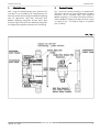
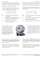
Präzision
Precision
Montage- und Wartungsanleitung
Assembly and Service Manual
Units Baureihe CSG-2UH
CSG-2UH Series Units
Harmonic Drive AG
900149
01/2006
Harmonic Drive AG
CSG-2UH Units
Contents
Inhalt
1.
2.
2.1
2.2
2.3
2.4
2.5
2.6
2.7
2.7.1
2.8
3.
3.1
3.1.1
3.1.2
3.2
3.2.1
4.
4.1
4.2
4.2.1
4.2.2
4.2.3
4.2.4
5.
5.1
5.1.1
5.1.2
5.1.3
5.1.4
5.2
5.2.1
5.2.2
5.2.3
5.2.4
6.
7.
8.
8.1
8.2
8.3
9.
10.
2
Schnittzeichnung
3
Allgemeine Hinweise
4
Vorbemerkung
4
Herstellererklärung
4
Sicherheitshinweise
4
Garantie
5
Bezeichnung des Getriebes
5
Lagerung
5
Empfohlene Toleranzen der Eingangswelle
5
Herstellung des Adapterflansches
6
Schutz gegen Korrosion und das Eindringen
von Flüssigkeiten und festen Fremdkörpern
7
Anlieferungszustand
8
Getriebe mit Fettschmierung
8
Betriebsposition mit überwiegend senkrecht
stehendem oder unten liegendem
Wave Generator
9
Betriebsposition mit überwiegend oben
liegendem Wave Generator
9
Getriebe mit Ölschmierung
10
Ölmenge
11
Vorbereitung zur Montage des Getriebes
11
Allgemeine Hinweise
11
Montage-Hilfsstoffe
11
Flächendichtung
11
Schraubensicherung
12
Montagepaste
12
Klebstoffe
12
Montage
12
Montageschritte Variante 1
12
Montage des Adapterflansches an den Motor 12
Überprüfung der Fett- bzw. Ölmenge
13
Montage des Wave Generators auf die
13
Motorwelle
Montage der Baugruppe Motor/Adapterflansch
14
an die Unit
14
Montageschritte Variante 2
14
Montage des Adapterflansches an die Unit
Überprüfung der Fett- bzw. Ölmenge
14
Montage des Wave Generators auf die
Motorwelle
14
Montage des Motors an die Baugruppe
Getriebe-Adapterflansch
14
Überprüfung der richtigen Montage
15
Verschraubung der Unit mit dem Maschinengestell und der Last
15
Wartung und Schmierung
17
Getriebe mit Fettschmierung
17
Getriebe mit Ölschmierung
19
Abtriebslager
20
Entsorgung/Gesundheitsschutz
20
Haftungsausschluss
20
1.
2.
2.1
2.2
2.3
2.4
2.5
2.6
2.7
2.7.1
2.8
3.
3.1
3.1.1
3.1.2
3.2
3.2.1
4.
4.1
4.2
4.2.1
4.2.2
4.2.3
4.2.4
5.
5.1
5.1.1
5.1.2
5.1.3
5.1.4
5.2
5.2.1
5.2.2
5.2.3
5.2.4
6.
7.
8.
8.1
8.2
8.3
9.
10.
Sectional Drawing
General Information
Preliminary notes
Declaration of conformity
Safety instructions
Warranty
Designation of the gear
Storage
Recommended input shaft tolerances
Manufacturing of the adaptor flange
Protection against corrosion and
penetration of liquids and debris
Gear Conditions at Delivery
Gears with grease lubrication
Operation mainly with Wave Generator in
vertical position or below
Operation mainly with Wave Generator above
Gears with oil lubrication
Oil quantity
Assembly Preparation
General information
Auxiliary materials for assembly
Surface sealing
Screw fixing
Assembly paste
Adhesives
Assembly
Assembly procedure variant 1
Assembly of the adaptor flange to the motor
Grease or oil quantity check
Assembly of the Wave Generator on the
motor shaft
Mounting of the motor/adaptor flange
sub-assembly to the Unit
Assembly procedure variant 2
Assembly of the adaptor flange to the Unit
Grease or oil quantity check
Assembly of the Wave Generator on the
motor shaft
Assembly of the motor to the gear-adaptor
flange sub-assembly
Assembly Control
Connecting the Unit to the Machine Housing
and the Load
Maintenance and Lubrication
Grease lubrication
Oil lubrication
Output bearing
Disposal/Health Protection
Disclaimer of Liability
3
4
4
4
4
5
5
5
5
6
7
8
8
9
9
10
11
11
11
11
11
12
12
12
12
12
12
13
13
14
14
14
14
14
14
15
15
17
17
19
20
20
20
900149 01/2006
Harmonic Drive AG
1.
Schnittzeichnung
Abb. 1 zeigt die Schnittzeichnung einer Standard CSG2UH Unit in der Ausführung für Fettschmierung. Der
Wave Generator kann mit integrierter Oldham Kupplung
oder als soge n a n n ter Solid Wave Generator, ohne
Oldham Kupplung, ausgeführt we rden. Beide Wave
Generator Typen sind jeweils als Halbschnitt dargestellt.
Der Adapterflansch gehört optional zum Lieferumfang.
CSG-2UH Units
1.
Sectional Drawing
Fig. 1 shows the sectional drawing of a standard CSG2UH Unit in the version for grease lubrication. The Wave
Generator can be designed either with integrated
Oldham Coupling or as so-called Solid Wave Generator,
without Oldham Coupling. Both Wave Generator types
are shown in Fig. 1. The adaptor flange is an optional
part of delivery.
Abb. / Fig. 1
900149 01/2006
3
Harmonic Drive AG
2.
Allgemeine Hinweise
CSG-2UH Units
2.
General Information
2.1
Preliminary notes
Dear Customer, you have acquired a very
reliable product, which has been manu factured with great care. Careful assem bly and the observation of the follo wing safety guidelines are necessary if
the products are to realize their high
technical performance.
Special versions may differ from those
described herein. If you have any
doubts whatsoever, we strongly advise
that you consult Harmonic Drive, giving
type, designation and part- or serial number.
2.1 Vorbemerkung
Sehr verehrter Kunde, Sie haben ein sehr zuverlässiges Produkt erworben, das mit großer Sorgfalt
gefertigt wurde. Zur Erzielung der vo l l e n
Leistungsfähigkeit ist eine sorgfältige Montage
und die Beachtung der nachfo l ge n d e n
Hinweise erforderlich.
Sonderausführungen können in technischen
Details von den nachfolgenden Ausführungen
abweichen. Bei eventuellen Unklarheiten wird
dringend emp fohlen, unter Angabe von
Typbezeichnung und
Teilenummer
bzw.
Seriennummer bei Harmonic Drive anzufragen.
2.2 Herstellererklärung
Harmonic Drive Getriebe sind Komponenten zum Einbau
in Maschinen im Sinne der Maschinenrichtlinie
89/392/EWG. Die Inbetriebnahme ist so lange untersagt, bis die Konformität des Endproduktes zu dieser
Richtlinie festgestellt ist.
2.2 Declaration of conformity
Harmonic Drive gears are components for installation in
machines as defined by the machine directive
89/392/EWG. Commissioning is prohibited until such
time as the end product has been proved to conform to
the provisions of this directive.
2.3
2.3
4
Sicherheitshinweise
Sämtliche Arbeiten am Getriebe sind im Stillstand
und ausschließlich von qualifiziertem Personal durchzuführen.
Das Getriebe darf nur zur bestimmungsgemäßen
Verwendung als Getriebe eingesetzt werden. Aus
sicherheitstechnischen und thermischen Gründen ist
der Betrieb nur bei vollständiger Verschraubung des
Getriebes mit dem Maschinengestell und der Last
e rlaubt. Bei nicht best i m m u n g s gemäßer Verwendung trägt allein der Benutzer das Risiko für Funktionsstörungen und Schäden. Der Hersteller wird von
der Haftung freigestellt.
Jede Änderung am Getriebe, die ohne unsere vorherige schriftliche Genehmigung vo rgenommen
wird, führt zum Verlust aller Garantieansprüche.
Der Hersteller der Maschine oder Anlage, der das
Getriebe in sein Produkt einbaut, ist verpflichtet,
durch geeignete technische Vorrichtungen zu verhindern, dass bei Funktionsstörungen des Getriebes
oder anderer Bauteile der Maschine bzw. Anlage in
der Nähe befindliche Personen in Gefahr geraten.
Die Getriebe sind in den Standardversionen für
Umgebungstemperaturen von 0 bis 40 °C ausgelegt. Während des Betriebs können an den Getrieben Oberflächentemperaturen von bis zu 80 °C auft reten. Es dürfen keine te mperaturempfindlichen
Teile, wie z.B. Elektrokabel oder elektronische Bauteile, anliegen oder befestigt werden. Ggf. sind Berührungsschutzmaßnahmen vorzusehen.
Safety instructions
Any work done on the gear must be carried out
while the gear is at a standstill.
The gear should not be put to improper use, or used
in a way not intended by its manufacturer. For reasons of safety and to avoid thermal problems the
gear should only be operated when already attached
completely to the machine housing and the load.
Should the user violate these guidelines, then he
alone, and not the manufacturer, must assume total
responsibility for any risks.
Modifications of any kind carried out on the gear
without our expressed prior written agreement nullifies all guarantee claims.
The machine or plant manufacturer who uses the
gear in his machines or plant must ensure that
should faults occur - irrespective of whether the fault
is caused by the gear or by other elements in the
machine or plant - the machine or plant will be
brought to a halt in such a way as to avoid complete or partial damage to the machine or plant, as well
as any danger to any person(s) near the machine or
plant.
The standard versions of the gears are developed for
ambient temperatures of 0 to 40 °C. During service
the gear surface temperature may reach 80 °C. No
temperature sensitive items such as wires or electronic components should be touching or attached to
the surface. If necessary, take precautions to prevent
contact.
900149 01/2006
Harmonic Drive AG
2.4 Garantie
Die Haftung des Herstellers für Mängel und daraus entstehender Folgen wird ausgeschlossen, wenn die Mängel
verursacht sind durch:
nicht bestimmungsgemäße Ve rwendung des
Getriebes
fehlerhafte Montage durch den Käufer oder Dritte
Betrieb ohne vollständige Verschraubung mit dem
Maschinengestell und der Last
fehlerhafte oder nachlässige Wartung
Verwendung nicht freigegebener Schmierstoffe
natürlichen Verschleiß
weitere Ve rwendung nach dem Auft reten vo n
Funktionsstörungen
nicht schriftlich vom Hersteller genehmigte Eingriffe
am Getriebe durch den Kunden.
CSG-2UH Units
2.4 Warranty
Liabilities resulting from the following actions will not be
covered by the manufacturer’s guarantee:
unsuitable or improper application of the gear
faulty assembly by the buyer or a third party
when the gear is operated without being attached
completely to the machine housing and the load
faulty or careless maintenance
utilisation of lubricants other than those which are
prescribed by the manufacturer
natural wear
continued use in spite of the appearance of defects
modifications of any kind carried out on the gear
without our expressed prior written agreement.
Please also refer to our delivery and payment conditions.
B i t te beach ten Sie hierzu auch unsere
Lieferungs- und Zahlungsbedingungen.
2.5 Bezeichnung des Getriebes
Bitte beach ten Sie, dass die
Bestellbezeichnung des Getriebes
auf dem Lieferschein in bestimmten Fällen aus internen Gründen
von der Bezeichnung auf dem
Getriebe abweichen kann.
2.5
Designation of the gear
Please realize that due to internal reasons
the ordering code given on the delivery
note may not always be identical with the
label on the gear itself.
2.6 Lagerung
Wird das Getriebe nach der Auslieferung nicht gleich in
Betrieb genommen, so ist es in einem trockenen Raum
und in der Originalverpackung zu lagern. Die zulässige
Lagertemperatur beträgt -20 °C bis +60 °C.
2.6 Storage
If the gear is not put into service immediately on recei pt, it should be stored in a dry area in the original pack aging. The permissible storage temperature range is
-20 °C to +60 °C.
2.7
Empfohlene Toleranzen der Eingangswelle
(Motorwelle)
Die Genauigkeit des Getriebes wird u.a. von den
Toleranzen der Getriebeeingangswelle (Motorwelle) und
des Einga n g s fl a n s ches (Ad a pterfl a n s ch zum Moto r )
beeinflusst.
2.7
Die einga n g s s e i t i gen (Moto r-) Wellen und Flansch toleranzen sollten der DIN 42955 genügen. Zur optimalen Nutzung der hervorragenden Getriebeeigenschaften
und beim Einsatz eines Solid Wave Generators (s. Abb. 7)
empfehlen wir die Toleranzklasse R.
The input (motor) shaft and flange tolerances should
fulfil the DIN 42955 standard. To utilize the excellent
properties of the gears to their fullest extent we recom mend the use of the R tolerance class. We also recom mend the R tolerance class when the gear features a
solid Wave Generator, without Oldham Coupling (see
Fig. 7).
900149 01/2006
Recommended input shaft tolerances
(motor shaft)
The accuracy of the gear is among others dependent on
the gear input shaft tolerances (motor shaft) and the
input flange (adaptor flange for the motor) at the custo mer.
5
Harmonic Drive AG
CSG-2UH Units
2.7.1 Manufacturing of the adaptor flange
For the manufacturing of the adaptor flange we recom mend the dimensions and tolerances given in Fig. 2 and
Table 1. To achieve the given value for concentricity and
run-out we recommend that the motor- and gear-side
centerings, see Fig. 2, surface B and C, are manufactu red at a single set-up.
All bore holes and thread holes must be chamfered.
2.7.1 Herstellung des Adapterflansches
Wir empfehlen bei der Produktion des Adapterflansches
die Einhaltung der Ab m e s s u n gen und Toleranzen
gemäß Abb. 2 und Tabelle 1. Zur Erzielung der angegebenen Werte für Koaxialität und Planlauf sollten die
motor- und getriebeseitigen Zentrierflächen, siehe Abb.
2, Flächen B und C, unbedingt in einer einzigen
Aufspannung gedreht werden.
Alle Bohrungen und Gewindebohrungen müssen mit
Fasen versehen sein.
Abb. / Fig. 2
[mm]
Tabelle / Table 1
CSG-2UH
Baugröße / Size
14
17
20
25
32
40
45
50
58
65
Koaxialität f a
Concentricity f a
0,03
0,04
0,04
0,04
0,04
0,05
0,05
0,05
0,05
0,05
Planlauf b
Runout b
0,03
0,04
0,04
0,04
0,04
0,05
0,05
0,05
0,05
0,05
Rundlauf c
Runout c
0,015
0,015
0,018
0,018
0,018
0,018
0,021
0,021
0,021
0,021
fP
73
79
93
107
138
160
180
190
226
260
t
3
3
4
4
4
5
5
5
6
6
fT
38H7
48H7
56H7
67H7
6
90H7 110H7 124H7 135H7 156H7 177H7
900149 01/2006
Harmonic Drive AG
2.8
Schutz gegen Korrosion und das Eindringen von
Flüssigkeiten und festen Fremdkörpern
Material: Gehäuse: Grauguß und
Wälzlagerstahl. Adapterflansch, falls von
Harmonic Drive mitgeliefert: hoch f e stes
Aluminium oder Stahl. Oberflächen:
Schrauben
schwarz
phosphatiert.
Gehäusefl ä chen: blank. Kreuzrollenlager:
blanker Wälzlagerstahl. Das umgebende
Medium sollte keine korrosive Wirkung auf
die o. g. Werkstoffe haben.
Option: Gehäuse und Abtriebslager in korrosionsgeschützter Ausführung. Bitte ggf.
Rücksprache mit Harmonic Drive.
Das Produkt erreicht die Schutzart IP65,
wenn durch die Umgebungsbedingungen
(Flüssigkeiten, Gase, Taubildung) ke i n e
Korrosion an der (den) Lauffläche(n) der
Radialwellendichtung(en) hervo rge rufen
wird, und abtriebseitig ein geschlossener
Abtriebsflansch angeschraubt ist. Die
Flanschschrauben sind mit Schraubensicherung (z. B. Loctite 243) zu dichten.
Antriebseitig ist der Adapterflansch mittels
O-Ring Dichtung, zum Motorflansch ggf.
mit Flächendichtung (z. B. Loctite 5203
oder Loxeal 28-10) zu dichten.
Scharfkantige oder abrasiv wirkende Teile
Nein/No
(Späne, Splitte r, Staub aus Metall,
Mineralien usw.) dürfen nicht mit Radialwellendichtungen in Kontakt kommen.
Ein permanent auf einer Radialwellendichtung stehender Flüssigkeitsfilm sollte verhindert werden.
Hintergrund: Bei vollständig abgedichteter
Unit entstehen info l ge wechselnder
Betriebstemperaturen Druckdifferenzen in
der Unit, die zum Einsaugen der auf einer
We l l e n d i chtung stehenden Flüssigke i t
f ü h ren können. Gegenmaßnahme: Ggf.
eine zusätzliche, kundenseitige Wellendichtung oder Sperrluftanschluss (konstanter Nein/No
Überdruck in der Unit mit get rockneter,
gefilterter Luft, max. 104 Pa). Ggf. bitte
Rücksprache mit Harmonic Drive.
900149 01/2006
CSG-2UH Units
2.8
Protection against corrosion and penetration of
liquids and debris
Material: Housing: cast iron and bearing
steel.
Adapter flange, if supplied by Harmonic
Drive: high-tensile aluminium or steel.
Screws: black phosphatized.
Housing surfaces: bright. Cross-roller bearing: Bright bearing steel. The ambient
medium should not have any corrosive
effects on the above mentioned material.
Option: Housing and output bearing are
available in corrosion-protected material.
Please contact Harmonic Drive AG for further advice.
The product provides protection class IP65
under the provision that corrosion from the
ambient atmosphere (condensation,
liquids or gases) at the running surface of
the rotary shaft seal(s) is prevented and
provided that a closed output flange is
connected at the output side. The flange
screws must be sealed f or example with
Loctite 243. At the input side the adapter
flange must be sealed by means of an oring seal. The connection of the adapter
flange to the motor flange must be sealed
for example with Loctite 5203 or Loxeal
28-10, if necessary.
Contact between sharp-edged or abrasive
objects (cutting chips, splinters, metallic or
mineral dust etc.) and the output shaft seal
must be prevented.
In addition, permanent contact between
the output shaft seal and a permanent
liquid covering should be prevented. Please
note that the changing operating temperature of a completely sealed unit can lead to
a pressure differential between the environment and the inside of the unit. This can
cause liquid covering the output shaft seal
to be drawn into the actuators housing,
which can lead to corrosive damage.
As a countermeasure we recommend the
use of an additional shaft seal (to be provided by the user) or the maintenance of a
constant pressure inside the actuator by
applying dry filtered air at a overpressure of
not more than 104 Pa. Please contact
Harmonic Drive AG for further advice.
7
Harmonic Drive AG
3.
Anlieferungszustand
Die Getriebe werden grundsätzlich gemäß den Angaben
auf der Bestä t i g u n g s z e i chnung ausge l i e f e rt. Die
Lieferung erfolgt inklusive der für die Montage erforderlichen O-Ringe und Schrauben, wenn diese in den
Katalog- oder Bestätigungszeichnungen ange ge b e n
sind.
Die für die Genauigkeit entscheidenden Getriebeteile
Flexspline, Wave Generator und Circular Spline werden
im Werk zueinander gepaart, entsprechend beschriftet,
je nach Produkt befettet oder mit Konservierungsöl benetzt, und dann gemeinsam in eine Unit eingebaut. Bei
Anlieferung mehrerer Units muss darauf geachtet werden, dass die Wave Generatoren nicht vertauscht werden. Bitte stellen Sie daher sicher, dass die von Ihnen
zusammengefügten Getriebekomponenten jeweils mit
gleichen Endziffern beschriftet sind.
3.1 Getriebe mit Fettschmierung
Die Units werden standardmäßig mit einer Fettfüllung
ge l i e f e rt. Abb. 3 zeigt die bei Anlieferung vo n
Standardgetrieben fertig geschmierten Bereiche. Wenn
nichts anderes vereinbart wurde, sind die Units der
Baugrößen 14 und 17 mit dem Fett SK-2 und Units der
Baugröße 20 - 65 mit dem Fett SK-1A gefettet. Beim
Einsatz eines anderen Fettes ist der Fett-Typ auf der
Ku n d e n z e i chnung ve r m e rkt. Das Hoch l e i st u n g s f ett
4BNo.2 ist für diese Produkte einsetzbar.
CSG-2UH Units
3.
Gear Conditions at Delivery
The gears are generally delivered according to the
dimensions indicated in the confirmation drawing.
Accessory parts like O-rings or screws will be delivered
by Harmonic Drive AG if they are mentioned in the cata logue or confirmation drawings.
The three basic components of the unit - the Flexspline,
Wave Generator and Circular Spline - are matched and
labelled in the factory. Depending on the product they
are either greased or prepared with preservation oil.
Then the individual components are assembled. If you
receive several units, please be careful not to mix up the
Wave Generators. This can be avoided by verifying that
the final numbers of the assembled gear components
are identical.
3.1 Gears with grease lubrication
Units are supplied with standard grease lubricant. Fig. 3
shows the areas where lubrication is required and which
are filled with grease lubrication at the time of delivery.
If no special arrangements are made the specially developed high perfomance grease SK-1A (for sizes 20 to 65)
and SK-2 (for size 14 and 17) are used. If any other grease is used this will be indicated on the customer drawing. High performance 4BNo. 2 grease with improved
characteristics is also available for these products.
Abb. / Fig. 3
Fettbefüllung für
Wave Generator
The following components
are supplied with grease
lubricant ex factory:
Circular Spline
Wave Generator
Flexspline
Circular Spline
und Abtriebslager
Flexspline
and output bearing
erfolgt werkseitig.
Die im folgenden Text definierten Betriebspositionen
„Wave Generator oben“ bzw. „Wave Generator unten“
beziehen sich auf die relative Lage des Wave Generators
zum Abtriebslager der Unit, s. Abb. 4.
8
The following operating positions „Wave Generator
above“ or „Wave Generator below“ refer to the position
of the Wave Generator in relative to the output bearing
of the Unit, see Fig. 4.
900149 01/2006
Harmonic Drive AG
CSG-2UH Units
Abb. / Fig. 4
Betriebspositionen / Operating Positions
Wave Generator oben / above
Wave Generator senkrecht/ vertical
Wave Generator unten/ below
3.1.1 Betriebsposition mit überwiegend senkrecht stehendem oder unten liegendem
Wave Generator
Die im Anlieferungszustand enthaltene Fettmenge ist
für den Betrieb mit überwiegend senkrecht stehendem
oder unten liegendem Wave Generator ausgelegt.
3.1.1 Operation mainly with Wave Generator
in vertical position or below
The supplied grease quantity is calculated for a Unit
operating mainly with Wave Generator in vertical positi on or below.
3.1.2 Betriebsposition mit überwiegend oben
liegendem Wave Generator
Bei überwiegendem Einsatz mit oben liegendem Wave
Generator ist eine zusätzliche Fettmenge oberhalb des
Wave Generators zu platzieren, siehe Abb. 5 und Tabelle
2. Das zusätzlich erforderliche Fett sollte vom gleichen
Typ wie das bereits in der Unit befindliche Fett sein.
Falls vereinbart, wird es jeweils zusammen mit dem
Getriebe geliefert. Ansonsten muss es separat bestellt
werden, s. Tab. 3.
3.1.2 Operation mainly with Wave Generator
above
If the gear is mainly operated with Wave Generator
above additional grease must be supplied above the
Wave Generator, see Fig. 5 and Table 2. The additional
grease should be of the same type as the grease which
is already used. If there is a special arrangement the
grease can be delivered together with the gear.
Otherwise it must be ordered separately, see Table 3.
Abb. / Fig. 5
Bei überwiegendem Einsatz
mit oben liegendem Wave
Generator ist diese zusätzliche Fettbefüllung erforderlich.
In diesem Fall muss ca.
60% des ve rfügbaren
Volumens im Ad a pterflansch mit Fett befüllt werden.
900149 01/2006
If the units are used mainly
with Wave Generator
above, then additional
grease lubrication is neces sary.
In this case about 60% of
the available space in the
adaptor flange must be fil led with grease.
9
Harmonic Drive AG
CSG-2UH Units
Tabelle / Table 2
Fettschmierung / Grease lubrication
CSG-2UH
Baugröße/Size
Standard Fettmenge
Zusätzlich erforderliche Fettmenge bei
überwiegendem Einsatz mit oben
liegendem Wave Generator
Standard Fett
Standard grease
quantity
Additionally required grease quantity
for operation with
Wave Generator above
Standard grease
ca. [g]
ca. [cm3]
ca. [g]
ca. [cm3]
14
5,5
6
3
3
17
10
11
4
5
20
16
18
9
9
25
40
44
13
14
32
60
66
22
24
40
130
143
44
49
45
180
198
59
65
50
260
286
72
79
58
360
396
117
129
65
440
484
141
155
Harmonic Drive
SK-2
Harmonic Drive
SK-1A
Tabelle / Table 3
Bestellbezeichnung für Schmierfett
Verfügbare Gebinde
Available packages
Ordering code for grease
[kg]
Spezialfett / Special grease SK-1A, SK-2
0,5; 2,5; 16
Spezialfett / Special grease 4BNo.2
0,5; 2; 16
3.2 Getriebe mit Ölschmierung
Harmonic Drive Units mit Ölschmierung sind im allgemeinen kundenspezifische Sonderanfertigungen. Bitte
befolgen Sie die Hinweise auf der Bestätigungszeichnung. Von Harmonic Drive freigegebene Schmieröle finden Sie in Tabelle 6. Die Öltemperatur sollte während
des Betriebes 90°C nicht überschreiten. Die Units werden standardmäßig ohne Ölfüllung geliefert. Das Öl
muss vom Kunden eingefüllt werden.
10
3.2 Gears with oil lubrication
Harmonic Drive Units with oil lubrication are generally
customer-specific solutions. Please follow the notes
given on the confirmation drawing and refer to Table 6
for allowed oil types. The oil temperature during opera tion must not exceed 90°C. Oil must be filled into the
unit by the customer as the standard delivery does not
include any oil lubricant.
900149 01/2006
Harmonic Drive AG
CSG-2UH Units
3.2.1 Ölmenge
Ausschlaggebend für die einzufüllende Ölmenge ist die
Angabe auf der Bestätigungszeichnung. Die auf der
Bestätigungszeichnung definierte Ölmenge ist genau
einzuhalten. Eine zu große Ölmenge führt zu übermäßiger Erwärmung und frühzeitigem Verschleiß durch thermische Zerstörung des Öls. Eine zu geringe Ölmenge
führt
zu
frühzeitigem
Ve rschleiß
infolge
Mangelschmierung.
3.2.1 Oil quantity
The values specified in the confirmation drawing inclu de the valid oil quantities to fill in. The oil quantity defi ned on the confirmation drawing must be obeyed in any
case. Too much oil results in excessive heat production
and early wear due to the thermal destruction of the oil.
If the oil level is too low, this may lead to early wear as
a result of lubricant deficiency.
4.
4.
Vorbereitung zur Montage des Getriebes
Assembly Preparation
Die Getriebemontage muss mit großer Sorgfalt und in
sauberer Umgebung erfolgen. Es ist darauf zu achten,
dass während der Montage keinerlei Fremdkörper in das
Getriebe gelangen.
The gear assembly must be carried out very carefully
and within a clean environment. Please make sure that
during the assembly procedure no foreign particles
enter the gear.
4.1 Allgemeine Hinweise
Um einen ausre i chenden Reibungskoeffi z i e n ten zwischen den Oberflächen herzustellen, müssen die zu verschraubenden Flächen vor der Montage gereinigt, entfettet und getrocknet werden. Alle für die Übertragung
des Abtriebsmomentes der Unit eingesetzten Schrauben
(siehe Tabelle 5 und Abb. 10) müssen der
Festigkeitsklasse 12.9 genügen und mit einem Drehmomentschlüssel ange z o gen werden. Sicherungselemente wie Unterlegscheiben oder Zahnscheiben dürfen nicht eingesetzt werden.
4.1 General information
Clean, degrease and dry all mating surfaces to ensure
an adequate coefficient of friction. The values given in
Table 5 and in Fig. 10 are valid for 12.9 quality screws
which must be tightened by means of a torque wrench.
Locking devices such as spring washers or toothed was hers should not be used.
4.2 Montage-Hilfsstoffe
Wir empfehlen den Einsatz folgender MontageHilfsstoffe oder gleichwertiger Produkte. Bitte beachten
Sie die Anwendungshinweise des Herstellers. MontageHilfsstoffe dürfen nicht in das Getriebe gelangen.
4.2 Auxiliary materials for assembly
For the assembly, we recommend the application of the
following auxiliary materials or the use of those with
similar characteristics. Please pay attention to the appli cation guidelines given by the manufacturer. Auxiliary
materials must not enter the gear.
4.2.1 Flächendichtung
4.2.1 Surface sealing
Loctite 5203
Loxeal 28-10
Empfohlen für alle Flanschflächen, falls keine O-RingDichtung vorgesehen ist.
900149 01/2006
Loctite 5203
Loxeal 28-10
Recommended for all mating surfaces, if the use of Oring seals is not intended.
11
Harmonic Drive AG
CSG-2UH Units
4.2.2 Schraubensicherung
4.2.2 Screw fixing
Loctite 243
Loctite 243
Schwer lösbar und dich tend. Emp fohlen für alle
Schraubenverbindungen.
This adhesive ensures that the screw is fixed and also
provides a good sealing effect. Loctite 243 is recom mended for all screw connections.
4.2.3 Montagepaste
4.2.3 Assembly paste
Klüber Q NB 50
Klüber Q NB 50
Empfohlen für O-Ringe, die während der Montage aus
ihrer Nut herausspringen können. Alle anderen O-Ringe
sollten vor der Montage leicht mit dem im Getriebe
befindlichen Fett eingestrichen werden.
Recommended for O-rings which may come out of the
groove during the assembly procedure. Before starting
with the assembly you should spread some grease
(which you can take from the gear) on all other O-rings.
4.2.4 Klebstoffe
4.2.4 Adhesives
Loctite 638
Loctite 638
Einsetzbar für geklebte, schwer lösbare Wellen-NabenVe r b i n d u n gen zwischen Motorwelle und Wave
Generator (Hub). Bitte nur benutzen, wenn dies in der
Bestätigungszeichnung vorgesehen ist.
Apply Loctite 638 to the connections between motor
shaft and Wave Generator (hub). You should make use
of it only if this is specified in the confirmation drawing.
5.
5.
Montage
Vom Getriebehersteller angezogene Schrauben dürfen
nicht gelöst werden.
Bei der Montage der Units werden, abhängig von den
Abmessungen der Ko mponenten, unterschiedliche
Vorgehensweisen empfohlen, siehe Tabelle 4, Abb. 6
und 8.
Assembly
Screws which have been tightened by the gear manu facturer must not be loosened.
Depending on the dimensions of the components, there
are different methods of assembly possible, as indicated
in Table 4 and shown in Fig. 6 and 8.
Tabelle / Table 4
[mm]
Baugröße / Size
14
17
20
Motor-Zentrier ø e
<36
<43
<50
<62,5 <81,5
<100
Motor centering ø e
≥36
≥43
≥50
≥62,5 ≥81,5 ≥100
5.1
25
32
Montageschritte Variante 1
(gemäß Abbildung 6)
5.1.1 Montage des Adapterflansches an den Motor
Adapte rflansch (1) mittels Schrauben (4) mit dem Motor (2)
verschrauben. Dichtung zum Moto rflansch (Kap. 4.2.1)
beachten, falls erforderlich.
12
40
65
Montage
gem. Abb.
Assembly acc.
to Fig.
<114 <124,5 <146
<164
6
≥114 ≥124,5 ≥146
≥164
8
45
5.1
50
58
Assembly procedure variant 1
(according to Fig. 6)
5.1.1 Assembly of the adaptor flange to the motor
Connect the adaptor flange (1) to the motor (2) by
means of the screws (4). Apply sealing to the motor flan ge (chapter 4.2.1), if necessary.
900149 01/2006
Harmonic Drive AG
CSG-2UH Units
Abb. / Fig. 6
5.1.2 Überprüfung der Fett- bzw. Ölmenge
Bitte beachten Sie hierzu die Angaben in Kapitel 3.
5.1.2 Grease or oil quantity check
Please refer to chapter 3 for more information.
5.1.3 Montage des Wave Generators auf die
Motorwelle
5.1.3 Assembly of the Wave Generator on the
motor shaft
Den gefetteten Wave Generator (5) bis zu dem in
der Bestätigungszeichnung angegebenen Montagemaß
auf die Moto rwelle schieben. Falls kein Montagemaß
angegeben ist, den Wave Generator bis an den
Wellenbund auf die Motorwelle schieben.
Push the greased Wave Generator (5) onto the
motor shaft according to the assembly dimension
given in the confirmation drawing. If there is no
assembly value given, the Wave Generator must be
moved until it reaches the shaft collar.
Falls vorgesehen, Sich e rungselement (6) in die
Au f n a h m e b o h rung des Wave Generato rs fügen
und mit Schraube (7) befestigen. Bei Verwendung
eines Spannelementes die Schrauben des
Spannelementes in fünf Stufen und über Kreuz
auf
das
Anzugsmoment
gemäß
Bestätigungszeichnung
anziehen,
siehe
auch
Abb. 7. Bei Verwendung einer geklebten
Welle-Na b e -Verbindung
bitte
Ka p i tel
4
beachten.
Insert the plug (6) into the bore of the Wave
Generator hub and tighten with the screw (7).
When a clamping element is used, tighten
its screws in five steps to the torque given in
the confirmation drawing, see also Fig. 7. If a
glued shaft-hub connection is used, please refer to
the information given in chapter 4.
Endkontrolle des Montagemaßes. Bei manchen Spannelementtypen kann es wä h rend des Anziehens der
Spannelement Schrauben zu einem axialen Versatz
kommen. Ggfs. den axialen Ve rsatz „vorhalten“.
Final check of position of the Wave Generator. For
some clamping elements an axial movement may
occur during tightening. Please take account of this
effect when positioning the Wave Generator on the
shaft.
Abb. / Fig. 7
Designbeispiele für Solid Wave Generator mit Spannelement
900149 01/2006
Design examples for Solid Wave Generator with clamping element
13
Harmonic Drive AG
5.1.4 Montage der Baugruppe Motor/Adapterflansch an die Unit
5.2
CSG-2UH Units
5.1.4 Assembly of the motor/adaptor flange subassembly to the Unit
O-ring (9) in die Nut der Unit (10) legen. Ggf. mit
Montagepaste oder Fett (Kap. 4.2.3) fixieren.
Die vormontierte Baugruppe, bestehend aus
Motor/Wave Generator/Ad a pte rfl a n s ch, mit der
Unit (10) zusammenfügen. Dabei ist darauf zu achten,
dass die Komp o n e n ten wä h rend des Füge n s
n i cht verkantet sind. Durch paralleles Fügen wird
s i ch e rge stellt, dass die Verz a h n u n gen von
Flexspline und Circular Spline in symmet r i s ch e n
Eingr i ff kommen.
Alternativ kann die Montage bei langsam drehender Moto rwelle (n < 10 min-1) erfolgen. Diese
Vorge h e n s weise erleichtert die Monta ge. Die
Monta ge muss gru n d s ä t z l i ch ohne Gewa l t einwirkung erfolgen.
Insert the O-ring (9) into the groove of the Unit
(10). Apply some assembly paste or grease
(chapter 4.2.3), if necessary. Connect the preassembled sub-assembly consisting of motor,
Wave Generator and adaptor flange to the
Unit (10). It is essential that the components are
carefully aligned during the assembly.
The teeth of the Flexspline and Circular Spline
must mesh symmetrically for proper function.
Adapte rfl a n s ch (1) und Unit (10) mit Schrauben
(8) kreuzweise in drei Schritten verschrauben.
Tighten the screws (8) crosswise in three steps.
Montageschritte Variante 2
(gemäß Abbildung 8)
5.2.1 Montage des Adapterflansches an die
Unit
Alternatively, the motor assembly can be carried out
while the motor shaft is rotating slowly (n <10 rpm).
This procedure simplifies the assembly. The assembly must be performed generally without using undue
force.
5.2
Assembly procedure variant 2
(according to Fig. 8)
5.2.1 Assembly of the adaptor flange to the Unit
O-Ring (9) in die Nut der Unit (10) legen und
Ad a pte rfl a n s ch (1) mit der Unit (10)
zusammenfügen.
Insert the o-ring (9) into the groove of the unit
(10) and connect the adaptor flange (1) to the
unit (10).
Adapte rflansch (1) mit Schrauben (8) kreuzweise in drei
Schritten verschrauben.
Tighten the screws (8) of the adaptor flange
(1) crosswise in three steps.
5.2.2 Überprüfung der Fett- bzw. Ölmenge
Bitte beachten Sie hierzu die Hinweise in Kapitel 3.
5.2.2 Grease or oil quantity check
Please refer to the information given in chapter 3.
5.2.3 Montage des Wave Generators auf die
Motorwelle
Die Vorgehensweise entspricht der in Kapitel 5.1.3.
5.2.3 Assembly of the Wave Generator on the
motor shaft
The procedure is described in chapter 5.1.3.
5.2.4 Montage des Motors an die Baugruppe
Getriebe-Adapterflansch
Die Vorgehensweise entspricht sinngemäß der in Kapitel
5.1.4. Motor (2) mittels Schrauben (4) mit der Bauguppe Unit-Adapterflansch verschrauben.
5.2.4 Assembly of the motor to the gear-adaptor
flange sub-assembly
The procedure is described in chapter 5.1.4.
Connect the motor (2) with the sub-assembly
consiting of unit and adaptor flange by means
of the screws (4).
14
900149 01/2006
Harmonic Drive AG
CSG-2UH Units
Abb. / Fig. 8
6.
Überprüfung der richtigen Montage
6.
Assembly Control
In sehr seltenen Fällen kann eine asymmetrische Montage
(Dedoidal) vorkommen, s. Abb. 9.
Der korrekte Zusammenbau kann wie folgt überprüft werden:
Prüfen des Laufverhaltens durch Drehen an der Eingangswelle (bei Typen mit Eingangswelle). Alternativ:
Drehen am Abtriebsflansch.
Sehr deutlich spürbare Dre h m o m e n t s ch wa n ku n gen
können ihre Ursache in asymmetrischem Ve rzahnungseingriff haben.
Prüfen des Laufverhaltens und der Stomaufnahme
bei drehendem Motor. Sta rke Sch w i n g u n gen und
große Schwankungen der Stromaufnahme, oder erhöhter Leerlaufstrom können ihre Ursache in asymmetrischem Verzahnungseingriff haben.
Bei falscher Montage (Dedoidal) wird das Getriebe nicht
geschädigt, wenn der Fehler bereits durch die o. g. Prüfung
erkannt wird. Der Fehler kann durch Demontage und eine
erneute Montage gemäß Punkt 5.1.4 bzw. 5.2.4 behoben
werden.
Very rarely, an eccentric tooth mesh, called dedoidal,
may occur (see Fig. 9). The correct assembly can be
checked as follows:
7.
7.
Verschraubung der Unit mit dem
Maschinengestell und der Last
Grundsätzlich sollte zuerst das Gehäuse der Unit mit dem
Maschinengestell verschraubt werden. Erst danach sollte
die Last mit dem Abtriebsflansch verbunden werden. Diese
Reihenfolge ist besonders dann zu beachten, wenn hohe
Kippmomente, Radial- oder Axialkräfte vom Abtriebslager
der Unit aufzunehmen sind.
(Erläuterung: Durch die o. g. Reihenfolge wird sichergestellt, dass sich der Circular Spline infolge der Abtriebslast
nicht verformen kann. Bereits ein geringfügig verformter
CS kann zu ungleichmäßigem Lauf führen). Bei Verdacht
auf Verformung des CS sollte geprüft werden, ob sich die
Unit in der Zentrierung des Maschinengehäuses ohne
Klemmen drehen lässt. Bereits geringes Klemmen deutet
darauf hin, dass der CS möglicherweise unzulässig radial
verformt wird. In diesem Fall muss die Passung des
Maschinengehäuses und der Unit ge p r ü ft we rd e n .
Schrauben gemäß Angaben in Tabelle 5 und Abb. 10 in
drei Schritten über Kreuz mit 20 %, 60%, 100% des angegebenen Drehmoments anziehen. Kap. 4 beachten.
900149 01/2006
Check the running behaviour by rotating the input
shaft (in case of types with input shaft). Alternatively
you
may
rotate
the
output
flange.
If you notice torque variations these may be caused by
eccentric tooth mesh.
Check the running behaviour and the motor current
while the motor is rotating. Strong fluctuations in the
motor current and/or an excessive no-load current
may be the result of an eccentric tooth mesh.
In case of a dedoidal assembly you can avoid permanent
damage to the gear if the wrong installation is recognized
by means of the above mentioned inspection. The problem
can be solved by disassembling the gear followed by a new
assembly according to chapter 5.1.4 or 5.2.4 respectively.
Connecting the Unit to the Machine
Housing and the Load
First connect the unit housing to the machine housing.
Then the load should be connected to the output flange. It
is important to obey this sequence when the output bea ring of the unit must support large tilting moments, radial
or axial forces.
(Note: The above mentioned sequence ensures that the
Circular Spline will not be deformed due to the output
load. A deformation of the CS may cause the gear to run
roughly).
If a deformation of the CS is suspected it should be verified
whether the CS can rotate freely within its locating bore in
the machine housing without any friction. Even slight fric tion may be an indicator for a possible radial deformation
of the CS. In this case the tolerances of the machine hou sing and the unit must be checked.
The screws must be tightened crosswise in three steps with
20 %, 60 %, 100 % of the given torque, as described in
Table 5 and Fig. 10. See also chapter 4
15
Harmonic Drive AG
CSG-2UH Units
Tabelle / Table 5
Baugröße
Size
14
17
20
25
32
40
45
50
58
65
Anzahl der Schrauben
Number of screws
Schraubengröße
Size of screws
Gehäuse Abtriebsflansch
Housing Output flange
Gehäuse Abtriebsflansch
Housing Output flange
8
8
8
10
12
10
12
14
12
8
6
6
8
8
8
8
8
8
8
8
M4
M4
M5
M5
M6
M8
M8
M8
M10
M12
Hinweis:
Tabelle 5 ist gültig für vo l l ständig entfettete
Anschlussflächen (Reibungskoeffizient µk = 0,15) und
Schraubenqualität 12.9. Sch a ft s chrauben mit met r ischem Re ge l gewinde nach DIN13 Teil 13 und
Kopfabmessungen von Zylinderschrauben ISO 4762,
unbehandelt, geölt, mit µges=0,12.
Abb. / Fig. 9
Richtig / Right
16
M4
M5
M6
M8
M10
M10
M12
M14
M16
M16
Anzugsmoment/Schraube
Clamping torque/screw
[Nm]
Gehäuse
Housing
Abtriebsflansch
Output flange
4,5
4,5
9
9
15,3
37
37
37
74
128
5,4
10,8
18,4
45
89
89
154
246
383
383
Please note:
Table 5 is valid for completely degreased mating surfa ces (coefficient of friction µk = 0.15) and 12.9 quality
screws. Set screws with metric thread according to DIN
13 Part 13 and head dimensions of screws according to
ISO 4762, non-treated, oiled, with µtot =0.12.
Abb. / Fig. 10
Falsch / Wrong
900149 01/2006
Harmonic Drive AG
8.
Wartung und Schmierung
CSG-2UH Units
8.
Maintenance and Lubrication
8.1 Getriebe mit Fettschmierung
Bei Fettschmierung ist für typische Anwendungen im allgemeinen kein Fettwechsel oder Nachschmieren erforderlich. Bei sehr hoher Belastung und Drehzahl kann
jedoch ein Fettwechsel oder Nachschmieren notwendig
werden. Bitte fragen Sie ggf. Ihren Vertriebspartner nach
weitergehenden Informationen.
8.1 Grease lubrication
When the gear is used in standard or light duty appli cations, a grease change is not necessary. However, a
grease change or a re-lubricaton may be necessary if the
gears are used for very high duty applications. Please
contact your sales engineer for further information.
Nachschmierung
Das Nachschmieren der Unit ist nur bei Anwendungen
mit extremen Anfo rd e ru n gen sinnvoll. Zum Na ch schmieren sollte die Unit mit einem Schmiernippel und
Druckausgleichsventil o. ä. ausgerüstet sein, um das
Einfüllen von neuem Fett zu ermöglichen. Bitte fordern
Sie ggf. eine spezielle Anleitung zum Nachschmieren
von Harmonic Drive Getrieben an.
Grease re-lubrication
If the gear is used for very high duty applications then
the addition of new grease may be advisable. In this
case it is recommended that a grease nipple and a pres sure compensation valve (or similar device) be provided
to allow the addition of fresh grease. Please ask at
Harmonic Drive AG for a special instruction manual, if
necessary.
Fettwechsel
Die Fettwechselintervalle werden durch den eingesetzten Fet t -Typ und die auft retenden Belastungen
bestimmt.
In Abb. 11 sind die Fettwechselintervalle in
Abhängigkeit von dem eingesetzten Fett-Typ und der
Fett-Temperatur gegeben. Dieses Diagramm ist gültig
bei Belastung des Getriebes mit Nenndrehzahl und
einem durchschnittlichen Drehmoment ≤ Nenndrehmoment. Abb. 11 zeigt, dass sich die Fettwechselintervalle
beim Einsatz des Fettes 4B No. 2 im Vergleich zu den
Fett-Typen SK-1A bzw. SK-2 ca. um den Faktor 6 verlängern.
Grease change
The interval for a grease change is affected by the
applied grease type and by the load conditions.
In Fig. 11 the grease change intervals depending on the
applied grease type and the grease temperature are
given. The number of allowable revolutions of the input
shaft, which represents the grease change interval, can
be estimated as shown in the example. Using 4B No. 2
grease means that the grease change interval can be
extended approximately 6 times compared to that of
SK-1A or SK-2 grease.
Abb. / Fig. 11
900149 01/2006
17
Harmonic Drive AG
Beim Einsatz von 4BNo. 2 Fett sollte gemäß dem
Beispiel in Abb. 11 bei einer mittleren Fett-Temperatur
von 50°C ein Fettwechsel nach etwa 3 x 10 9
Umdrehungen des Antriebselementes erfolgen.
Falls das durchschnittliche Getriebedrehmoment größer
als das Ne n n d rehmoment ist, ve rkürzt sich das
Fettwechselintervall nach folgender Gleichung:
CSG-2UH Units
The example in Fig. 13 shows that for 4B No. 2 grease
and a temperature of 50°C a grease change should take
place after ca. 3 x 10 9 revolutions of the input shaft.
If the average torque is higher than the rated torque the
grease change interval is reduced according to the fol lowing equation:
LGT= LGT n * (Tr /Tav)3
LGT= LGT n * (Tr /Tav)3
mit:
LGT
LGTn
= Anzahl Wave Generator Umdrehungen bis
zum Fettwechsel
= Anzahl Wave Generator Umdrehungen bis
Tr
zum Fettwechsel für Nenndrehmoment (Abb. 11)
= Nenndrehmoment (aus Katalog)
Tav
= Durchschnittliches Drehmoment (aus
with:
LGT
LGTn
Tr
Tav
= Number of Wave Generator revolutions until
grease change
= Number of Wave Generator revolutions until
grease change at rated torque (Fig. 11)
= Rated torque (cf. catalogue)
= Average torque (based on current load data)
aktuellen Belastungsdaten)
Für den Fet t we chsel sollte der
Motor vom Getriebe getrennt werden, und das alte Fett mit einem
sauberen Tuch vo l l ständig aus
dem Flexspline entfernt werden.
Das Wave Generator Kugellager
sollte ebenfalls mit einem sauberen fusselfreien Tuch gründlich gereinigt werden. Der Flexspline sollte
nicht ausgebaut werden.
Motor and gear should be separated
before the grease change takes place.
The old grease should be removed com pletely from the Flexspline by means of
a clean, lint-free cloth. The Wave
Generator ball bearing also needs to
be cleaned carefully by means of a
cloth. The Flexspline should not be
disassembled.
Neues Fett sollte in den Flexspline, die
Verzahnungsbereiche des Circular Spline, des Flexspline
und das Wave Generator Kugellager geschmiert werden,
s. Abb. 12. Die erforderliche Standard-Fettmenge ist in
Tabelle 2 angegeben.
Fresh grease should be applied generously to the inside
of the Flexspline, the teeth of the Circular Spline and
the Flexspline, and the Wave Generator ball bearing,
see Fig. 12. The required standard grease quantity is
given in Table 2.
Alternativ kann der Fettwechsel beim Hersteller durchgeführt werden. In diesem Fall wird zusätzlich der
Flexspline ausgebaut und das Getriebe vollständig gereinigt und neu gefettet.
Alternatively the grease change can be carried out at
the manufacturer. In this case the Flexspline will be disassembled additionally and the complete gear will be
cleaned before fresh grease is added.
18
900149 01/2006
Harmonic Drive AG
CSG-2UH Units
Abb. / Fig. 12
8.2 Getriebe mit Ölschmierung
Der erste Ölwechsel sollte nach etwa 100
Betriebsstunden durchgeführt werden. Anschließende
Wechselintervalle hängen von der Belastung ab, sollten
jedoch in einem Zeitraum von etwa 1000 Betriebsstunden durchgeführt werden.
Zum Ölwechsel muss das alte Öl vollständig abgelassen
werden und neues Öl eingefüllt werden. We i tere
Informationen hierzu finden Sie im Kapitel 3.2.
Mögliche Schmieröle sind in Tabelle 6 angegeben. Die
Mischung von Sch m i e r m i t teln mit unterschiedlicher
Spezifikation ist grundsätzlich zu vermeiden.
8.2 Oil lubrication
The first oil change is necessary after 100 hours of ope ration. Subsequent oil change intervals depend on the
operating conditions, but should take place at intervals
of approximately 1000 running hours.
To change the oil, the used oil must be drained comple tely and fresh oil must be filled in. Further information
regarding oil lubrication can be found in chapter 3.2
and permitted oil types are given in Table 6. The mixtu re of lubricants of different specifications should gene rally be avoided.
Tabelle / Table 6
Freigegebene Schmieröle / Permitted oil lubricants
Hersteller
Manufacturer
Aral
BP
DEA
Esso
(Exxon)
Klüber
Mobil
Optimol
Shell
Texaco
Bezeichnung
Designation
Degol
BG 68
Energo
IGRXP68
Falcon
CLP 68
Spartan
EP68
GEM
1-68
Mobil
Gear
626
Optigear
BM 68
Omala
Oil 68
Meropa
68
900149 01/2006
19
Harmonic Drive AG
CSG-2UH Units
8.3 Abtriebslager
Das Ab t r i e b s l a ger ist lebensdauerge s ch m i e rt. Na ch schmieren ist nicht erforderlich.
8.3 Output bearing
The output bearing is delivered with lifetime lubrication.
Re-lubrication is not necessary.
9.
9.
Entsorgung/Gesundheitsschutz
Dieses Harmonic Drive Produkt beinhaltet
Schmierstoffe für den Getriebeeinbausatz und
das Abtriebslage r. Auf fa ch ge re chte
Entsorgung entsprechend der nationalen
und örtlichen Vorschriften muss daher
geachtet werden.
Disposal/ Health Protection
This Harmonic Drive product includes lubrication for the
gear component set and output bearing. It is the refore necessary to dispose of the product cor rectly according to national and local direc tives.
As lubricants (grease and oil) are hazar dous substances, they have to be hand led according to the valid health pro tection directives. If necessary, we can
provide our current safety data sheet.
Da Sch m i e rsto ffe (Fette und Öle)
Gefahrstoffe sind, und entsprechend
den gültigen Gesundheitsschutzvorschriften behandelt werden sollten,
empfehlen wir bei Bedarf das gültige
Sicherheitsdatenblatt bei uns anzufordern.
10.
Haftungsausschluss
Wir haben den Inhalt der Druckschrift geprüft.
Dennoch können Abweichungen nicht ausgeschlossen werden, so dass wir für die vollständige Übereinstimmung keine Gewähr übernehmen. Die Angaben in
dieser Druckschrift werden regelmäßig überprüft, und
notwendige Korrekturen sind in den nachfolgenden
Auflagen enthalten. Für Verbesserungsvorschläge sind
wir dankbar.
10.
Disclaimer of Liability
Every effort is made to provide accurate and com plete information. However, we cannot guarantee that
there will be no errors. We make no claims, promises or
guarantees about the accuracy, completeness, or ade quacy of the contents of this document and expressly
disclaim liability for errors and commissions in the con tents. These are reviewed regularly and any necessary cor rections are included in subsequent editions. Your sugge stions for further improvements are welcome.
Harmonic Drive AG
Hoenbergstraße 14
D-65555 Limburg/Lahn
P.O. Box 1652
D-65536 Limburg/Lahn
Germany
(
+49-6431/50 08-0
Fax
+49-6431/50 08-18
Internet www.harmonicdrive.de
Änderungen vorbehalten.
We reserve the right to make technical changes without prior notice.