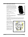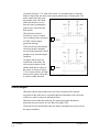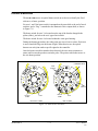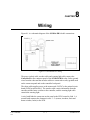
1
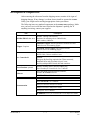
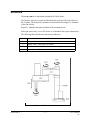
5%14#/'4"36 7UGTIU"/CPWCN Catalog # 100067 Rev.B 9#40+0)# 6JG"5%14#/'4"36"41$16"KU" �)'4175 CPF"ECP"ECWUG"UGXGTG"KPLWT[0 75'"9+6*"':64'/'"%#76+100 5GV"WR"C"RTQVGEVKXG"UETGGP"QT"IWCTFTCKN CTQWPF"VJG"TQDQV"VQ -''2"2'12.'"#9#; HTQO"KVU"YQTMKPI"TCPIG0 Copyright © 1996–1999 Eshed Robotec (1982) Limited. Catalog # 100067 Rev.B ISBN 965-291-069-4 (March 1996) May 1999 Reprinted/PDF version Every effort has been made to make this book as complete and accurate as possible. However, no warranty of suitability, purpose, or fitness is made or implied. Eshed Robotec is not liable or responsible to any person or entity for loss or damage in connection with or stemming from the use of the software, hardware and/or the information contained in this publication. Eshed Robotec bears no responsibility for errors which may appear in this publication and retains the right to make changes to the software, hardware and manual without prior notice. SCORBOT is a registered trademark, and ACL is a trademark, of Eshed Robotec (1982) Ltd. Read this manual thoroughly before attempting to install or operate the robot. If you have any problems during installation or operation, call your agent for assistance. Save the original carton and all packing material. You may need them later for shipment. Table of Contents CHAPTER 1 Unpacking and Handling Unpacking and Handling the Robot . . . . . . . . . . . . . 1-1 Repacking for Shipment . . . . . . . . . . . . . . . . . . . 1-1 Acceptance Inspection . . . . . . . . . . . . . . . . . . . . 1-2 CHAPTER 2 Specifications Structure . . . . . . . . . . . . . . . . . . . . . . . . . . . 2-2 Work Envelope . . . . . . . . . . . . . . . . . . . . . . . . 2-3 CHAPTER 3 Safety Precautions . . . . . . . . . . . . . . . . . . . . . . . . . 3-1 Warnings . . . . . . . . . . . . . . . . . . . . . . . . . . . 3-2 CHAPTER 4 Installation Preparations . . . . . . . . . . . . . . . . . Controller and Computer/Terminal Setup Robot Setup . . . . . . . . . . . . . . . SCORA-ER 14 Installation . . . . . . . . . . Controller Installation . . . . . . . . . . Robot Installation . . . . . . . . . . . . Homing the Robot . . . . . . . . . . . . Gripper Installation . . . . . . . . . . . . . . Pneumatic Gripper . . . . . . . . . . . . Servo Gripper . . . . . . . . . . . . . . Activating the Gripper . . . . . . . . . . CHAPTER 5 User’s Manual 9603 . . . . . . . . . . . . . . . . . . . . . . . . . . . . . . . . . . . . . . . . . . . . . . . . . . . . . . . . . . . . . . . . . . . . . . . . . . . . . 4-1 4-1 4-1 4-2 4-2 4-2 4-4 4-5 4-5 4-7 4-8 Operating Methods Software . . . . ACL . . . . ATS . . . . ACLoff-line . SCORBASE Teach Pendant . CHAPTER 6 . . . . . . . . . . . . . . . . . . . . . . . . . . . . . . . . . . . . . . . . . . . . . . . . . . . . . . . . . . . . . . . . . . . . . . . . . . . . . . . . . . . . . . . . . . . . . . . . . . . . . . . . . . . . . . . . . . . . . . . . . . . . . . . . . . . . . . . . . . . . . . . . . . . . . 5-1 5-1 5-1 5-2 5-2 5-2 Axes 1 and 2 . . . . . . . Axis 3 . . . . . . . . . . Axis 4 . . . . . . . . . . Motors . . . . . . . . . . DC Motor Structure . SCORA-ER 14 Motors Harmonic Drive Gear . . . Pulleys and Timing Belt . . . . . . . . . . . . . . . . . . . . . . . . . . . . . . . . . . . . . . . . . . . . . . . . . . . . . . . . . . . . . . . . . . . . . . . . . . . . . . . . . . . . . . . . . . . . . . . . . . . . . . . . . . . . . . . . . . . . . . . . . . . . . . . . . . . . . . . . . . . . . . . . . 6-1 6-2 6-2 6-3 6-4 6-5 6-6 6-8 Drive System - vii - SCORA-ER 14 Ball Bearing Screw Worm Gear . . . . Ball Bearing Spline Axis Gear Ratios . CHAPTER 7 . . . . . . . . . . . . . . . . . . . . . . . . . . . . . . . . . . . . . . . . . . . . . . . . . . . . . . . . . . . . . . . . . . . . . . . . . . . . . . . . . . . . 6-9 6-10 6-10 6-11 . . . . . . . . . . . . . . . . . . . . . . . . . . . . . . . . . . . . . . . . . . . . . . . . . . . . . . . . . . . . . . . . . . . . . . . . . . . . . . . . 7-1 7-3 7-4 7-5 7-6 Position and Limit Devices Encoders . . . . . . . . . . . Encoder Resolution . . . End of Travel (Limit) Switches Hard Stops . . . . . . . . . . Home Switches . . . . . . . CHAPTER 8 . . . . Wiring Power (Robot) Cable and Connector . . . . . . . . . . . . 8-2 Encoder Cable and Conenctor . . . . . . . . . . . . . . . . 8-3 Warning Light Cable and Connector . . . . . . . . . . . . . 8-4 CHAPTER 8 Maintenance Daily Operation . . Periodic Inspection Troubleshooting . Messages . . . . SCORA-ER 14 . . . . . . . . . . . . . . . . . . . . . . . . . . . . - viii - . . . . . . . . . . . . . . . . . . . . . . . . . . . . . . . . . . . . . . . . . . . . . . . . . . . . . . . . . . . . 9-1 9-2 9-2 9-6 User’s Manual 9603 CHAPTER 1 Unpacking and Handling ‹ Read this chapter carefully before you unpack the SCORA-ER 14 robot and controller. Unpacking and Handling the Robot The robot is packed in expanded foam. Save the original packing materials and shipping carton. You may need them later for shipment or for storage of the robot. The robot arm weighs 35 kilos (77 pounds). Two people are needed in order to lift or move it. Lift and carry the robot arm by grasping its column and/or base. Do not lift or carry the robot arm by its horizontal links. Repacking for Shipment Be sure all parts are back in place before packing the robot. The robot should be repacked in its original packaging for transport. If the original carton is not available, wrap the robot in plastic or heavy paper. Put the wrapped robot in a strong cardboard box at least 15 cm (about 6 inches) longer in all three dimensions than the robot. Fill the box equally around the unit with resilient packing material (shredded paper, bubble pack, expanded foam chunks). Seal the carton with sealing or strapping tape. Do not use cellophane or masking tape. User’s Manual 9603 1-1 SCORA-ER 14 Acceptance Inspection After removing the robot arm from the shipping carton, examine it for signs of shipping damage. If any damage is evident, do not install or operate the SCORA. Notify your freight carrier and begin appropriate claims procedures. The following items are standard components in the SCORA-ER 14 package. Make sure you have received all the items listed on the shipment’s packing list. If anything is missing, contact your supplier. Item SCORA-ER 14 Robot Arm Gripper: 2 options Description Includes: Cabling with air hoses; Hardware for mounting robot: 4 M8x60 bolts; 4 M8 washers; 4 M8 nuts. Pneumatic Gripper includes pneumatic solenoid valve and 6 M4x8 screws for mounting gripper. Electric DC Servo Gripper with encoder includes 4 M4x10 screws for mounting gripper. Includes: Power Cable 100/110/220/240VAC; RS232 Cable; 3 driver cards for 6 axes ACL Controller-B Teach Pendant: optional Software Optional: Emergency By-Pass Plug (required when TP not connected); Additional driver cards for control of up to 12 axes; Auxiliary multiport RS232 board, cable and connectors. Includes: mounting fixture; connector adapter plug. Teach Pendant for Controller-B User’s Manual ATS (Advanced Terminal Software) diskette; includes ACLoff-line software. SCORBASE Level 5 Software diskette SCORA-ER 14 User’s Manual ACL Controller-B User’s Manual Documentation ACL for Controller-B Reference Guide ATS for Controller-B Reference Guide ACLoff-line User’s Manual SCORBASE Level 5 for Controller-B Version Reference Guide SCORA-ER 14 1-2 User’s Manual 9603 CHAPTER 2 Specifications The following table gives the specifications of the SCORA-ER 14 robot arm. Robot Arm Specifications Mechanical Structure Horizontal articulated (SCARA) Arm Length Link 1 Link 2 270mm (10.6") 230mm (9.0") Axis Movement Axis Range Effective Speed Axis 1: Rotation Axis 2: Rotation Axis 3: Translation 288° 218° 182mm 117°/sec 114°/sec 211mm/sec Axis 4: Roll; without gripper cable: or Roll; with gripper cable: unrestricted ±527° 370°/sec Links 1 and 2 combined Maximum Operating Radius End Effector Minimum 230mm (9.06") Maximum 500 mm (19.69") Pneumatic Gripper Electric DC servo Gripper Hard Home Fixed position on all axes Feedback Incremental optical encoders with index pulse Actuators DC servo motors Transmission Harmonic Drive gears Maximum Payload 2 kg (4.4 lb.) Position Repeatability ±0.05mm (±0.002") Weight 30 kg (66 lb.) Ambient Operating Temperature 2°–40°C (36°–104°F) User’s Manual 9603 1.5m/sec 2-1 SCORA-ER 14 Structure The SCORA-ER 14 is a horizontal articulated (SCARA) robot. The first two joints are revolute and determine the position of the end effector in the XY plane. The third joint is prismatic and determines the height (Z coordinate) of the end effector. Figure 2-1 identifies the joints and links of the mechanical arm. Each joint is driven by a servo DC motor via a Harmonic Drive gear transmission. The following table describes the movement of the axes: Axis No. Motion 1 Rotates Link 1 in horizontal (XY) plane. 2 Rotates Link 2 in horizontal (XY) plane. 3 Translates (raises and lowers) the end effector along Z axis. 4 Rotates the end effector. Figure 2-1: SCORA-14 Mechanical Arm SCORA-ER 14 2-2 User’s Manual 9603 Work Envelope The length of the links and the degree of rotation of the joints determine the robot’s work envelope. Figures 2-2 and 2-3 show the dimensions of the SCORA-ER 14, while Figure 2-4 gives a top view of the robot’s work envelope. The base of the robot is normally fixed to a stationary work surface. It may, however, be attached to a slidebase, resulting in an extended working range. Figure 2-2: Dimensions (Side View) User’s Manual 9603 2-3 SCORA-ER 14 Figure 2-3: Dimensions (Top View) Figure 2-4: Working Range (Top View) SCORA-ER 14 2-4 User’s Manual 9603 CHAPTER 3 Safety The SCORA-ER 14 is a potentially dangerous machine. Safety during operation is of the utmost importance. Use extreme caution when working with the robot. Precautions The following chapters of this manual provide complete details for proper installation and operation of the SCORA-ER 14. The list below summarizes the most important safety measures. 1. Make sure the robot base is properly and securely bolted in place. 2. Make sure the robot arm has ample space in which to operate freely. 3. Make sure both the encoder cable and the robot power cable are properly connected to the controller before it is turned on. 4. Make sure a guardrail or rope has been set up around the SCORA-ER 14 operating area to protect both the operator and bystanders. 5. Do not enter the robot’s safety range or touch the robot when the system is in operation. 6. Press the controller’s EMERGENCY switch before you enter the robot’s operating area. 7. Turn off the controller’s POWER switch before you connect any inputs or outputs to the controller. ‹ User’s Manual 9603 To immediately abort all running programs and stop all axes of motion, do any of the following: press the teach pendant’s EMERGENCY button; use the ACL command A <Enter>; press the controller’s red EMERGENCY button. 3-1 SCORA-ER 14 Warnings 1. Do not operate the SCORA-ER 14 until you have thoroughly studied both this User’s Manual and the ACL Controller-B User’s Manual. Be sure you follow the safety guidelines outlined for both the robot and the controller. 2. Do not install or operate the SCORA-ER 14 under any of the following conditions: 3. SCORA-ER 14 • Where the ambient temperature drops below or exceeds the specified limits. • Where exposed to large amounts of dust, dirt, salt, iron powder, or similar substances. • Where subject to vibrations or shocks. • Where exposed to direct sunlight. • Where subject to chemical, oil or water splashes. • Where corrosive or flammable gas is present. • Where the power line contains voltage spikes, or near any equipment which generates large electrical noises. Do not abuse the robot arm: • Do not operate the robot arm if the encoder cable is not connected to the controller. • Do not overload the robot arm. The weight of the payload may not exceed 2kg (4.4 lb.). It is recommended that the workload be grasped at its center of gravity. • Do not use physical force to move or stop any part of the robot arm. • Do not drive the robot arm into any object or physical obstacle. • Do not leave a loaded arm extended for more than a few minutes. • Do not leave any of the axes under mechanical strain for any length of time. Especially, do not leave the gripper grasping an object indefinitely. 3-2 User’s Manual 9603 CHAPTER 4 Installation Preparations Before you make any cable connections, set up the system components according to the following “ Preparation” instructions. Controller and Computer/Terminal Setup Place the controller and computer at a safe distance from the robot—well outside the robot’s safety range. Make sure the setup complies with the guidelines defined in the chapter, “ Safety,” in the ACL Controller-B User’s Manual. Robot Setup Refer to Figures 4-1 and 4-2. 1. Set up the SCORA-ER 14 on a sturdy surface with at least 70 cm of free space all around the robot. 2. Set up the robot so that it faces in the proper direction— towards the application or machine it will serve. 3. Fasten the base of the robot to the work surface with four sets of bolt, washer and nut. Make sure the robot is securely bolted in place. Otherwise the robot could become unstable and topple over while in motion. Figure 4-1: Robot Safety Range User’s Manual 9603 4-1 SCORA-ER 14 4. Set up a guardrail or rope around the SCORA-ER 14 operating area to protect both the operator and bystanders. Figure 4-2: Robot Base Layout SCORA-ER 14 Installation Controller Installation Perform the installation procedures detailed in the following sections of Chapter 2, “ Installation,” in the ACL Controller-B User’s Manual: ‹ • Computer/Terminal–Controller Installation • Power On • Controller Configuration When the Peripheral Setup screen appears at the end of the controller configuration, select Gripper Connection: None. (You will change this setting after the gripper is installed.) Refer to the section, “ Peripheral Devices and Equipment--Robot Gripper,” in the ACL Controller-B User’s Manual. Robot Installation ‹ Before you begin, make sure the controller POWER switch is turned off. Refer to Figures 4-3 and 4-4. Refer also to the wiring information and diagram in Chapter 8. 1. SCORA-ER 14 Connect the safety ground wires: • Unscrew and remove the nuts and washers from the safety ground studs on both the robot and controller connector panels. • Connect the green/yellow wires from both the robot cable and the encoders cable to the safety ground studs on both the robot and controller connector panels. 4-2 User’s Manual 9603 Figure 4-3: Robot Connector Panel • 2. 3. Note: User’s Manual 9603 Figure 4-4: Controller Connector Panel After you have placed the ground wire terminals onto the studs, replace and tighten the washers and nuts. Connect the two cables which connect the robot and the controller. • Plug the the D37 connectors on the encoder cable into the Robot Encoders port on the controller and into the port on the robot’s connector panel. Tighten the retaining screws on the connector. • Plug the 19-pin round connectors on the robot cable into the Robot Power port on the controller and into the port on the robot’s connector panel. Connect the robot warning light to the controller: • Plug the 3-pin round connector on the warning light cable into the Warning Light port on the robot. Connect the red and black wires to any unused relay output terminal: one wire to NO and one wire to C on the same output. • Write a routine which will turn on the output whenever the controller is in CON state and turn off the output whenever the controller is in COFF state. For automatic activation of this routine, include it in the user-reserved ACL program BACKG. Refer to the ACL for Controller-B Reference Guide for more information on BACKG. When disconnecting the robot from the controller, do it in the opposite order: • Disconnect the warning light connections. • Disconnect the power cable connections. • Disconnect the encoders cable connections. • Disconnect the ground wires. 4-3 SCORA-ER 14 Homing the Robot After you have completed the robot installation, execute the robot’s Home routine, as described below. ‹ ‹ The robot must be homed before you mount the gripper. Before you begin the homing procedure, make sure the robot has ample space in which to move freely and extend its arm. 1. Turn on the controller. Turn on the computer. 2. From the ATS diskette or directory, activate the ATS software. Type: ats <Enter> If the controller is connected to computer port COM2, type: ats /c2 3. When the ATS screen and > prompt appear, you may proceed. 4. Give the ACL command to home the robot. Type: home <Enter> The monitor will display: WAIT!! HOMING... During the Home procedure, the robot joints move and search for their home positions in the following sequence: axis 3 (vertical stroke), axis 2, axis 4 (roll) and axis 1. If home is found, a message is displayed: HOMING COMPLETE (ROBOT) If the HOME process is not completed, an error message identifying the failure is displayed. For example: *** HOME FAILURE AXIS 3 If the home switch is found, but not the encoder’s index pulse, the following message is displayed: * * * INDEX PULSE NOT FOUND AXIS 2 SCORA-ER 14 4-4 User’s Manual 9603 Gripper Installation The gripper is attached to the flange at the end of the robot arm whose layout is shown in Figure 4-5. Pneumatic Gripper The pneumatic gripper, shown in Figure 4-6, is controlled by a 5/2 solenoid pneumatic valve which is activated by one of the controller’s relay outputs. The valve may be 12VDC or 24VDC and can draw its power from the controller’s User Power Supply. ‹ The robot must be homed before you mount the gripper. 1. Using a 3mm hex wrench and six M4x8 socket screws, attach the gripper to the robot arm flange. 2. Connect the coiled double hose from the gripper to the quick coupling on the underside of Link 2, as indicated in Figure 4-7. Figure 4-6: Pneumatic Gripper Figure 4-7: Gripper Connectors User’s Manual 9603 Figure 4-5: Gripper Mounting Flange Layout 4-5 SCORA-ER 14 3. 4. Refer to Figure 4-8. • Connect the two transparent 1/4" O.D. hoses from the robot to the CYL ports on the pneumatic valve. • Connect a 5 bar/90 PSI air supply to the IN port on the valve. Refer to Figure 4-9. Connect the valve to the controller’s User Power Supply as follows: • Connect the black wire to a common terminal. • Connect the red wire to the normally open (NO) terminal of any unused relay output. 5. Connect 12VDC or 24VDC (in accordance with your valve’s specification) to the common (C) terminal of the same relay output, as shown in Figure 4-9. 6. Attach the valve to the controller or any other metalic surface by means of the valve’s magnetic base. SCORA-ER 14 Figure 4-8: Pneumatic Solenoid Valve Figure 4-9: Valve— Controller Connections 4-6 User’s Manual 9603 Servo Gripper The electrical servo gripper is shown in the inset in Figure 4-10. ‹ The robot must be homed before you mount the gripper. 1. Using a 3 mm hex wrench and four M4x10 socket screws, attach the gripper to the gripper mounting flange at the end of the robot arm. 2. Connect the gripper cable to the electrical connector on the robot arm. Make sure the connector is oriented as shown in Figure 4-10. 3. Make sure the gripper cable is positioned as shown in both Figure 4-10 and Figure 4-11. Refer to A-A in Figure 4-10. Fit the two cable clamps onto the two gripper cables. Place the clamps on the flange. Fit the spacer on the cable clamp screw, and then tighten the screw onto the flange. 4. Carefully execute the robot HOME command. Stay close to the teach pendant or controller. If the gripper cable becomes entangled or excessively stretched during the homing, abort the procedure immediately. 5. The gripper has a rotation of ±270°. Do not attempt to move the gripper beyond this limit. 6. At the end of each work session (before turning off the controller), or before homing the robot, make sure the gripper’s position is as shown in Figure 4-11. Gripper Mounting Flange Figure 4-10: Connecting Gripper to SCORA-ER 14 User’s Manual 9603 4-7 SCORA-ER 14 Figure 4-11: Connecting Gripper to SCORA-ER 14 ‹ Axis 5 is reserved by default controller configuration for a servo gripper. To connect a different device as axis 5, you must change the system configuration by means of the ACL command CONFIG. Activating the Gripper 1. Activate ATS. Press <Ctrl>+F3 to activate the Peripheral Setup screen. 2. Change the robot gripper definition according to the gripper you have installed. Refer to the section, “ Peripheral Devices and Equipment--Robot Gripper,” in Chapter 2 of the ACL Controller-B User’s Manual. 3. Open and close it in order to verify that it is functioning. The following commands work for both the electric and the pneumatic gripper. PC Type: open <Enter> The gripper opens. Type: close <Enter> The gripper closes. TP Key in: Open/Close The Open/Close key toggles the gripper between its open and closed states. programs you have just written. SCORA-ER 14 4-8 User’s Manual 9603 CHAPTER 5 Operating Methods The SCORA-ER 14 robot can be programmed and operated in a number of ways. The ACL Controller-B User’s Manual includes two chapters which guide you through the basic commands for operating and programming the robot. Software ACL ACL, Advanced Control Language, is an advanced, multi-tasking robotic programming language developed by Eshed Robotec. ACL is programmed onto a set of EPROMs within Controller-B, and can be accessed from any standard terminal or PC by means of an RS232 communication channel. ACL features include the following: Direct user control of robotic axes. User programming of robotic system. Input/output data control. Simultaneous and synchronized program execution (full multi-tasking support). Simple file management. The ACL Reference Guide for Controller-B provides detailed descriptions and examples of the ACL commands and functions. ATS ATS, Advanced Terminal Software, is the user interface to the ACL controller. ATS is supplied on diskette and operates on any PC. The software is a terminal emulator which enables access to the ACL environment from a PC host computer. User’s Manual 9603 5-1 SCORA-ER 14 ATS features include the following: Short-form controller configuration. Definition of peripheral devices. Short-cut keys for command entry. Program editor. Backup manager. Print manager. The ATS Reference Guide for Controller-B is a complete guide to ATS. ACLoff-line ACLoff-line is a preprocessor software utility, which lets you access and use your own text editor to create and edit ACL programs even when the controller is not connected or not communicating with your computer. After communication is established, the Downloader utility lets you transfer your program to the controller. The Downloader detects the preprocessor directives, and replaces them with a string or block of ACL program code. ACLoff-line also enables activation of ATS, Advanced Terminal Software, for on-line programming and system operation. ACLoff-line is described fully in the ACLoff-line User’s Manual. SCORBASE SCORBASE Level 5 is a robot control software package which is supplied on diskette with the controller. Its menu-driven structure and off-line capabilities facilitate robotic programming and operation. SCORBASE runs on any PC system and communicates with ACL, the controller’s internal language, by means of an RS232 channel. The SCORBASE Level 5 for Controller-B Reference Guide provides detailed descriptions and examples of the SCORBASE commands. Teach Pendant The teach pendant is a hand-held terminal which is used for controlling the SCORA-ER 14 robot and peripheral equipment. The teach pendant is most practical for moving the axes, recording positions, sending the axes to recorded positions and activating programs. Other functions can also be executed from the teach pendant. The Teach Pendant for Controller-B User’s Manual fully describes the various elements and functions of the teach pendant. SCORA-ER 14 5-2 User’s Manual 9603 CHAPTER 6 Drive System The SCORA-ER 14 utilizes several different mechanical transmissions for transferring motion from the motors to the joints. The structure and operation of the various components used to drive the SCORA axes are described in this chapter. ‹ Note that the illustrations of components shown in this chapter are for descriptive purposes, and may not be the actual components used in the SCORA-ER 14. ENCODER MOTOR Axes 1 and 2 MOTOR OUTPUT SHAFT The main components of the drive system for axes 1 and 2 are the motor, the coupling and the Harmonic Drive gear, as shown in Figure 6-1. COUPLING H.D. INPUT SHAFT HARMONIC DRIVE GEAR LIMIT SWITCH DISK H.D. OUTPUT Figure 6-1: Drive System Axes 1 and 2 User’s Manual 9603 6-1 SCORA-ER 14 Axis 3 UPPER The drive system for axis 3 produces the linear motion of the Z-axis. Its main components are the motor, pulleys and a timing belt, and a ball bearing lead screw with nut, as shown in Figure 6-2. BEARINGS NUT BALL BEARING LEAD SCREW ENCODER Axis 4 BEARINGS MOTOR The drive system for axis 4 (Z-roll) produces the rotation of the end effector flange. Its main components are the motor, a worm gear and a spline, as shown in Figure 6-3. PULLEYS & TIMING BELT END Figure 6-2: Drive System Axis 3 Figure 6-3: Drive System Axis 4 SCORA-ER 14 6-2 User’s Manual 9603 Motors An electric motor is an actuator—a device which transforms electric power into mechanical power. The motor converts signals from the controller into rotations of its shaft. A robot arm such as the SCORA-ER 14 imposes severe requirements on the actuators, such as the following: • The robot motor must rotate at different speeds, and with a high degree of accuracy. For example, if the robot is to be used for a spray painting application, it must be able to accurately follow the defined path at the specified speed. • The robot motor must allow fine speed regulation so that the robot will accelerate and decelerate as required by the application. • The robot motor must supply large torques throughout its speed range and also when the joint is stationary. • The robot motor must be able to stop extremely quickly without overshooting the target position, and perform rapid changes in direction. • Since mounting motors on the robot arm adds to the robot’s weight and inertia, the robot motors must be light and compact, yet powerful. As shown in Figure 6-4, the motors of the SCORA-ER 14 are located close to the axes they drive. Figure 6-4: Motor Locations in SCORA-ER 14 User’s Manual 9603 6-3 SCORA-ER 14 DC Motor Structure The principles of operation of electrical motors in general, and DC motors in particular, are based on an electrical current flowing through a conductor situated within a magnetic field. This situation creates a force which acts on the conductor. Figure 6-5 shows the basic structure and components of a DC motor comparable to the structure of the motors used in the SCORA-ER 14. This motor has three main components: • Stator: This is a static component which creates the magnetic field. The stator may be a permanent magnet, or an electromagnet consisting of a coil wound around thin iron plates. • Rotor: This is the component which rotates within the magnetic field. The external load is connected to the rotor shaft. The rotor is generally composed of perforated iron plates, and a conducting wire is wound several times around the plates and through the perforations. The two ends of the conductor are connected to the two halves of the commutator, which are connected to the electric current via the brushes. • Brushes: These connect the rotating commutator to the electric current source. Figure 6-5: Basic Structure of a DC Motor SCORA-ER 14 6-4 User’s Manual 9603 SCORA-ER 14 Motors The SCORA-ER 14 uses permanent magnet DC motors to drive the axes. Axes 1 and 2 of the SCORA ER-14 are powered by the motor shown in Figure 6-6. Axes 3 and 4 are powered by the motor shown in Figure 6-7. These motors are able to move at extremely high rates of revolution, to move loads with high torques, and (with encoder attached) to achieve a very high resolution. Motor Specifications Motor Axes 1 and 2 Motor Axes 3 and 4 Peak Rated Torque 143 oz.in 27.8 oz.in Rated Torque 32 oz.in 12.5 oz.in Maximum Operating Speed 4000 rpm 4500 rpm Weight 1.29 k / 2.84 lb 0.28 k / 0.62 lb Figure 6-6: Motor on Axes 1 and 2 Figure 6-7: Motor on Axes 3 and 4 User’s Manual 9603 6-5 SCORA-ER 14 Harmonic Drive Gear The Harmonic Drive transmission used in the SCORA-ER 14, shown in Figure 6-8, offers a very high gear ratio. The Harmonic Drive gears used in the SCORA-ER 14 have four main components: • Circular spline: a solid steel ring, with internal gear teeth, usually fixed to the robot link. • Wave generator: a slightly elliptical rigid disk, which is connected to the input shaft, with a ball bearing mounted on the outer side of the disk. • Flexspline: a flexible, thin-walled cylinder, with external gear teeth, usually connected to the output shaft. • Dynamic spline: a solid steel cylinder, with internal gear teeth. The external gear teeth on the flexspline are almost the same size as the internal gear teeth on the circular spline except there are two more teeth on the circular spline, and the teeth only mesh when the wave generator pushes the flexspline outwards. Because the wave generator is elliptical, the flexspline is pushed out in two places. As the motor rotates the input shaft, the wave generator rotates and the location of meshing teeth rotates with it. However, because there are two less teeth on the flexspline, it has to rotate backwards slightly as the wave generator rotates forwards. For each complete rotation of the input shaft, the flexspline moves backwards by two teeth. Figures 6-9 and 6-10 show the different steps in this process. Figure 6-8: Harmonic Drive Structure SCORA-ER 14 6-6 User’s Manual 9603 As in all gears, the gear ratio of the Harmonic Drive is the ratio of the input speed to the output speed. If the number of teeth on the flexspline is Nf, then for every revolution of the input shaft, the output shaft rotates by 2/Nf of a revolution (that is, two teeth out of Nf teeth). Hence: 1 HD gear ratio = 2 N f Nf = 2 The Harmonic Drive gear ratio for axis 1 and axis 2 of the SCORA-ER 14 is 160:1 Figure 6-9: Operation of the Harmonic Drive Figure 6-10: Operation of the Harmonic Drive User’s Manual 9603 6-7 SCORA-ER 14 Pulleys and Timing Belt The axis 3 transmission contains two pulleys and a timing belt, as illustrated in Figure 6-11. The input pulley is mounted on the motor output shaft and the output pulley is connected to the lead screw. The gear ratio of the belt drive is the ratio of the output pulley to the input pulley, calculated according to the number of teeth on each pulley. The belt drive used in the SCORA-ER 14 has a a ratio of 80:21. Thus, for each rotation (360°) of the input pulley, the output pulley moves 94°, or approximately one-quarter of a rotation. OUTPUT PULLEY INPUT PULLEY Figure 6-11: Pulleys and Timing Belt SCORA-ER 14 6-8 User’s Manual 9603 Ball Bearing Screw A ball bearing lead screw converts the rotation of the motor to the linear motion of the Z-axis. In lead screw transmissions, the screw is rotated by the motor, and the shaft is connected to the nut, or sleeve, as illustrated in Figure 6-12. In the SCORA-ER 14 the screw rotates and the nut travels along the length of the screw. As shown in Figure 6-13, a ball bearing screw thread is actually a hardened ball race. The nut consists of a series of bearing balls circulating in a similar race. The bearing balls are transferred from one end of the nut to the other by return tubes. The low-friction ball-bearing lead screw provides more accurate and enduring performance. The lead screw used in the SCORA-ER 14 has a 16mm lead. That is, for each rotation of the screw, the nut travels a linear distance of 16mm. Figure 6-12: Lead Screw Transmission The lead screw of the SCORA-ER 14 is fitted with a brake which halts motion of the Z-axis when motor power is cut off. Figure 6-13: Ball Bearing Screw User’s Manual 9603 6-9 SCORA-ER 14 Worm Gear A worm gear transmission, shown in Figure 6-14, is used in the SCORA-ER 14 to transfer the rotation of motor 4 to the rotation of the Z-axis. The ratio of a worm gear transmission is defined as: # teeth on worm gear # of starts on worm shaft The worm gear used in the SCORA-ER 14 has 100 teeth and the shaft has two starts. Thus, the worm gear transmission has a ratio of 50:1. Figure 6-14: Worm Gear Transmission Ball Bearing Spline The SCORA-ER 14 uses a ball bearing spline, shown in Figure 6-15, to transmit torque from the worm gear to the Z-axis (slider) shaft, while allowing linear motion of the axis. Ball bearing splines are similar to ball bearing screws in that they both employ the rolling contact principle of balls recirculating in a path between a shaft (spline) and a matching nut (sleeve). In a ball bearing spline, however, the path of the rolling balls in straight, rather than helical. Figure 6-15: Ball Bearing Spline SCORA-ER 14 6 - 10 User’s Manual 9603 Axis Gear Ratios The overall gear ratio of the output shaft which moves the axis is the product of the ratios of the transmissions in each drive. Axes 1 and 2 are driven by Harmonic Drive gears with a gear ratio of 160:1. Thus, one rotation (360°) of the output shaft of motor 1 or 2 moves the axis 2.25°. Axis 3 is driven by a belt drive with a ratio of 80:21, and a lead screw which converts each rotation of the output pulley to a linear movement of 16 mm. Thus, for each rotation (360°) of motor 3 output shaft, the Z-axis will move a linear distance of 4.2 mm. Axis 4 is driven by a worm gear with a ratio of 50:1. Thus, one rotation (360°) of motor 4 output shaft causes the end effector flange to rotate 7.2°. User’s Manual 9603 6 - 11 SCORA-ER 14 Á SCORA-ER 14 6 - 12 User’s Manual 9603 CHAPTER 7 Position and Limit Devices This chapter describes the various elements in the SCORA-ER 14 which play a part in the positioning of the robot arm and the limiting of its motion. ‹ • Encoders • End of Travel Switches • Hard Stops • Home Switches Note that the illustrations of components shown in this chapter are for descriptive purposes, and may not be the actual components used in the SCORA-ER 14. Encoders The location and movement of an axis is commonly measured by an electro-optical encoder attached to the motor which drives the axis. The encoder translates the rotary motion of the motor shaft into a digital signal understood by the controller. Figure 7-1 shows the encoder mounted on a SCORA-ER 14 motor. The encoder used on the SCORA-ER 14 contains a single light emitting diode (LED) as its light source. Opposite the LED is a light detector integrated circuit. This IC contains several sets of photodetectors and the circuitry for producing a digital signal. A perforated, rotating disk is located between the emitter and detector IC. Figure 7-1: SCORA-ER 14 Encoder User’s Manual 9603 7-1 SCORA-ER 14 As the encoder disk rotates between the emitter and detectors, the light beam is interrupted by the pattern of “ bars” and “ windows” on the disk, resulting in a series of pulses received by the detectors. The SCORA-ER 14 encoders have 512 slots, as shown in Figure 7-2. An additional slot on the encoder disk is used to generate an index pulse (C-pulse) once for each full rotation of the disk. This index pulse serves to determine the home position of the axis. Figure 7-2: SCORA-ER 14 Encoder Disk The photodetectors are arranged so that, alternately, some detect light while others do not. The photodiode outputs are then fed through the signal processing circuitry, resulting in the signals A, A, B, B, I and I, as shown in Figure 7-3. Comparators receive these signals and produce the final digital outputs for channels A, B and I. The output of channel A is in quadrature with that of channel B (90° out of phase), as shown in Figure 7-4. The final output of channel I is an index pulse. When the disk rotation is counterclockwise (as viewed from the encoder end of the motor), channel A will lead channel B. When the disk rotation is clockwise, channel B will lead channel A. Figure 7-3: Encoder Circuitry SCORA-ER 14 Figure 7-4: Encoder Output Signals 7-2 User’s Manual 9603 Encoder Resolution From the quadrature signal the SCORA-ER 14 controller measures four counts for each encoder slot, thus quadrupling the effective resolution of the encoder. The resolution of the encoder is expressed as: SE = 360° n Where: SE is the resolution of the encoder. n is the number of counts per encoder revolution. The encoders used in the SCORA-ER 14 have 512 slots, generating 2048 counts per motor revolution. The encoder resolution is therefore: 360° SE = 2048 = .176° When the encoder resolution is divided by the overall gear ratio of the axis, the resolution of the joint is obtained. Since the encoder is mounted on the motor shaft, and turns along with it, the resolution of the joint is expressed as: SE SJOINT = N A X IS Thus, for example, the resolution of joint 2 of the SCORA-ER 14 is therefore as follows: 0.176° SJ2 = 160 = .0011 The resolution is the smallest possible increment which the control system can identify and theoretically control. The accuracy of the axis—that is, the precision with which it is positioned—is affected by such factors as backlash, mechanical flexibility, and control variations. User’s Manual 9603 7-3 SCORA-ER 14 End of Travel (Limit) Switches The SCORA-ER 14 uses limit switches to prevent the joints from moving beyond their functional limits. When a control error fails to stop the axis at the end of its working range, the limit switch serves to halt its movement. The switch is part of an electric circuit within the robot arm, independent of the robot controller. The limit switches used in the SCORA-ER 14 are shown in Figure 7-5. Axes 1 and 2 each has two limit switches—one at each end of the axis’ working range. Figure 7-5: SCORA-ER 14 Limit Switch The limit switches are mounted on a disk which is attached to the robot’s frame, as shown in Figure 7-6. The output shaft of the Harmonic Drive moves relative to the microswitch disk. As the joint moves, a cam on the Harmonic Drive output shaft reaches a point at which it forces the actuating button of the limit switch into a position which activates the switch. Axis 3 has two limit switches—one at the upper limit and one at the lower limit of the axis’ range. The switches are mounted on the bracket alongside the spline (slider). ACTUATING BUTTON LIMIT SWITCH LIMIT SWITCH CAM Axis 4 (roll) has no travel limit switches; it can rotate endlessly. When a gripper is attached to axis 4, its movements are controlled and limited by means of software only (encoder). LIMIT SWITCH DISK HARMONIC DRIVE Figure 7-6: Limit Switch Activation SCORA-ER 14 7-4 User’s Manual 9603 As shown in Figure 7-7A, when limit switch 1 is activated (that is, when the button is depressed), the relay contact opens and the relay is deenergized. The motor cannot move the joint beyond this point. The diode allows the motor to reverse direction, thus permitting the joint to move away from the limit switch. When the limit switch is activated, it causes a control error, resulting in the activation of COFF, and an impact protection message. A CON must be activated and the robot arm must be manually moved (using keyboard or teach pendant) away from the impact condition. As long as the axis has not reached one of its limits, the relay contact remains closed, and the diode has no effect on the circuit, as shown in Figure 7-7B. Current can flow in either direction; the motor is thus able to rotate in either direction. B Figure 7-7: Axis Limit Circuit Hard Stops When the software limits and/or the end of travel switches fail to halt the movement of the robot arm, it is possible that the momentum of the robot arm will drive it until it reaches its mechanical limit. When the joint reaches this hard stop, the impact protection and thermic protection processes detect an error, thus activating COFF. CON must be activated and the robot arm must be manually moved away from the impact condition. User’s Manual 9603 7-5 SCORA-ER 14 Home Switches The SCORA-ER 14 uses an optical home switch on each axis to identify the fixed reference, or home, position. For axes 1 and 2 the home switch is mounted on the same disk as the end of travel switches, and a “ flag” is attached to the Harmonic Drive output shaft, as shown in Figure 7-8. The home switch for axis 3 is located near the top of the bracket alongside the spline (slider), just below the axis’ upper limit switch. The home switch for axis 4 is located within the worm gear housing. During the homing procedure, the robot joints are moved, one at a time. Each axis is moved until the flag cuts the beam of light. When that occurs, the optical detector on each joint sends a specific signal to the controller. Once the home switch location has been detected, the axis motor continues to rotate until its encoder produces an index pulse. The point at which that occurs is the axis home position. HARMONIC DRIVE LIMIT SWITCH LIMIT SWITCH OPTICAL HOME OPTICAL HOME FLAG AXIS NOT AT HOME FLAG AXIS AT HOME Figure 7-8: Home Switch Activation SCORA-ER 14 7-6 User’s Manual 9603 CHAPTER 8 Wiring Figure 8-1 is a schematic diagram of the SCORA-ER 14 cable connections. Figure 8-1: SCORA-ER 14 Cabling The power (robot) cable, encoder cable and warning light cable connect the Controller-B to the connector panel of the SCORA-ER 14 robot. Safety ground wires from the robot and the encoder cables are connected to safety ground studs on the connector panel and on the controller back panel. The robot cable supplies power to the motors and +24VDC to the printed circuit board (PCB) located in link 1. The encoder cable carries information from the encoders and the home switches to the controller, and the warning light cable controls the warning light. A wire braid links the connectors on the panel to the PCB, located in Link 1. A second braid connects the elements in axes 3 – 5 (motors, encoders, limit and home switches, brake) to the PCB. User’s Manual 9603 8-1 SCORA-ER 14 Power (Robot) Cable and Connector The power (robot) cable, which connects the controller to the robot motors, contains 12 leads in 6 pairs. Figure 8-2 shows the Burndy 19 pin female connector that joins the power cable to the connector panel at the base of the robot. The following table describes the connector pin functions and the cable wiring. Figure 8-2. Burndy 19 Pin Connector Robot (Power) Cable and Connector Pin ID SCORA-ER 14 Pin Description Robot Side (J1) A Motor 1 – M Motor 1 + C Motor 2 – L Motor 2 + E Motor 3 – H Motor 3 + B Motor 4 – K Motor 4 + D Motor 5 – J Motor 5 + R +24V to PCB S 24VRET to PCB Wire Type and Color Pin Description Controller Side (P1) black M0_A brown M0_B Twisted Pair black M1_A red M1_B Twisted Pair black M2_A blue M2_B black M3_A yellow M3_B Twisted Pair black M4_A green M4_B Twisted Pair white +24V black 24VRET Twisted Pair Twisted Pair 8-2 User’s Manual 9603 Encoder Cable and Conenctor The encoder cable, which connects the controller to the motor encoders and optical home switches, contains 38 leads in 19 pairs. Only 14 pairs are used. Figure 8-3 shows the D37 female connector that joins the encoder cable to the connector panel at the base of the robot. The following table details the connector pin functions and the decribes the cable wiring. Figure 8-3. D37 Connector Encoder Cable and Connector Pin Description Robot Side (J4) Pin ID Axis 1 +5V – 2 +5V – 5 A1(Encoder Pulse A) 6 B1(Encoder Pulse B) 7 C1(Encoder Index Pulse) 8 COMMON 1 31 H1 (Home) 9 A2 (Encoder Pulse A) 10 B2 (Encoder Pulse B) 11 C2 (Encoder Index Pulse) 12 COMMON 2 32 H2 (Home) 13 A3 (Encoder Pulse A) 14 B3 (Encoder Pulse B) 15 C3 (Encoder Index Pulse) 16 COMMON 3 33 H3 (Home) User’s Manual 9603 1 2 3 Wire Type and Color Pin Description Controller Side (J2) Twisted Pair red +5V black +5V Twisted Pair brown CHA 0 black CHB 0 Twisted Pair brown CHC 0 red COMMON 0 Twisted Pair white MSWITCH 0 Twisted Pair red CHA 1 white CHB 1 Twisted Pair red CHC 1 blue COMMON 1 Twisted Pair black MSWITCH 1 Twisted Pair orange CHA 2 black CHB 2 orange CHC 2 red COMMON 2 blue MSWITCH 2 Twisted Pair Twisted Pair 8-3 with J2 – 32 with J2 – 31 with J2 – 34 SCORA-ER 14 Encoder Cable and Connector Pin ID Pin Description Robot Side (J4) 17 A4 (Encoder Pulse A) 18 B4 (Encoder Pulse B) 19 C4 (Encoder Index Pulse) 20 COMMON 4 34 H4 (Home) 21 A5 (Encoder Pulse A) 22 B5 (Encoder Pulse B) 23 C5 (Encoder Index Pulse) 24 COMMON 5 35 H5 (Home) Axis Wire Type and Color yellow CHA 3 black CHB 3 yellow CHC 3 red COMMON 3 Twisted Pair black MSWITCH3 Twisted Pair green CHA 4 black CHB 4 green CHC 4 red COMMON4 green MSWITCH4 Twisted Pair 4 5 Pin Description Controller Side (J2) Twisted Pair with J2 – 33 Twisted Pair Twisted Pair with free yellow Warning Light Cable and Connector The warning light cable which connects the controller to the warning light contains three leads. Figure 8-4 shows the Amphenol three pin female connector that joins the warning light cable to the panel at the base of the robot. Figure 8-4. Amphenol 3 Pin Connector The following table details the warning light cable and connector. Warning Light Cable and Connector Pin # SCORA-ER 14 Pin Description Robot Side (J3) Wire Color Pin Description Controller Side 1 NO red NO 2 COM black COM 8-4 User’s Manual 9603 CHAPTER 8 Maintenance The maintenance and inspection procedures recommended below will ensure the best possible performance of the robot over an extended period. Daily Operation At the start of each working session, check the robot and controller, in the following order: 1. 2. 3. User’s Manual 9603 Before you power on the system, check the following items: • The installation meets all safety standards. • All cables are properly and securely connected. Cable connector screws are fastened. • The gripper is properly connected. The air supply (for a pneumatic gripper) is functioning properly. • Any peripheral devices or accesssories which will be used, such as the teach pendant or a remote emergency button, are properly connected to the controller. After you have powered on the system, check the following items: • No unusual noises are heard. • No unusual vibrations are observed in any of the robot axes. • There are no obstacles in the robot’s working range. Bring the robot to a position near home, and activate the Home procedure. Check the following items: • Robot movement is normal. • No unusual noise is heard when robot arm moves. • Robot reaches home position in every axis. 9-1 SCORA-ER 14 Periodic Inspection The following inspections should be performed regularly: • Check robot mounting bolts for looseness using a wrench. Retighten as needed. • Check all visible bolts and screws for looseness using a wrench and screwdriver. Retighten as needed. • Check cables. Replace if any damage is evident. The following robot components may require replacing after prolonged use of the robotic arm causes them to wear or fail: DC Servo Motors Motor Brushes Timing Belts V-Rings Harmonic Drives Cross-Roller Bearings Troubleshooting Whenever you encounter a problem with your system, try to pinpoint its source by exchanging the suspected faulty component—for example, robot, controller, teach pendant, cable—with one from a functioning system. In general, when trying to determine the source of a malfunction, first check the power source and external hardware, such as controller switches, LEDs and cable connections. Then check fuses; you may also open the controller to check components, according to the procedures and instructions detailed in the Controller-B User’s Manual. In addition, make sure the controller is properly configured for the robot and gripper, the software commands have been correctly issued, and system parameters are properly set. All troubleshooting procedures described in the section can be performed by the user. ‹ Do not attempt to open the robot arm. There are no user-serviceable parts inside. If you are unable to determine and/or correct the problem, contact your service representative. Only qualified technicians may remove and/or replace robot components. SCORA-ER 14 9-2 User’s Manual 9603 1. 2. 3. User’s Manual 9603 Controller’s MOTORS switch does not turn on; the green LED does not light. • Make sure the Emergency button is released. • Turn off the controller, disconnect it from the power source, and open the cover. • Check the 0.5A (SB) fuse (marked FAN/POWER/RELAYS) Controller functioning, but the robot cannot be activated. • Make sure an obstacle is not blocking the robot. • Make sure the controller’s MOTORS switch is on and the green LED is lit. • Make sure the controller is in the control off (COFF) state. Then activate the control on (CON) state from PC or TP. • Make sure all robot and encoder cables are properly connected. • Check driver card fuses. Each driver card has a pair of LEDs and a pair of fuses (accessible from controller back panel). The upper LED and fuse correspond to the axis number at the top of the card; the lower LED and fuse correspond to the axis number at the bottom of the card. Both LEDs on each card in use should be lit, indicating that power is being supplied to the axis driver. If one of the LEDs is not lit, remove the fuse for the corresponding axis and examine it. (To remove the fuse, press it in and rotate counter-clockwise.) Robot does not find Home position in one or all of the axes. • Make sure the homing command was properly issued. • Make sure all robot and encoder cables are properly connected. • If the robot has just undergone maintenance or repair, use the command ZSET. Then issue the home command. • Make sure system homing parameters have not been erased. Make sure system homing parameters are properly set. Refer to the ACL Reference Guide. • Check whether the optical home switch for this axis is functioning. Manually move the faulty axis (from teach pendant or keyboard) and check the value of system variable HS[n] (where n is the index of the axis). The value of HS will change to either 1 or 0 (defined by parameter 560+axis) when the home switch is detected. To help you perform this test, prepare and continuously run a simple ACL program, as follows: 9-3 SCORA-ER 14 LABEL 1 PRINTLN HS[n] DELAY 20 GOTO 1 If the value of HS does not change, possible causes: Faulty arm circuitry. Faulty optical switch; optical switch not properly mounted. Faulty driver circuitry Problem in controller power supply unit +5V1. 4. 5. SCORA-ER 14 One of the axes does not function. • Check the driver card LED for this axis at the back of the controller. If the LED is not lit, check the corresponding fuse. • Check the motor drive circuitry. • Check the encoder: Enter the command SHOW ENCO to display the encoder readings. Enter the command COFF (to disable servo control) and then physically move the axis in question in both directions. The encoder reading should rise for rotation in one direction and fall for rotation in the opposite direction. If this does not occur, there is a problem in the encoder or its circuitry. If the encoder readings do not change, check whether the encoder connector is properly connected to the rear controller panel. The problem may be caused by faulty encoder connectors on the robot’s internal PCB’s. Motors suddenly stop. No message on screen. No response to keyboard entries. • Check the power source. • Make sure the MOTORS power switch is on; make sure the Emergency button is not depressed. • Turn off the controller and open up the cover. Turn on the controller. Check the yellow “ watchdog” LED on the main board. If it is lit, it indicates that that one of the following fuses on the power supply unit has blown out: +12VA, –12VA, +12VDR, –12VDR. Turn off the controller and disconnect it from the power source. Check each of these four fuses. Replace the blown fuse. 9-4 User’s Manual 9603 6. Errors in the repeatability of the robot. • Try to identify the faulty axis. If many or all axes are faulty, look for an electrical noise source in your environment. • Check the controller’s ground and the robot’s ground connection to the safety ground terminal at the back of the controller. • Check the encoder. Bring the robot to a starting position. Using a pencil, draw a fine, continuous line on the robot which crosses from the cover of one link to the cover of the adjacent link at the joint in question. Enter the command SHOW ENCO to display the encoder readings. Enter the command COFF (to disable servo control) and then physically move the axis to another position. Then return to the starting position marked by the line you drew. Check the encoder reading for the axis again. It should be within 5 counts of the previous reading; if not, the encoder needs to be replaced. 7. 8. Unusual noise. • Loose screws. • Poor lubrication. • Ratcheting. • Worn motor brushes. • Worn timing belt. • Damaged harmonic drive. Unusual smell. • 9. User’s Manual 9603 A motor has burnt out and needs to be replaced. Axis/axes vibrating, too weak to carry load, motion not smooth, or jerks during or at end of motion. • System parameters are not properly adjusted. Refer to the ACL Reference Guide. • Problem in axis driver card(s) in the controller. Refer to the Controller-B User’s Manual. 9-5 SCORA-ER 14 10. Pneumatic gripper does not respond. • Check that all air hoses are connected properly. • Make sure the gripper is connected to the proper controller output. • Check the relay output to which the gripper is connected. Check whether the relays have been switched (LED is lit): In output OFF, NC is shorted to COM, NO is disconnected from COM. In output ON, NO is shorted to COM, NC is disconnected from COM. If outputs have not been switched, check the flat cable in the controller connecting the main board (J17) and the I/O card. Messages Following is a alphabetical listing of system messages which indicate a problem or error in the operation of the robot arm. Refer to the ACL Reference Guide for additional error messages. Axis disabled. (1) A movement command could not be executed because servo control of the arm has been disabled (COFF). (2) A previous movement of the arm resulted in an Impact or Trajectory error, thereby activating COFF and disabling the arm. Check the movements of the robot, and correct the command(s). CONTROL DISABLED. Motors have been disconnected from servo control. Possible causes: (1) COFF (control off) command was issued. (2) CON (control on) has not been issued; the motors have not been activated. (3) A previous error (such as Impact Protection, Thermic Overload or Trajectory Error) activated COFF, thereby disabling the arm. *** HOME FAILURE AXIS n. The homing procedure failed for the specified axis. Possible causes: (1) The home microswitch was not found. (2) The motor power supply is switched off. (3) Hardware fault on this axis. Home on group/axis not done. You attempted to move the arm to a recorded positions, or to record a position, before homing was performed on the group or axis. SCORA-ER 14 9-6 User’s Manual 9603 *** IMPACT PROTECTION axis n The controller has detected a position error which is too large. The system aborted all movements of that axis group, and disabled all axes of that group. The user routine CRASH, if it exists, has been executed. Possible causes: (1) An obstacle prevented the movement of the arm. (2) An axis driver fuse has blown. (3) The motor power switch is turned off. (4) An encoder fault. (5) A mechanical fault. (6) The axis is not connected. Determine and correct the cause of the position error. Then reenable servo control of the motors (CON), and restart the program. INDEX pulse not found axis n The index pulse of the encoder was not found during the homing of the specified axis. Possible causes: (1) The distance between the index pulse and the home switch transition position has changed, due to a mechanical fault on the axis or a maintenance procedure (such as replacement of the motor, motor belt, encoder, or gear). Enter the command ZSET. Then retry homing. (2) Index pulse faulty. Check the encoder and wiring. *** LOWER LIMIT AXIS n. During keyboard or TP manual movement of the specified axis, its encoder attained its minimum allowed value. Move the axis in the opposite direction. Motor power switch is OFF. Be sure the controller’s MOTORS switch is on. Activate CON. Then repeat the motor or movement command. No hard homing axis n. The specified axis has not been configured for hard homing. Use the HOME command (instead of HHOME). OR Check the type of homing suitable for that axis. If necessary, change the system parameters to allow hard homing of the axis. No homing. The homing parameters for the axis (PAR 460+axis and PAR 600+axis) are set to 0; as a result, the homing procedure will not be performed on the axis. User’s Manual 9603 9-7 SCORA-ER 14 *** OUT OF RANGE axis n An attempt was made to record a position (HERE, HEREC, etc. ) while the robot arm was out of its working envelope. Manually move the arm to a location within its working envelope. Then repeat the command. *** THERMIC OVERLOAD axis n Through a software simulation of motor temperature, the system has detected a dangerous condition for that motor. The system aborted all movements of that axis group, and disabled all axes of that group. The user routine CRASH, if it exists, has been executed. Possible causes: (1) The arm attempted to reach a position, which could not be reached due to an obstacle (for example, a position defined as being above a table, but actually slightly below the table’s surface). The impact protection is not activated because the obstacle is close to the target position. However, integral feedback will increase the motor current and the motor will overheat, subsequently causing the Thermic Protection to be activated. (2) An axis driver is faulty or its fuse has blown. (3) The robot arm is near to the target position, but does not succeed in reaching it, due to a driver fault. The software will then detect an abnormal situation. (4) The Thermic Protection parameters are improperly set, or have been corrupted by improper loading of parameters. Check the positions, the axis driver card and parameters. Reenable servo control of the motors ( CON ). *** TOO LARGE SPEED axis n. Possible causes: (1) The controller has detected a movement which is too fast; that is, the required displacement of the encoder, as calculated from the speed limit parameter, PAR 180+axis, is too great. (2) Since the trajectory is not calculated prior to a linear or circular movement, the linear or circular movement may cause one of the joints to move too fast. Lower the value of speed for that movement. SCORA-ER 14 9-8 User’s Manual 9603 *** TRAJECTORY ERROR ! During movement, the robot arm reached its envelope limits, and the system aborted the movement. This may occur when executing the following types of movements: linear (MOVEL), circular (MOVEC) , MOVES, and SPLINE. Since the trajectory is not computed prior to motion, the movement may exceed the limits of the working envelope. Modify the coordinate values of the positions which define the trajectory. *** UPPER LIMIT AXIS n During keyboard or TP manual movement of the specified axis, its encoder attained its maximum allowed value. Move the axis in the opposite direction. User’s Manual 9603 9-9 SCORA-ER 14