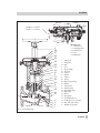
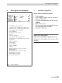
1
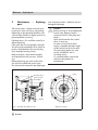
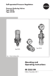
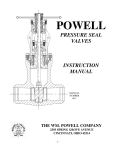
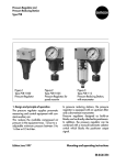
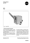
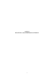
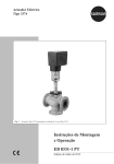
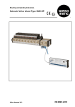
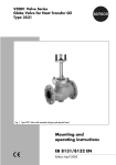
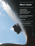
Pneumatic On-off Valve
Type 3351
Fig. 1 · Type 3351
Mounting and
Operating Instructions
EB 8039 EN
Edition January 2005
Contents
Contents
Page
1
Design and principle of operation . . . . . . . . . . . . . . . . . . . 4
2
2.1
Installation . . . . . . . . . . . . . . . . . . . . . . . . . . . . . . . 4
Direction of flow . . . . . . . . . . . . . . . . . . . . . . . . . . . . 4
3
3.1
3.2
3.3
3.4
3.5
Maintenance – Replacing parts . . . . . . . . . . . . . . . . . . . . . 6
Disassembly for valves in DN 15 to 80 . . . . . . . . . . . . . . . . . 7
Reassembling valve in DN 15 to 80 . . . . . . . . . . . . . . . . . . . 8
Disassembly for valves in DN 100 . . . . . . . . . . . . . . . . . . . . 9
Reassembling valve in DN 100 . . . . . . . . . . . . . . . . . . . . . 9
Function test . . . . . . . . . . . . . . . . . . . . . . . . . . . . . 10
4
Description of nameplate . . . . . . . . . . . . . . . . . . . . . . . 11
5
Customer inquiries . . . . . . . . . . . . . . . . . . . . . . . . . . 11
Note!
Non-electrical actuators and valves do not have their own potential ignition source
according to the risk assessment in the rare incident of an operating fault, corresponding to
EN 13463-1: 2001 paragraph 5.2, and therefore do not fall within the scope of the
European Directive 94/9/EC.
Refer to paragraph 6.3 of EN 60079-14:1977 VDE 0165 Part 1 concerning connection to
equipotential bonding system.
2
EB 8039 EN
Safety instructions
General safety instructions
4 The control valve may only be mounted, started up or serviced by fully
4
4
4
trained and qualified personnel, observing the accepted industry codes and
practices. Make sure employees or third persons are not exposed to any
danger. All safety instructions and warnings in these mounting and
operating instructions, particularly those concerning assembly, start-up and
maintenance, must be observed.
The control valves fulfill the requirements of the European Pressure
Equipment Directive 97/23/EC. Valves with a CE marking have a
declaration of conformity that includes information about the applied
conformity assessment procedure.
The corresponding declaration of conformity can be viewed and
downloaded on the Internet at http://www.samson.de.
For appropriate operation, make sure that the control valve is only used in
areas where the operating pressure and temperatures do not exceed the
operating values which are based on the valve sizing data submitted in the
order. The manufacturer does not assume any responsibility for damage
caused by external forces or any other external influence! Any hazards
which could be caused in the control valve by the process medium,
operating pressure, signal pressure or by moving parts are to be prevented
by means of the appropriate measures.
Proper shipping and appropriate storage of the control valve are assumed.
Caution!
4 For installation and maintenance work on the valve, make sure the relevant
4
section of the pipeline is depressurized and, depending on the process
medium, drained as well. If necessary, allow the control valve to cool down
or warm up to reach ambient temperature prior to starting any work on the
valve.
Prior to performing any work on the valve, make sure the supply air and
control signal are disconnected or blocked to prevent any hazards that
could be caused by moving parts.
EB 8039 EN
3
Design and principle of operation
1
Design and
operation
principle
of
The Type 3351 Pneumatic Control Valve
consists of an on-off valve and a diaphragm
actuator which can be additionally
equipped with a handwheel.
Depending on the whether the control valve
is designed for Fail Close action or Fail
Open action, the control valves can differ in
the design of valve seat as well as the arrangement and design of the valve plug.
2
Any installation position can be chosen,
however, we recommend horizontal installation with the actuator on top to simplify any
maintenance procedures, when required.
Note!
The valve must be installed free of
stress.
If necessary, support the piping near
the connections. Never attach
supports to the valve or actuator.
Valve with Fail Close action:
The spring (5.5) closes the valve when the
pressure acting on the actuator diaphragm
(5.4) is reduced and upon supply air failure.
The valve opens when the diaphragm (5.4)
is pressurized .
Valve with Fail Open action:
The spring (5.5) opens the valve when the
pressure acting on the actuator diaphragm
(5.4) is reduced and upon supply air failure.
The valve closes when the diaphragm (5.4)
is pressurized.
For versions with handwheel, the
handwheel replaces the supply air function.
In the event of supply air failure, the valve
can be opened with Fail Close action
against the force of the springs (5.5), and it
can be closed for valves with Fail Open action.
Installation
Thoroughly flush the pipeline prior to
installation of the valve so that
welding spatter or other impurities
carried along by the process
medium cannot impair the tight
shut-off function.
2.1
Direction of flow
The direction of the medium flow in the
valve depends on the process medium and
the selected fail-safe action.
For valves with Fail Close action, which are
used to control gases and vapors, the medium must flow against the valve plug (3) in
the closing direction (A → B).
For liquid applications, the medium must
flow into the plug (3) in the opening direction (B → A).
For valves with Fail Open action, the medium flows against the plug (3) in the opening direction (A → B) irrelevant of the process medium type.
4
EB 8039 EN
Installation
Fail Open
Fail Close
5.7
7.3
7.1
Fail Open R = 47 mm
R
Fail Close R = 64 mm
7.2
7
7.4
DN 100 version
6
5.8
5.7
5.4
5.6
5.9
5.5
3.3
3.2
3.1
5
1.2
5.2
4.2
4
1.1
A
B
Fail Open
Fail Close
4.3
4.1
5.1
3
2
3
1
1
1.1
1.2
2
3
3.1
3.2
3.3
4
4.1
4.2
4.3
5
5.1
5.2
7
Valve bonnet
7.1
7.2
7.3
7.4
Diaphragm plate
Nut/Lock nut
Nut
Milled part
Valve body
Flat gasket
Nuts
Seat
Plug assembly
Plug stem
Lock nut
Washer
Packing
Spring
PTFE V-ring packing
Washer
Valve bonnet
Guide bushing
Threaded bushing
5.4 Diaphragm
5.5 Spring
5.6 Spring plate
5.7 Top diaphragm case
5.8 Loading pressure connection
5.9 Nuts, bolts and washers
6
Handwheel (optional)
Fig. 2 · Sectional drawings
EB 8039 EN
5
Maintenance – Replacing parts
3
Maintenance
parts
–
Replacing
The control valve is subject to natural wear
in particular at the seat, plug, and packing.
Depending on the operating conditions, the
valve must be checked at regular intervals to
prevent problems occurring.
If leakage occurs, this could be caused by a
defective packing.
If the valve does not seal properly, the tight
shut-off may be impeded by dirt or other impurities caught between the seat and plug,
or by damaged seating surfaces.
Remove the parts, clean them thoroughly
and replace them with new ones, if necessary.
Before performing any work on the valve,
you must disassemble the control valve.
You only need to remove the top diaphragm
case when the actuator is defective due to a
damaged diaphragm.
Caution!
Before servicing or disassembling the
control valve, depressurize the
concerned section of the plant and
drain it.
Wait until the medium has cooled
down, if necessary.
As valves are not free of dead
cavities, remember that there might
still be residual media in the valve.
This particularly applies for valve
version with bellows seal or
insulating section.
It is recommended to remove the
valve from the pipeline for
maintenance.
Spring
Mounting device
Spacer used for
disassembly
Washer
Fig. 3 · Mounting device DN 15 to 80
6
EB 8039 EN
Alignment of spring
Maintenance – Replacing parts
Note!
Before servicing or disassembling the control
valve, disconnect and shut off the supply air.
The procedures to disassemble the valve
with Fail Close action and the valve with Fail
Open action are not the same due to the
plug arrangement.
A mounting device (see Fig. 3 and Table 1)
is needed as the spring (5.5) in the actuator
is preloaded.
To take out the seat ring, a special seat tool
(Table 1) is necessary.
Refer to Table 2 for the required tightening
torques.
3.1
Disassembly for valves in
DN 15 to 80
1. Remove nuts and bolts on the actuator.
For versions with handwheel, turn the
wheel in order to remove any tension
acting on the spring plate (5.6).
Lift off diaphragm case (5.7) and remove diaphragm.
2. Place spacer (approx. 5 mm) on the
spring plate as shown in Fig. 3.
Place mounting device on top and fasten
using three fastening nuts and bolts.
Tighten nuts so that the spring plate
(5.6) is preloaded evenly. As a result,
the plug (3) starts to move away from
the seat.
3. Loosen threaded bushing (5.2) completely. Spray the lock nut (3.2) stuck to
the plug stem with adhesive as well as
the ends of the plug stem with solvent.
Use a hot-air gun to soften the adhesive
4.
5.
6.
7.
and loosen the lock nut (3.2).
Position socket wrench or hex screwdriver (DN 65/80) and carefully turn the
plug stem clockwise until its height has
changed by approx. 6 mm.
Loosen fastening bolts of the mounting
device as well as the plug stem
step-by-step until the plug stem is unscrewed from out of the spring plate
(5.6).
Remove spring plate and spring, unscrew lock nut (3.2).
Remove valve bonnet (5) from valve
body and carefully pull up, for version
with Fail Close action over the plug
stem, and for version with Fail Open action together with the plug stem.
If you want to replace the seat and/or
the plug for the version with Fail Close
action, the seat needs to be removed.
Position the seat wrench (Table 1) (over
the plug stem for version with Fail Close
action) on the seat, so that its recesses
are aligned with the seat's spigots.
Insert the guide part of the seat wrench
in the body and unscrew seat with a
suitable tool extension.
Thoroughly clean all parts, remove flat
gasket (1.1).
If the packing leaks, unscrew the
threaded bushing (5.2) in the valve bonnet and remove the individual parts,
such as V-ring packing (4.2), washer
(4.3), and spring (4.1).
When replacing the plug with a new
one, the packing rings (4.2) need to be
replaced with new ones as well.
EB 8039 EN
7
Maintenance – Replacing parts
Thoroughly clean all parts as well as the
packing chamber.
3.2
Reassembling valve in DN 15
to 80
1. For version with Fail Close action, first
place the plug in the body, for version
with Fail Open action, push plug into the
valve bonnet.
Carefully degrease the plug stem thread.
2. Apply sealant (order no. 8150-0119) to
the seat and screw it in using the seat
wrench (observe tightening torque according to Table 1.)
3. Packing: first insert spring (4.1) and
washer (4.3) in the packing chamber,
then the V-ring packing parts (4.2) after
applying lubricant (order no.
8150-0111) to them.
Loosely screw in threaded bushing (5.2).
4. Insert flat gasket (1.1) into the body.
Place the valve bonnet (5) on the body,
for version with Fail Close action, lift the
plug stem and carefully guide through
the packing.
Fasten down valve bonnet by tightening
the nuts (1.2) evenly.
Screw lock nut (3.2) onto the plug stem
until the end of the thread, place washer
(3.3) on top.
5. Insert spring (5.5) into the valve bonnet
and align according to Fig. 3.
Screw spring plate (5.6) on the plug
stem by hand, until it rests on the spring.
Align the spring plate cams so that the
8
EB 8039 EN
plate is positioned above the recess of
the diaphragm case.
6. Screw on mounting device. Evenly
tighten fastening bolts until the spring is
preloaded approx. 6 mm by the spring
plate.
7. Apply adhesive (order no. 8121-9014)
to the plug stem thread. Place the socket
wrench or hex screwdriver to turn the
plug stem counterclockwise as far as it
will go.
For version with Fail Close action, continue to preload the mounting device
step-by-step until it's three stop bushings
touch the diaphragm case. For version
with Fail Open action, continue to
preload the mounting device
step-by-step until it has a distance of
approx. 2 mm from the diaphragm
case.
Turn plug in this position counterclockwise as far as it will go, then tighten lock
nut (3.2).
Remove mounting device.
8. Insert diaphragm (5.4), place diaphragm case on top and tighten evenly.
Tighten threaded bushing (5.2) as far as
it will go.
Maintenance – Replacing parts
3.3
Disassembly for valves in
DN 100
1. Remove nuts and bolts on the actuator.
For versions with handwheel, turn the
wheel in order to remove any tension
acting on the diaphragm plate (7.1).
Lift off diaphragm case (5.7).
2. Loosen nut (7.3) and unscrew it while
holding the plug stem stationary at the
milled part with an open wrench
(SW 14).
3- Remove diaphragm plate and springs.
Unscrew nut (7.2) together with lock nut.
4. Carefully pull valve bonnet (7) upwards ,
for version with Fail Close action over
the plug stem, and for version with Fail
Open action together with the plug stem.
5. If you want to replace the seat and/or
the plug for the version with Fail Close
action, the seat needs to be removed.
Position the seat wrench (Table 1) (over
the plug stem for version with Fail Close
action) on the seat so that its recesses
are aligned with the seat's spigots.
Insert the guide part of the seat wrench
in the body and unscrew seat with a
suitable tool extension.
6. Thoroughly clean all parts, remove flat
gasket (1.1).
If the packing leaks, unscrew the
threaded bushing (5.2) in the valve bonnet and remove the individual parts,
such as V-ring packing (4.2), washer
(4.3), and spring (4.1).
When replacing the plug with a new
one, the packing rings (4.2) need to be
replaced with new ones as well.
Thoroughly clean all parts as well as the
packing chamber.
3.4
Reassembling valves in
DN 100
1. For version with Fail Close action, first
place the plug in the body, for version
with Fail Open action, push plug into the
valve bonnet.
2. Apply sealant (order no. 8150-0119) to
the seat and screw it in using the seat
wrench (observe tightening torque according to Table 1.)
3. Packing: first insert spring (4.1) and
washer (4.3) in the packing chamber,
then the V-ring packing parts (4.2) after
applying lubricant (order no.
8150-0111) to them.
Loosely screw in threaded bushing (5.2).
4. Insert flat gasket (1.1) into the body.
Place the valve bonnet (5) on the body,
for version with Fail Close action lift the
plug stem and carefully guide through
the packing.
Fasten down valve bonnet by tightening
the nuts (1.2) evenly.
Screw lock nut (3.2) onto the plug stem
until the end of the thread, place washer
(3.3) on top.
5. Screw nut and lock nut onto the plug
stem according to the dimension R
(Fig. 2) and tighten. On doing so, make
sure the plug is resting on the seat.
EB 8039 EN
9
Maintenance – Replacing parts
6. Insert springs into the valve bonnet and
align the end of the springs towards the
middle.
7. Place diaphragm plate on the end of the
plug stem (3.1), while pulling the plug
stem as far as possible out of the valve.
Screw nut (7.3) on tight, while holding
the plug stem stationary at the milled
part with an open wrench (SW 14).
8. Align the holes in the diaphragm, place
diaphragm case on top and fasten tight
by tightening the bolt (5.9) evenly.
3.5
Valve with Fail Close action:
The valve must be closed when 0 bar air
pressure is applied, it must start to open
when at least 3 bar is applied and be completely open at 6 bar.
Valve with Fail Open action:
The valve must still be open when 0.5 bar
air pressure is applied and completely
closed at 4.5 bar.
Function test
After reassembling the valve, we recommend performing a function test to check
whether the valve functions properly.
To proceed, connect a suitable source of
compressed air to the loading pressure connection on the diaphragm case.
Order no.
Table 1
Nominal size
DN 15...25
1/2”...1”
DN 32...50
1 1/2”...2”
DN 65 and 80
4”
Mounting device
1281-0063
1281-0037
1281-0038
Seat wrench
1281-0040
1281-0041
1281-0042
1281-0043
Wrench extension
Fail Close action
1281-0044
1281-0045
1281-0046
1281-0051 1)
Tightening torque
150 Nm
400 Nm
850 Nm
1050 Nm
Tightening torque
Table 2
Nuts (1.2)
Packing (5.2)
Nuts (5.9)
1)
M10/20 Nm
M12/35 Nm
M16/90 Nm
M20/170 Nm
M20x1.5/20 Nm
M20x1.5/80 Nm
M26x1.5/110 Nm
M26x1.5/110 N
M6/13 Nm
M8/18 Nm
M8/18 Nm
M8/18 Nm
On using a torque multiplier with 1” square end.
10
EB 8039 EN
DN 100
Description of nameplate
4
Description of nameplate
5
Customer inquiries
Please submit the following details:
SAMSON
3 -4
1
7
2
11
5
6
8
9
13
16
1
CE marking or "Art. 3, Abs.3"
(see article 3, § 3 of PED), where applicable
2
Identification no. of notified body, fluid group
and category, where applicable
3
Type designation
4
5
6
7
8
Modification index of valve
Material
Year of manufacture
Nominal size: DIN: DN, ANSI: Size
Permissible excess operating pressure at room
temperature
DIN: bar, ANSI: psi
9 Serial number
11 Flow coefficient:
DIN: KVS, ANSI: CV
13 Sealing:
ME Metal, STV Solid Stellite, ST Stellited,
NI Nickel-plated,
IN with PTFE/stainless steel soft sealing
PT with PTFE soft sealing,
PK with PEEK soft sealing
16 Country of manufacture
4 Order number
4 Type, model number, nominal size and
version of the valve
4 Pressure and temperature of the process
medium
4 Flow rate in m3/h
4 Minimum and maximum signal pressure
4 Has a strainer been installed?
4 Installation drawing
Dimensions and weights
Refer to the Data Sheet T 8039 EN for the
dimensions and weights of the various valve
versions.
Fig. 4 · Valve nameplate
EB 8039 EN
11
EB 8039 EN
S/Z 2005-02
SAMSON AG ⋅ MESS- UND REGELTECHNIK
Weismüllerstraße 3 ⋅ 60314 Frankfurt am Main ⋅ Germany
Phone +49 69 4009-0 ⋅ Fax +49 69 4009-1507
Internet: http://www.samson.de