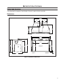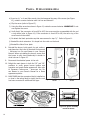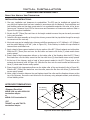
1
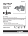
A
W
OWNER’S MANUAL
FOR YOUR SAFETY
Do not store or use gasoline or other flammable
vapours and liquids in the vicinity of this or any
other appliance.
This appliance is only for use with the type of gas
indicated on the rating plate. This appliance is not
convertible for use with other gases, unless a certified
kit is used.
WARNING: If the information in this manual
is not followed exactly, a fire or explosion
may result causing property damage, personal
injury or loss of life. Installation and service
must be performed by a qualified installer,
service agency or the gas supplier.
Tested &
Listed By
C
O-T L
Portland
Oregon USA
US
OMNI-Test Laboratories, Inc,
Report ## 268-S-22-5
Report
268-S-06c-2
N
IO
AT
TR y
IS rant
EG ar
R /w
m
TY o
N .c
A iro
R e nv
Log Set & Nova Valve
R
E33 Gas Insert -
INSTALLER:
Leave this manual with the appliance.
CONSUMER:
Retain this manual for future reference.
WHAT TO DO IF YOU SMELL GAS
• Open windows/extinguish any open
flame.
• Do not try to light any appliance.
• Do not touch any electrical switch
or use any phone in your building.
• Immediately call your gas supplier
from a neighbour’s phone. Follow
the gas supplier’s instructions.
• If you cannot reach your gas
supplier, call the fire department.
Massachusetts installations (Warning): This product must be installed by a licensed
plumber or gas fitter when installed within the Commonwealth of Massachusetts. Other
Massachusetts code requirements: Flexible connector must not be longer than 36in.,
a shut off valve must be installed; only direct vent sealed combustion products are
approved for bedrooms/bathrooms. A carbon monoxide detector is required in all rooms
containing gas fired direct vent appliances. The fireplace damper must be removed or
welded in the open position prior to installation of a fireplace insert.
SHERWOOD INDUSTRIES IS AN ENVIRONMENTALLY RESPONSIBLE COMPANY. THIS MANUAL IS PRINTED ON RECYCLED PAPER.
PLEASE KEEP THESE INSTRUCTIONS FOR FUTURE REFERENCE
50-2517
Safety Precautions
FOR SAFE INSTALLATION AND OPERATION OF YOUR “ENVIRO” HEATER,
PLEASE CAREFULLY READ THE FOLLOWING INFORMATION:
• All ENVIRO gas-fired appliances must be installed
in accordance with their instructions. Carefully read all
the instructions in this manual first. Consult the building
authority having jurisdiction to determine the need for a
permit prior to commencing the installation.
• NOTE: Failure to follow these instructions could
cause a malfunction of the fireplace, which could result in
death, serious bodily injury, and/or property damage.
• Failure to follow these instructions may also void
your fire insurance and/or warranty.
GENERAL
• Installation and repair should be done by a qualified
service person. The appliance should be inspected before
the first use and, at least, annually by a qualified service
person. More frequent cleaning may be required due to
excessive lint from carpeting, bedding material, etc. It
is imperative the control compartments, burners and
circulating air passageways of the appliance be kept
clean.
• Due to high temperatures, the appliance should be
located out of high traffic areas and away from furniture
and draperies.
Children and adults should be alerted to the
hazards of high surface temperatures and should
stay away to avoid burn or clothing ignition.
• Young children should be carefully supervised when
in the same room as the appliance. Toddlers, young
children and others may be susceptible to accidental
contact burns. A physical barrier is recommended if there
are at risk individuals in the house. To restrict access to a
fireplace or stove install an adjustable safety gate to keep
toddlers, young children and other at risk individuals
out of the room and away from hot surfaces. Any safety
screen or guard removed for servicing an appliance must
be replaced prior to operating the appliance.
• Clothing or other flammable materials should not be
placed on or near the appliance.
WARNING
HOT GLASS WILL
CAUSE BURNS
DO NOT TOUCH
GLASS UNTIL COOLED.
NEVER ALLOW
CHILDREN TO TOUCH
GLASS.
2
FOR YOUR SAFETY
• Installation and service must be performed by a qualified
installer, service agency or gas supplier.
• This installation must conform to local codes or, in the
absence of local codes, with the National Fuel Gas Code,
ANSI Z223.1/NFPA 54, or the National Gas and Propane
Installation Code, CSA B149.1.
• To prevent injury, do not allow anyone who is unfamiliar
with the stove to operate it.
• To prevent injury, if the pilot or pilot and burners
have gone out on their own, open the glass door and
wait 5 minutes to air out before attempting to relight the stove.
• Always keep the area around these appliances clear of
combustible material, gasoline and other flammable liquids
and vapours.
• These appliances should not be used as a drying rack
for clothing or for hanging Christmas stockings/decorations.
• Due to the paint curing on the stove, a faint odor and
slight smoking will likely be noticed when the stove is first
used. Open a window until the smoking stops.
Always connect this gas stove to a vent system and vent to
the outside of the building envelope. Never vent to another
room or inside the building. Make sure the specified vent
pipe is used, properly sized and of adequate height to
provide sufficient draft. Inspect the venting system annually
for blockage and signs of deterioration.
WARNING: Failure to position the parts in accordance
with the diagrams in this booklet, or failure to use only
parts specifically approved with this appliance, may result in
property damage or personal injury.
WARNING: Do not operate with the glass front removed,
cracked or broken. Replacement of the glass should be done
by a licensed or qualified service person.
• Never use solid fuels such as wood, paper, cardboard,
coal, or any flammable liquids, etc., in this appliance.
• Do not use this appliance if any part has been under
water. Immediately call a qualified service technician to
inspect the appliance and to replace any part of the control
system or any gas control which has been under water.
• Do not abuse the glass by striking it or slamming the
door shut.
• If the E33 unit is pulled out of its installation, and
the vent-air intake system is disconnected for any reason,
ensure that the vent-air intake pipes are reconnected and
re-sealed in accordance to the instructions noted in Initial
Installation - Venting Fireplace Inserts.
Table of Contents
Safety Precautions...........................................................................................................2
Table of Contents.............................................................................................................3
Codes And Approvals.......................................................................................................4
Specifications..................................................................................................................5
Rating Label Location...........................................................................................5
Dimensions..........................................................................................................5
E33 Options Dimensions.........................................................................................6
Operating Instructions....................................................................................................7
Lighting and Turning Off Instructions.....................................................................7
Pilot Light.............................................................................................................8
Venturi Adjustment...............................................................................................8
Normal Sounds During Operation.........................................................................8
Burner Lighting.....................................................................................................9
Blower Speed.......................................................................................................9
Maintenance And Service................................................................................................10
Cleaning The Glass.............................................................................................10
Cleaning The Firebox..........................................................................................10
Replacing The Glass............................................................................................10
Check Pilot and Burner Flames............................................................................10
Glass Door Removal...........................................................................................11
Cleaning The Painted Surfaces............................................................................11
Removing Valve Cover.........................................................................................12
Fuel Conversion..................................................................................................12
Initial Installation...........................................................................................................15
Clearances to Combustibles.................................................................................15
Minimum Fireplace Size.......................................................................................15
Direct Vent Model...............................................................................................15
Preparing Your E33 For Installation........................................................................16
Venting Fireplace Inserts.....................................................................................17
Zero Clearance Fireplace Installation..................................................................18
Direct Vent Vertical Vent Termination...................................................................19
Electrical Requirements.......................................................................................21
Gas Line Connection...........................................................................................22
Adjusting The Pilot Flame....................................................................................24
Secondary Installation....................................................................................................25
Optional Base Shelf & Riser.................................................................................25
Optional 3 and 4 sided Trim-able Panels...............................................................26
Surround Panel Installation..................................................................................27
Firebox Liner and Burner Tube Removal / Installation..............................................28
Log Set and Ember Removal / Installation..............................................................29
Trouble Shooting............................................................................................................32
Parts List.......................................................................................................................33
Parts Diagram - Components..........................................................................................35
Parts Diagram - Options.................................................................................................36
Warranty.......................................................................................................................37
Installation Data Sheet...................................................................................................38
3
Codes And Approvals
DIRECT VENT: This type is identified by the suffix DV. This appliance draws all of its air for combustion from
outside the dwelling, through a specially designed vent pipe system.
This appliance has been tested and approved for installations from 0 feet to 4500 feet (1372 m) above sea level.
In the USA: The appliance may be installed at higher altitudes. Please refer to your American Gas Association
guidelines which state: the sea level rated input of Gas Designed Appliances installed at elevations above 2000
(610 m) feet is to be reduced 4% for each 1000 feet (305 m) above sea level. Refer also to local authorities
or codes which have jurisdiction in your area regarding the de-rate guidelines.
In Canada: When the appliance is installed at elevations above 4500 feet (1372 m), the certified high altitude
rating shall be reduced at the rate of 4% for each additional 1000 feet (305 m).
• This appliance has been tested by OMNI-Test Laboratories and found to comply with the established
VENTED GAS FIREPLACE HEATER standards in CANADA and the USA as follows:
DIRECT VENTED GAS FIREPLACE INSERT HEATER
TESTED TO: ANSI Z21.88-2009/CSA 2.33-2009 VENTED GAS FIREPLACE HEATERS
CAN/CGA 2.17-M91 (R2009) GAS FIRED APPLIANCES FOR HIGH ALTITUDES
CSA P.4.1-09 TESTING METHOD FOR MEASURING ANNUAL FIREPLACE EFFICIENCY
This ENVIRO E33 Fireplace Insert:
• Has been certified for use with either natural or propane gases. (See rating label.)
• Is not for use with solid fuels.
• Is approved for bedroom or bed sitting room. (IN CANADA: must be installed with a permanent wall thermostat
for bedroom installations. Consult the authority having local jurisdiction in your area. IN USA: see current ANSI
Z223.1 for installation instructions.)
• Must be installed in accordance with local codes. If none exist, use current installation code CAN/CGA B149 in
Canada or ANSI Z223.1/NFPA 54 in the USA.
• Must be properly connected to an approved venting system and not connected to a chimney flue serving a
separate solid-fuel burning appliance.
• Is not approved for closet or recessed installations.
IMPORTANT NOTICE (Regarding first fire up): When the unit is turned on
for the first time, it should be turned onto high without the fan on for the first 4
hours. This will cure the paint, logs, gasket material and other products used in
the manufacturing process. It is advisable to open a window or door, as the unit
will start to smoke and can irritate some people. After the unit has gone through
the first burn, turn the unit off, let the unit get cold then remove the glass door
and clean it with a good gas fireplace glass cleaner, available at your local ENVIRO
dealer. See “Door Removal” and “Cleaning The Glass” sections.
4
Specifications
Rating Label Location:
The rating label is located on the left side of the unit, next to the fan controller.
Dimensions:
22.16
9.09
9.06
14.05
11.24
33.00
28.89
27.05
19.78
18.06
17.40
21.55
16.64
LEFT
18.55
FRONT
RIGHT
.25
Figure 1: E33 Exterior Dimensions.
5
Specifications
7
43 8 "
1
26 2 "
3
28 4 "
1
45 2 "
Figure 2: E33 Contemporary Surround with Base Shelf and Riser.
Table 1: E33 Options Dimensions.
Height
Width
6
Regular Surround
26.5” (673 mm)
44 1/8” (1121 mm)
Contemporary Surround
26.5” (673 mm)
44 1/8” (1121 mm)
Extruded Surround
26.5” (673 mm)
44 1/8” (1121 mm)
Trimmable
Surround
Height
38” (965mm)
Width
46” (1168mm)
Height
Width
Depth
Base Shelf
1 ⅝” (41 mm)
45 1/2” (1156 mm)
Bottom 4 ⅞” (112 mm); Top 3 13/16” (97 mm)
Base Shelf Riser
2 ⅛” (54 mm)
44” (1118 mm)
3 11/16” (94 mm)
Operating Instructions
For Your Safety, Read Safety Precautions And Lighting Instructions Before Operating
WARNING: IF YOU DO NOT FOLLOW THESE INSTRUCTIONS EXACTLY A FIRE OR EXPLOSION
MAY RESULT, CAUSING PROPERTY DAMAGE, PERSONAL INJURY OR LOSS OF LIFE.
Lighting and Turning Off Instructions:
FOR YOUR SAFETY READ BEFORE LIGHTING
WARNING:If you do not follow these instructions exactly, a fire or explosion may result causing property damage, personal injury or loss of life
A. This appliance has a pilot which must be lighted by hand. When
lighting the pilot, follow these instructions exactly.
B. BEFORE LIGHTING smell all around the appliance area for gas.
Be sure to smell next to the floor because some gas is heavier
than air and will settle on the floor.
WHAT TO DO IF YOU SMELL GAS:
Do not try to light any appliance. Do not touch any electrical switch; do
not use any phone in your building. Immediately call your gas supplier
from a neighbor's phone. Follow the gas supplier’s instructions. If you
cannot reach your gas supplier, call the fire department.
C. Use only your hand to push in or turn the gas control knob.
Never use tools. If the knob will not push in or turn by hand,
don’t try to repair it. Call a qualified service technician. Force or
attempted repair may result in a fire or explosion.
D. Do not use this appliance if any part has been under water.
Immediately call a qualified service technician to inspect the
appliance and to replace any part of the control system and any
gas control which has been under water.
LIGHTING INSTRUCTIONS
1.
2.
3.
4.
5.
6.
STOP! Read the safety information above on this label.
Set the thermostat to the lowest setting.
Turn off all electric power to this appliance.
Open the front control panel.
Turn off the gas control knob clockwise
to the “OFF” position.
Open door. Wait fIve (5) minutes to clear out any gas. Close door.
Then smell for gas, including near the floor. If you smell gas, STOP!
Follow “B” in the saftey information above on this label. If you don’t
smell gas, go to the next step.
7. Find pilot-located near the center rear of the firebox. Turn the gas
control knob counter-clockwise
to “PILOT”. Push the gas
control in fully and hold, keep knob depressed for about 30 seconds
after the pilot is lit. Release knob. If pilot goes out, repeat steps 4
through 5.
WARNING: This gas valve has a lockout device, which will not allow the
pilot burner to be relit until the thermocouple has cooled.
-If the knob does not pop up when released, stop and immediately call your
service technician or gas supplier.
-If the pilot will not stay lit after several tries, turn the gas control knob
clockwise
to “OFF” and call your service technician or gas supplier.
8. Turn the gas control knob counter clockwise
to the “ON” position.
Flip the burner switch to “ON” then turn the “HI/LOW” knob to the
desired setting.
9. Close the front control panel.
10. Turn on all electric power to the appliance.
11. Set thermostat to desired setting.
TO TURN OFF GAS TO APPLIANCE
4. Turn the gas control knob clockwise
1. Set the thermostat to the lowest setting.
2. Turn off all electric power to the appliance if service is to be performed. 5. Close the front control panel.
3. Open the front control panel and flip burner switch to “OFF”
to the “OFF” position.
C-12454
Figure 3: Lighting instruction label.
7
Operating Instructions
Pilot Light:
1. Turn off the gas to the fireplace. If not recently done, remove the
glass and let the unit air out for at least five (5) minutes to
clear out any gas. Turn on gas to the heater. Leak test all joints with
soapy water. NEVER USE OPEN FLAME FOR LEAK TESTING.
2. Start the pilot by pressing the gas control knob and turning it to PILOT.
While holding the gas control knob in, press the piezo ignitor several
times until the pilot light starts. Hold the gas control knob in for 30
seconds. Check that the pilot has fully engulfed the thermocouple
assembly (see Figure 4).
3. Start the main burner by turning the gas control knob to ON and then
turn the rocker switch to ON. Check that all burner ports have flame.
Thermopile
Thermocouple
Figure 4. Pilot Flame
4. Leak test all gas joints again.
Venturi Adjustment:
The venturi adjustment lever is located on the right side of the unit, behind the surround panel (see
Figure 5). To avoid touching hot surfaces under the unit, use the Door Tool to adjust the venturi.
The venturi allows the amount of air coming into the fireplace to be adjusted in order to accommodate
different climates and venting arrangements. Start the pilot and then the burner. Make sure the pilot
flame is burning normally and none of the burner ports are plugged. Let the fireplace burn for roughly
fifteen (15) minutes and then examine the flames. The
ideal flame will be blue at the base and light orange
above. The flames should be of medium height. If the
flames look like this, no venturi adjustment is needed. If
the flames are fairly short and mostly blue, the fireplace
is getting too much air. Therefore, the air shutter should
be closed (push in) slightly until the correct flames are
achieved. Flames that are very orange, with tall dark
stringy tips are not getting enough air. Open (pull out)
the venturi until the flames clean up. If the venturi is
opened, then closed all the way, and the correct flames
Figure 5: Adjusting the venturi air setting.
cannot be attained, turn off the gas and contact the
dealer.
Warning: Incorrect venturi adjustment may lead to improper combustion, which is a safety hazard.
Contact the dealer if there is any concern about the venturi adjustment.
Normal Sounds During Operation:
Component
Sound & Reason
Fire Box
Creaking when heating up or cooling down.
Burner
Light pop or poof when turned off; this is more common with LP units.
Temperature Sensor
Clinking when it senses to turn the blower on or off.
Pilot Flame
Quiet whisper while the pilot flame in on.
Blower / Fan
Air movement that increases and decreases with the speed of the blower.
Gas Control Valve
Dull click when turning on or off, this is the valve opening and closing.
Table 2: Normal Sound
8
Operating Instructions
Burner Lighting:
A) Make sure the pilot is lit.
B) Turn gas control knob COUNTER CLOCKWISE to ON.
C) Flip the burner switch to ON (Located on the surround panel).
- An alternate switch location is shown in Figure 6.
D) Turn HI/LO knob to the desired flame height.
E) Turn on all electrical power to the unit.
NOTE: Check that all burner holes are lit.
TO TURN GAS FIREPLACE OFF
Flip the burner switch to OFF to turn off burner only.
If the fireplace is to be turned off for the season or for servicing, turn control
knob to OFF, turn the gas shut off valve to OFF. DO NOT FORCE IT. If the
unit is going to be serviced, turn off the electrical power to the unit as well.
NOTE: When the unit is turned on for the first time, it should be turned to
high, with the fan OFF, for the first four (4) hours. This will cure the paint,
logs, gasket material, and other products used in the manufacturing process.
It is advised that a door or window be opened as the unit will smoke, which
can irritate some people. After the unit has gone through the first burn,
turn the unit OFF, including the pilot, and let the unit completely cool. Then
remove the door and clean the glass with a good gas fireplace glass cleaner,
available at your local Enviro dealer. See Maintenance And Service - Cleaning
The Glass and Maintenance And Service - Glass Door Removal.
Alternate Burner Switch Location
Figure 6: E33 Control Panel.
Blower Speed:
The blower will come on only when the fireplace is up to temperature (approximately 15 minutes). The
fan controller knob can be found to the left of the door, behind the surround panel. Rotating the fan
controller knob will change the speed of the fan. To turn the blower off, fully rotate the fan controller
knob counter-clockwise.
9
Maintenance And Service
Warning: Failure to position the parts in accordance with this manual, or failure to use only parts
specifically approved with this appliance, may result in property damage or personal injury.
At least once a year, run through the following procedures to ensure the system is clean and working
properly. Check the burner to see if all the ports are clear and clean. Check the pilot to make sure it is not
blocked by anything. The pilot flame should be blue with little or no yellow on the tips.
The venting system must be periodically examined; it is recommended the examination is done by a
qualified person.
Cleaning The Glass:
When the fireplace is cool, remove the glass door. See Maintenance and Service - Glass Door Removal.
Check the gasket material on the back of the glass, making sure that it is attached and intact.
During a cold start up, condensation will form on the glass. This is a normal condition with all fireplaces.
However, this condensation can allow dust and lint to cling to the glass surface. Initial paint curing of the
appliance can leave a slight film on the glass. The glass will need cleaning after the fireplace has cooled
off from the first burn and about two weeks after first burn. Use a mild glass cleaner and a soft
cloth. Abrasive cleaners will damage the glass and painted surfaces. Depending on the amount
of use, the glass should require cleaning no more than two or three times a season. Do not clean the
glass when it is hot.
Cleaning The Firebox:
Remove the logs carefully, as they are very fragile. Gently remove all the embers and rock wool and
place on a paper towel. Vacuum the bottom of the firebox thoroughly. Carefully clean any dust off the
logs and remove any lint from the burner and pilot. At this time, inspect the burner tube for cracking or
severe warping. If a problem is suspected, contact the dealer. Check the logs for deterioration or large
amounts of soot; a small amount on the logs is normal. Replace the logs and embers as in the Secondary
Installation - Log Set and Ember Installation section. If new/more embers and rock wool are required,
contact your nearest ENVIRO dealer.
Replacing The Glass:
The glass in the fireplace is a high temperature ceramic. If the glass is damaged in any way, a factory
replacement is required (see Parts List). Wear gloves when handling damaged glass door assembly
to prevent personal injury. Do not operate with the glass front removed, cracked or broken. Removal
and replacement of the glass from the door must be done by a licensed or qualified service person.
The glass must be purchased from an ENVIRO dealer. No substitute materials are allowed.
Remove the door (see page 11). The replacement glass will come with a new gasket installed. Remove
any silicone remnants from the door. Apply high temperature silicone to the two vertical faces of the
door and install the new piece of glass with gasket (be sure to maintain edge clearances). Apply even
pressure to the glass to allow the silicone to adhere to the gasket material.
Check Pilot and Burner Flames:
Periodically do a visual check of the pilot flames. One flame should encompass
the ignitor and thermocouple and the other should burn over the burner ports
(see Figure 7). Also check that the burner is operating correctly, refer to Venturi
Adjustment section.
Figure 7: Pilot Flame
10
Maintenance And Service
Glass Door Removal:
Figure 9: Door Removal.
Figure 8: Door Release.
Remove the glass door by placing the hooked end of the door release tool in the hole on the
door latch mechanism (see Figure 8) and pulling the latch out then up. When the two (2)
latches have been released, tilt the bottom of the door forward and then lift up to unhook
the top door tabs (see Figure 9).
Re-assemble in the reverse order.
Warning: Do not touch or attempt to remove the glass if the fireplace is not completely cool.
Never operate the fireplace with the glass removed.
Caution glass may Separate from door.
Cleaning The Painted Surfaces:
Painted surfaces should be periodically wiped with a damp cloth when the unit is cool.
11
Maintenance And Service
Removing Valve Cover:
The valve cover can be removed to access the gas valve.
1. Use a T-20 screwdriver to remove the eight screws that hold down the valve cover shown in Fig. 10.
VALVE
COVER
Figure 10: Valve Cover.
12
Fuel Conversion
TO BE INSTALLED BY A QUALIFIED SERVICE AGENCY ONLY
Please read and understand these instructions before installing.
WARNING: This conversion kit shall be installed by a qualified service agency in accordance
with the manufacturer’s instructions and all applicable codes and requirements of the
authority having jurisdiction. If the information in these instructions is not followed
exactly, a fire, explosion or production of carbon monoxide may result causing property
damage, personal injury or loss of life. The qualified service agency is responsible for
the proper installation of this kit. The installation is not proper or complete until the
operation of the converted appliance is checked as specified in the manufacturer’s
instructions supplied with the kit.
Kit Parts List:
1 - Orifice (NG - #36 DMS or LP #52 DMS)
1 - Conversion label
1 - Installation instruction sheet
Carefully inspect the orifice supplied with this conversion kit. If it has been damaged or is missing,
contact your dealer, distributor or courier company to have it replaced before starting this installation.
NOTE: The unit is shipped from the factory adjusted for use with NATURAL gas.
Conversion Kit Installation:
1. Turn control knob on the gas valve to the “OFF” position and shut the gas supply off at the shut-off
valve upstream of the unit. CAUTION: The gas supply must be shut off prior to disconnecting the
electrical power and before proceeding with the conversion. Allow the valve and unit to cool down
to room temperature.
2. Remove the glass as shown in the Maintenance and Service - Glass Door Removal.
3. Carefully remove the log set and ember material if they are installed.
4. Remove the burner as shown in the Maintenance and Service - Burner Removal.
5.
Convert the burner orifice(s):
a)Remove the main burner orifice with a 3/8” deep socket.
b)Put a bead of pipe-thread sealant on the orifice threads before installing.
c) Install the new orifice(s) from the kit into the orifice mount.
6. Convert the pilot injector:
a)Using a 7/16” wrench, turn the pilot head a ¼ turn counter-clockwise.
b)Push the slider, with your finger or flat head screwdriver.
-Natural gas is marked NAT.
-Propane gas is marked LP with an indicating hole between L and P.
c) Turn the pilot head a ¼ turn clockwise; back to its original position.
7.
Figure 11: Removing
valve cap.
Convert the SIT gas valve:
a) Remove Valve Cover.
b) Remove Hi/Lo valve knob extension by pulling on it. It is pressed onto the gas valve knob.
c) Remove the black protection cap from the HI/LO knob by hand shown in Figure 11.
13
Fuel Conversion
d) Insert a 5/32” or 4 mm Allen wrench into the hexagonal key-way of the screw (see Figure 12), rotate it counter-clockwise until it is free and extract it.
e) Flip the screw (refer to Figure 13).
f) Using the Allen wrench as shown in Figure 12, rotate the screw clockwise. WARNING! Do not
over tighten the screw.
g) Verify that if the conversion is from NG to LPG, the screw must be re-assembled with the red
o-ring visible (refer to Figure 14). If the conversion is from LPG to NG, the red o-ring of the
screw must not be visible.
h) Re-attach the black protection cap that was removed in step “c)”. Refer to Figure 11.
i) Reinstall the knob extension. It is keyed into the notch on the knob.
j) Reinstall the Valve Cover plate.
8. Reinstall the burner, brick panels, log set, embers,
and glass door. Also refer to Secondary Installation
- Installing Log Set and Embers in your Owner’s
Manual. When re-installing the burner, ensure that
the burner to pilot hood relationship is similar to
what is shown in Figure 15.
Loosen
Tighten
9. Reconnect the electrical power to the unit.
10. Relight the main burner in both the “HI” and “LO”
positions to verify proper burner ignition and
operation and proper flame appearance. Also refer
to Secondary Installation - Installing Log Set
and Embers in your Owner’s Manual for a flame
appearance picture.
11. MAKE SURE that the conversion label is installed on
or close to the rating label to signify that the unit
Figure 12: Removing valve Figure 13: Flip valve
has been converted to a different fuel type.
screw.
screw.
Red o-ring
is visible
Red o-ring
is not visible
LPG Configuration
Figure 14: O-ring on valve screw.
14
Figure 15. Ignitor assembly
beside the burner.
Initial Installation
WARNING: Operation of this heater when not connected to a properly installed and maintained
venting system can result in carbon monoxide (CO) poisoning and possible death.
Clearances to Combustibles:
Maintain sufficient clearances for operation, service and
maintenance.
• A minimum distance of 24” (610 mm) is required from
the centerline of the unit to the sidewalls.
• Minimum clearance for any combustible facing is 30”
(762 mm) from the bottom of the unit.
• A 12” (305 mm) wide mantel can be mounted at a
minimum height of 36” (914 mm) from the bottom of
unit.
• If installed at floor level there must be a minimum of
16” (406 mm) of non-combustible material in front of
the unit. If the unit is raised 0-3.9” up, this 16” must
be maintained from the top surface of the combustible
material.
• Unit can be installed with combustible material
underneath, as long as it is raised 4” off the floor.
• Minimum ceiling clearance is 60” from bottom of unit.
12" (305mm) Mantel
Combustible
Facing
30"
(762 mm)
minimum
to bottom
of unit
36"
(914 mm)
minimum
to bottom
of unit
Figure 16: Mantle width and height.
Minimum Fireplace Size:
Table 3: Minimum dimensions of fireplace for E33 to be installed into.
Fireplace Dimensions
Width At Front
32” (813 mm)
Width At Back
20” (508 mm)
Height
20” (508 mm)
Depth
16” (406 mm)
NOTE: Space must be provided for gas line on right side of unit for servicing purposes.
Direct Vent:
WARNING: This appliance has been designed to draw room air for proper heat circulation
from the sides and bottom of the unit, and out the top front. Blocking or modifying these
openings in any way can create hazardous situations.
The vent length for the E33 must be between 8ft (2.44 m) and 30ft (9.14 m).
This model is vented with a 3” intake and a 3” exhaust aluminum or stainless steel flex vent leading into
a vertical termination cap. The flue collars of this model will fit inside of a standard 3” vent and must be
fastened directly to the vent with three screws.. The exhaust vent and air intake are both located on the
top of the unit.
Check periodically that the vents are unrestricted. Also ensure that all direct vent pipes have been
properly sealed and installed after routine inspection or cleaning. The air intake and exhaust pipes must
be installed in the correct locations on the top of the E33.
15
Initial Installation
QUALIFIED INSTALLERS ONLY
Venting Fireplace Inserts:
The ENVIRO E33 may be installed and vented into any solid fuel fireplace that has been installed
in accordance with the National, Provincial/State and local building codes and has been constructed
of non-combustible materials. Before starting, refer to Initial Installation - Preparing Your E33 For
Installation. Please reference the information in Table 4 and Figures 17, and 19.
An approved chimney liner and rain cap must be used. A throat connector or flashing must be installed to
ensure a tight seal, top performance, safety and efficiency. Carefully follow the manufacturer’s instructions
that accompany the chimney liner kit. Use double walled aluminum flex vent (3” flex conversion piece and
4”x 6 5/8” cap) from any of the following approved products; Simpson Dura-Vent (Direct Vent GS) or (ICC
Excel Direct). If necessary, remove the vent collar plate from the top of the insert and connect it securely
to the liner with sheet metal screws.
Check for any tears in the liner at this point. IMPORTANT: The screws that hold the vent collar plate in its
approved position must be installed.
NOTE: If the E33 unit is pulled out of its installation, and the vent air intake system is disconnected
for any reason, ensure that the vent-air intake pipes are re-sealed with high-temperature sealant and
reconnected with three (3) sheet metal screws evenly spaced.
Table 4: Vent termination clearances
Minimum Clearance
Description
3 ft (0.9 m)
Clearance above the highest point where it passes through a roof surface, refer to
Figure 17.
24 in (0.6 m)
Clearance above a roof ridge, any other portion of a building, or any other obstruction within a horizontal distance of 10 feet (3 m), refer to Figure 17.
5 ft (1.5 m)
Clearance for a vent or chimney above either the highest connected appliance
drafthood outlet, or flue collar.
6 ft (1.83 m)
Clearance to mechanical air supply inlet.
3ft (0.9m)
Clearance to each side of center line extended above meter/regulator assembly.
6 ft (1.83 m)
Radial clearance around service regulator vent outlet.
12 in (30 cm)
Clearance above grade, verandah, porch, deck, or balcony.
3 ft (0.9 m)
Clearance to a building opening or combustion air inlet of another appliance, except with the approval of the authority having jurisdiction for the following reduced
clearances.
9 in (0.23 m)
Exception for inputs up to and including 50,000 Btu/h (15kW)
12 in (0.3 m)
Exception for inputs exceeding 50,000 Btu/h (15kW) but not exceeding 100,000
Btu/h (30kW)
2ft (0.6m)
Minimum
3ft (0.9m)
Minimum
16
Roof ridge or
any other portion
of a building
Within
10ft (3m)
Figure 17: Roof Clearances.
Initial Installation
QUALIFIED INSTALLERS ONLY
3" (76mm) Exhaust
3" (76mm) Intake
Figure 18: Generic Vent Cap Underside.
The height for the vent must be between 8 ft (2.44 m) and 30 ft (9.14 m).
Install a sealed vent cap to prevent leakage of room air up through
chimney.
The intake and the exhaust are 3" (76mm).
Measure the height of the chimney beforehand and purchase the
appropriate venting. Never attempt to over-stretch a flexible liner to
accommodate the height of the chimney. Every joint in the venting must
be secured with three (3) #8 x 3/8” HWH sheet metal screws and an
appropriate sealant (either silicone or stove cement).
The flue damper can be fully blocked open or removed for installation of
the E44; the smoke shelves, shields and baffles may be removed if
attached by mechanical fasteners.
The fireplace and fireplace chimney must be clean, in good working order
and constructed of non-combustible materials.
Make sure that all chimney cleanouts are tight fitting and will not permit
air to leak into the chimney.
Refractory, glass doors, screen rails, screen mesh and log grates can be
removed from the fireplace before installing the E44.
Figure 19: Installation of E33 DV .
17
Initial Installation
QUALIFIED INSTALLERS ONLY
Direct Vent Vertical Vent Termination:
INSTALLATION INSTRUCTIONS:
1. Plan your installation and clearances to combustibles. The E33 may be installed and vented into
any solid fuel fireplace that has been installed in accordance with the National, Provincial/State and
local building codes and has been constructed of non-combustible materials. Also refer to the Initial
Installation - Preparing Your E33 For Installation and Clearances to Combustibles sections. Refer to
Figure 19 throughout installation.
2. Stretch the Ø3” (76mm) flex vent liners to the length needed to ensure they can be easily connected
to the vent terminals.
3. Install the flex pipe assembly up through the chimney, ensure that the pipe slides through far enough
to connect onto the vent cap.
4. Most vent caps can be installed onto chimneys with flue openings up to 16” (406mm) x 16” (406mm)
and the actual flashing is 18”x18” (refer to Figure 20). If the chimney is smaller the cap should be
trimmed down and folded over.
5. Apply a bead of stove cement sealant to the top section of the Ø3” (76mm) exhaust vent collar plate.
Slide the Ø3” (76mm) flex vent over the flue collar and secure with three (3) sheet metal screws
evenly spaced.
6. Place a bead of high temperature silicone on the intake collar of the fireplace, slide the Ø3” (76mm)
flex intake liner over the collar, secure the flex liner with three (3) sheet metal screws evenly spaced.
7. At the top of the chimney, apply a bead of stove cement sealant to the Ø3” (76mm) pipe of the
exhaust vent terminal (refer to Figure 18). Slide the flex liner onto the vent terminal and secure with
three (3) sheet metal screws evenly spaced.
8. Place a bead of high temperature silicone on the intake collar of the vent terminal (refer to Figure 18).
Slide the Ø3” (76mm) flex intake liner over the collar, secure the flex liner with three (3) sheet metal
screws evenly spaced.
9. Make a tight connection between the gas fireplace insert flue collar and the fireplace chimney at the
top of the chimney. Secure the vent terminal to the chimney using adequate sealant, and according
to local building codes.
APPROVED TERMINATIONS:
-Simpson Dura-Vent
Trim flashing
as required.
46DVA-VCH cap with 46DVA-GK
termination adapter
or
46DVA-CL33 termination kit
-ICC
TM-4SVT cap with TM-CTA
termination adapter
18"
(457mm)
18"
(457mm)
Figure 20: Generic Vent Cap Dimensions.
18
Initial Installation
QUALIFIED INSTALLERS ONLY
Installing the unit:
• Remove the packaging from the appliance and surround panels; check to make sure there is no
damage. Carefully check the glass door. Do not use the unit if it is damaged. In the event damage is
found, please report it to your dealer as soon as possible.
• Carefully clean the fireplace and flue before installing the stove. Failure to do so may result in fumes
or soot being blown into the room and may cause a fire leading to death or serious injury.
1.Remove the unit from the box and remove all packaging material from the appliance.
2.Remove door. See Maintenance and Service - Glass Door Removal.
3.Remove log and ember set and all wrapping material from the stove. Remove wrapping material from
log and embers and check for any damage. If damage is observed, do not use unit and contact your
local dealer.
4. Check that the chimney clean outs fit properly. The flue damper must be fully blocked open or removed
for installation of the E33; the smoke shelves, shields and baffles may be removed if attached by
mechanical fasteners.
5.If the fireplace opening is lower than 24” (610 mm), remove the vent collar plate from the top of the
insert by unscrewing the single T-20 Torx screw located on the center top of the stove above the door
opening (see Figure 21). Slide the collar plate backwards. Properly secure the vent collar plate to the
flexible vent pipe liner(s) previously installed in the chimney. Be careful not to over-stretch the liner(s).
6.Place the unit part way into the fireplace. Connect the gas line to the ⅜” NPT pipe nipple at the lower
left rear of the unit using locally approved methods (see Initial Installation - Gas Line Connection).
Place the electric cable so it can be connected to the power supply.
7. As you push the unit into its final position in the fireplace, if the vent collar plate was removed, reinstall
it to the stove by sliding it along the top of the unit and secure with the screw previously removed.
8.Adjust the levelling legs to ensure the unit is level and high enough if a base shelf and/or riser is to be
installed. There are four levelling legs on the bottom of the unit (shown in Figure 22).
Vent Collar Screw
Figure 21: Vent Collar Plate Screw Location.
Figure 22: Levelling Legs Position.
19
Initial Installation
QUALIFIED INSTALLERS ONLY
Zero Clearance (ZC) Fireplace Installation:
The metal floor of the ZC solid fuel firebox can be removed to allow the installation of the insert. THE
CLEARANCE TO COMBUSTIBLE MATERIAL UNDER THE INSERT IS 4” (102 mm). YOU MUST USE THE
LEVELING LEGS TO RAISE THE INSERT A MINIMUM OF 4” (102 mm) IF THE UNIT IS TO BE INSTALLED
ON COMBUSTIBLE MATERIAL. IF THE ZERO CLEARANCE FIREPLACE IS installed directly onto a
concrete floor THE MINIMUM CLEARANCE IS NOT APPLICABLE. The optional Base Shelf and Riser
are recommended to fill the space under the unit once raised. The sidewalls and top structure of the
solid fuel firebox cannot be altered with the exception of: removal of dampers, removal of smoke shelf or
baffle, removal of ember catches, removal of log grate, removal of viewing screen/curtain, and removal of
doors. THE ORIGINAL FIREPLACE MAY NEVER BE RETURNED TO SOLID FUEL USE IN THIS CONDITION.
IMPORTANT: If the factory-built fireplace has no gas access hole(s) provided, an access hole of 1.5 inch
(37.5 mm) or less may be drilled through the lower sides or bottom of the firebox in a proper workmanship
like manner. This access hole must be plugged with non-combustible insulation after the gas supply line
has been installed. Cutting any sheet-metal parts of the fireplace, in which the gas fireplace insert is to
be installed, except as tested for the floor is prohibited.
The included label plate shown below must be permanently attached inside the cavity of the fireplace
in a visible location.
WARNING: This fireplace has been converted
for the use with a gas fireplace insert only and
cannot be used for burning wood or solid
fuels unless all original parts have been
replaced, and the fireplace re-approved by the
authority having jurisdiction.
C-11168
Figure 23: Fireplace Altered Plate.
20
Initial Installation
QUALIFIED INSTALLERS ONLY
Electrical Requirements:
The fan will not operate if the appliance is cold. Once the unit is lit and the fan is set to the desired level,
the fan will automatically turn on upon reaching operating temperature. The fan will automatically turn
off after the appliance has cooled down.
Figure 24: Fan wiring diagram.
The fireplace must be electrically connected and grounded in accordance with local codes or, in the
absence of local codes, with the current CSA C22.1 Canadian Electrical Code Part 1, Safety Standards For
Electrical Installations, or The National Electrical Code ANSI / NFPA 70 in the US.
WARNING: The electrical grounding instructions must be followed. The fan kit is equipped with a threeprong (grounding) plug for your protection against shock hazard, and should be plugged directly into a
properly grounded three-prong outlet. DO NOT cut or remove the grounding prong from this plug.
CAUTION: When servicing controls, label all wires prior to disconnection. Wiring errors can cause
improper and dangerous operation. Verify proper operation after servicing.
If any of the original wire as supplied with the appliance must be replaced, it must be replaced with 18
AWG wire with a temperature rating of 105°C
21
Initial Installation
QUALIFIED INSTALLERS ONLY
Gas Line Connection:
WARNING: Only persons licensed to work with gas piping
may make the necessary gas connections to this
appliance.
Gas Line Connection:
• A ⅜” NPT male pipe nipple (supplied with the unit) will
have to be turned into the valve at the lower left side rear
of this fireplace (see Figures 25 and 26). Consult the local
authorities for local codes or use the CAN/CGA B149 (1 or 2)
installation code in Canada. In the US, gas installations follow
either local codes or the current edition of the National Fuel
Gas Code ANSI Z223.1.
• If the factory-built fireplace has no gas access hole(s)
provided, an access hole of 1.5 in (37.5mm) or less may be
drilled through the lower sides or bottom of the firebox in a
proper workmanship like manner. This access hole must be
plugged with non-combustible insulation after the gas supply
line has been installed.
Figure 25: ⅜” NPT Male Pipe Nipple
with Cover Attached.
• A shut-off valve is supplied with this unit.
• The appliance and its appliance main gas valve must be
disconnected from the gas supply piping system during any
pressure testing of that system at test pressures in excess ½
psi (3.5 kPa). The appliance must be isolated from the gas
supply piping system by closing its equipment shutoff valve
during any pressure testing of the gas supply piping system
at test pressures equal to or less than ½ psi (3.5 kPa).
Figure 26: ⅜” NPT Male Pipe Nipple
with Cover Removed.
Table 5: Orifice and Pressure Information.
E33 With Log Set & Nova Valve
Main Burner
Orifice:
Max. Manifold Press:
Min. Manifold Press:
Max. Supply Press:
Min. Supply Press:
Max. Input:
Min. Input:
22
Natural Gas
Propane Gas
#36 DMS
3.8 W.C. (0.95 KPa)
1.2 W.C. (0.30 KPa)
10.5 W.C. (2.62 KPa)
3.5 W.C. (0.87 KPa)
34,000 BTU/hr (9.96 KW)
17,000 BTU/hr (4.98 KW)
#52 DMS
11.0 W.C. (2.74 KPa)
2.7 W.C. (0.67 KPa)
13.0 W.C. (3.24 KPa
8.0 W.C. (1.99 KPa)
31,000 BTU/hr (9.09 KW)
23,000 BTU/hr (6.74 KW)
Initial Installation
QUALIFIED INSTALLERS ONLY
TO TEST VALVE PRESSURES (INPUT RATES):
The pressure taps are located on the front side of the valve (see Figure 27).
1. Remove valve control knobs.
2. Using a long flat bladed screwdriver, turn set screw one (1) turn counter-clockwise to loosen.
3. Place 5/16 in (8 mm) I.D. hose over the pressure taps.
4. Check pressures using a manometer.
5. When finished, remove hose and tighten set screw.
6. Re-install the knobs. Pointer on knobs can be removed and oriented correctly to point at the right
location.
Always check for gas leaks with a soap and water solution after completing the required
pressure test.
NEVER USE AN OPEN FLAME FOR LEAK TESTING.
Table 6: Valve Details.
4
1
5
Item Number
1
2
2
3
4
3
5
Description
Control Knob
(On/Off/Pilot)
Gas Flow Adjustment
Knob
Pilot Adjustment
Screw
Inlet Pressure Test
Point
Outlet Pressure Test
Point
Figure 27: Valve Details.
23
Initial Installation
QUALIFIED INSTALLERS ONLY
Adjusting The Pilot Flame:
The pilot flow adjustment is set to maximum at the factory and should not need to be adjusted. The pilot
flame should envelope ⅜” to ½” (10 to 13mm) of the thermocouple (see Figure 28). However, should
the need arise, follow Steps 1- 2 below.
1. The adjustment screw can be reached through the front of the
unit using a 10 inch flat head screw driver (see Figure 27 for
location on valve).
2. Turn the adjustment screw clockwise to decrease or
counterclockwise to increase pilot flame.
Proper Flame
Adjustment
3/8”-1/2”
(10-13mm)
Thermocouple
Figure 28: Proper Pilot Flame.
24
Secondary Installation
Optional Base Shelf & Riser:
The E33 Base Shelf (1⅝” (41 mm) high) and Base Shelf Riser (2⅛” (54 mm) high) are components that
can be combined to create a riser with an overall height of 23/16” (55 mm). This shelf can be installed
with or without the riser and can be used when the hearth in front of the unit is lower than the fireplace
opening. Additional Base Shelf Risers can be fastened together to increase the height in increments
of 2⅛” (54 mm). This Base Shelf may be used in conjunction with the any of the E33 surround panel
options, and it may also be used with the E33 Trimmable Surround. The Base Shelf and Riser are sold
separately.
Installation:
1. If unit is running, turn it off and
allow it to cool completely.
2. When using more than one riser
each level must be attached
using nine (9) #8 T-20 screws
provided (see Figure 29).
3. If installing with riser(s) the
Base Shelf is to be fastened
to the riser(s) with one T-20
Figure 30: Installing Base Shelf
screw at each end of the back
onto Riser.
(see Figure 30).
4. The leveling legs on the E33 may need to be adjusted to match
the height of the riser and shelf.
5. Center the Base Shelf assembly in front of the unit flush with the
bottom of the unit.
6. Install surround if required.
Figure 29: Combining 2 Base Shelf
Riser.
25
Secondary Installation
Optional 3 Trimmable Panels:
Modifying the Surround Panel:
The E33 Trimmable Surround Panels are large rectangular panels that may be cut for use in cases that a nonstandard fireplace opening (e.g. an arched opening) is to be filled. Optionally this surround can be left uncut
and placed in front of the fireplace opening.
1. Measure the fireplace opening and/or make a template of the fireplace opening.
2. Transfer the measurement to the Trimmable Surround.
3. If desired, offset the measurements by approximately 1/8” (3mm) to the inside; this will allow for the panel
to be placed just inside the fireplace opening for a cleaner appearance.
4. Cut along the preferred line (from direct measurements of offset) and remove any sharp edges.
5. The panel can be touched up with a high temperature metallic black paint available from your dealer.
INSTALLATION:
1. Using the supplied hardware install a Trimmable Panel Bracket, on its short leg, onto each side of the stove
using a T-20 Torx screwdriver. See Figure 31 for the screw location and bracket orientation.
2. Install the Trimmable Panel, with the flanges facing out, onto the stove and in front of the Panel
Brackets by hooking the Panel’s top flange onto the alignment pins on top of the stove (See Figure 31)
3. Using the remaining hardware attach the Trimmable Panel to the Panel Brackets using a T-20 Torx
screwdriver (See Figure 32)
Figure 31: Panel Bracket
Installed and Pin Location
26
Figure 32: Trimmable
Panel Installed
Secondary Installation
Surround Panel Installation:
WARNING: The surround becomes hot when the unit is operating; ensure that the unit is turned off, and that
it has cooled to room temperature before beginning this installation.
3-Sided Surround
26
Height
(673 mm)
1/2”
44
Width
(1121 mm)
1/8”
Table 7: Surround Dimensions.
Please check components supplied with this kit. If components are missing or have been damaged, contact your
dealer, distributor or courier company before starting this installation.
IMPORTANT: The panel must not seal ventilation openings in the fireplace.
INSTALLATION:
If Installing a Contemporary or Extruded surround panel lift the access door up until it locks in place. Lift the
panel upright in front of the fireplace with the top mounting flange pointing towards the fireplace. Slide the panel
over the corresponding screws on top of the stove and at the bottom of the stove on each side (see Figure 33).
Ensure the panel is secure before releasing it. The bottom screws can be tightened on the Contemporary and
Extruded surrounds for a more permanent install.
REMOVAL:
Lift the surround straight up in order to unhook it from the screws. Pull the surround away from the fireplace.
Figure 33: Screw Locations.
BURNER SWITCH WIRING INSTALLATION:
The burner switch supplied with the surround comes pre-installed and wired. The wiring from the burner switch
simply needs to be connected to the wiring on the E33 unit.
The wiring harness for the burner switch has one (1) blue wire, one (1) grey wire and two (2) purple wires.
The blue wire connects to the blue wire on the E33 unit, the grey wire connects to the grey wire on the E33 unit,
and the purple wires are used to connect an optional thermostat.
CLEANING:
Painted surfaces should be periodically wiped with a damp cloth. Never clean the face when it is hot.
27
Secondary Installation
Firebox Liner and Burner Tube Removal:
NOTE: The firebox liners are fragile and should be handled gently.
1. Ensure the E30 is turned off and allow the unit to cool.
2. Remove the glass door as shown in the Maintenance and Service - Glass Door Removal.
WARNING: Do not touch or attempt to remove the glass if the fireplace is not completely cool.
Never operate the fireplace with the glass removed.
3. Remove the log set and all ember material (if installed).
4. Use the following steps to remove the liners and the burner tube.
NOTE: Follow the steps in the reverse order for reassembly.
Figure 38: Carefully
remove the front brick panel
on the bottom of the firebox by lifting it up.
Figure 40: The
side brick panels can be removed
by pulling them towards the center of the firebox.
Figure 42: Firebox
tube removed.
28
with all brick panels and burner
Figure 39: To
remove the burner tube, gently pull
it out of the venturi box.
Figure 41: Remove
the rear brick panel by pulling
it forward off of the ledge.
Figure 43: The firebox showing the brick panels
and burner tube already installed.
Secondary Installation
Log Set and Ember Installation:
NOTE: The logs are fragile and should be handled gently. WARNING: Failure to position the parts in
accordance with these diagrams or failure to use only parts specifically approved with this appliance may result
in property damage or personal injury (see Figures 43 through 47).
The underside of the logs are contoured to make alignment easier. Using the pictures provided, carefully set the
logs in place (see Figures 43 through 51).
Figure 44: The back log rests on top of
the pilot and against the back brick panel.
There are two screws sticking up from the
support brackets that go into holes in the
bottom of the back log.
Figure 44. First Stage Log Set Installation.
The Back Log rests on top of the pilot hood and support brackets. There are two screws sticking up from the
brackets that go into the holes on the bottom of the Back Log. When installed correctly, the front of the Back
Log should be flush with the top of the pilot hood (circled).
29
Secondary Installation
Log Set and Ember Installation:
PLACEMENT OF EMBER BED
Figure 45: Place the ember bed in the center of the burner tube and pull it forward as far
as it will go. Ensure it DOES NOT obstruct any part of the burner.
Left Side of Ember Bed Sitting inside burner tube
The Ember Bed should sit flat on the support
brackets as shown above. *Ember Bed above
has been cut for clarity*
Back Side of Ember Bed (top view) does not
obstruct burner tube when installed correctly.
30
Secondary Installation
Figure 42: Place the log grate in
front of the burner tube using the two
slotted mounts underneath.
Figure 42. Third Stage Log Set Installation.
Figure 43: The ember wool comes in
chunks that can be ripped into smaller
pieces.
Place quarter-sized pieces of the ember
wool irregularly onto and around the
front of the burner to create a realistic
look.
WARNINGS: DO NOT pack this
ember material as this could create an
unsafe condition. The pieces should
be lightly placed so they don’t block
any of the burner ports.
Figure 43. Fourth Stage Log Set Installation.
CAUTION: Use only the type of ember
material supplied with this fireplace.
Due to the irregular size of the ember
material, there is more than required.
Use of other foreign materials on
the burners may create dangerous
conditions.
Figure 44: The left and right logs fit as
shown. The bottom of the left log is
contoured to fit the log grate.
Figure 44. Fifth Stage Log Set Installation.
31
Secondary Installation
Figure 45: Place the small left and
right logs as shown. The bottoms of
both pieces have contours to fit on the
log grate.
Figure 45. Sixth Stage Log Set Installation.
Figure 46: Place the two center logs
as shown.
Figure 47: Place the two large outer
logs as shown. The bottom ends of
the logs will fit the shape of the log
grate.
NOTE: While the glass is still removed,
it is recommended that the gas line be
purged by lighting the pilot.
Figure 46. Seventh Stage Log Set Installation.
When lighting the fireplace for the
first time since the log set and embers
have been installed/replaced, watch
for ignition at ALL the burner ports.
If a long delay is noticed, turn the
appliance off and wait for it to cool
down. Remove the glass and rearrange
the ember material, making sure none
of the burner port holes are blocked.
Never operate the fireplace with
the glass door removed.
Figure 47. Eighth Stage Log Set Installation.
32
Trouble Shooting
Problem
Possible Cause
The main burner The gas valve may not be on.
does not ignite Thermostat is not calling for
when called for.
heat.
• Check that the gas control knob is in the “ON” position.
• Adjust the thermostat several degrees above ambient temperature.
Problem with gas valve.
• Use a DC voltmeter to measure the voltage across the TPTH and
TP terminals. Main operator voltage: Open circuit ≥ 325mV Closed
circuit ≥ 100mV
• If voltage is not present, check the control circuit for proper
operation.
• If proper control system voltage is present, replace the gas control.
Defective piezo ignitor.
• Check connections to ignitor.
• If ignitor connections are good but no spark, replace ignitor.
Broken spark electrode.
• Check for broken ceramic insulation, replace electrode if broken.
Wire damaged to electrode.
•Replace ignitor.
Problem with thermocouple
circuit.
• Check for proper connection of the thermocouple to the front of the
valve. If loose, fully tighten.
• Check pilot for full flame impingement around thermocouple. If flame
is too small, check gas pressure, adjust pilot rate screw, check pilot
head for damage. Check pilot orifice for debris.
• Check thermocouple voltage at valve. It must be greater than 5 mV.
If low, replace thermocouple.
Air in gas line (pilot dies while
knob is depressed).
• Bleed line.
• Check gas line pressure.
• Contact dealer.
Burners will not
remain lit.
Problem with thermopile
circuit.
• Check gas line pressure .
• Check for flame impingement on thermopile. If low, see “Pilot will not
remain lit”.
• Check thermopile for minimum of 300 mV when burner is switched
on.
• Check wiring to thermostat for breaks and bad connections.
Flame lifting
Leak in vent pipe
• Check for leaks in vent connections.
Improper vent configuration
• Check vent configuration with manual.
Terminal may be recirculating
flue gases
• Check to see if terminal is on correctly.
• May need to install high wind termination cap.
• Contact dealer.
No spark at pilot.
Pilot will not
remain lit.
33
Solution
Glass fogs up
Normal Condition: after the appliance warms up the glass will clear.
**Due to additives in gas, glass may get hazy during operation** Clean as needed.
Blue Flames
Normal during start up: flames will yellow as the fireplace heats up.
Flames are
Flame impingement
burning “dirty” or
sooting
• Check log positioning.
• Increase primary air by opening the venturi shutter.
See also “Burners will not remain lit.”
Remote control
doesn’t work
Problem with the remote
• One or more of the batteries are dead. See remote control
instructions.
Problem with fireplace
• The on/off switch is turned to OFF.
• The gas control valve is turned to PILOT or OFF.
• The pilot has gone out.
Parts List
Reference
Number
1
2
3
4
5
6
7
8
9
10
11
12
13
14
15
16
17
18
19
20
Part Description
DV Flue Adaptor Bottom Gasket
E33 Owner’s Manual
E33 Conversion Kit NG to LP
E33 Conversion Kit LP to NG
Door Release Tool
Ceramic Wool Embers Only
Domestic Power Cord (115V)
Heyco Strain Relief
FPI Burner Switch
Pilot Shield
Valve Extension C/W Knob (Long)
FPI Fan Controller (69.5V) 115V W/FS Knob
Fan Controller Knob W/Decal
Control Panel C/W Decal
S.I.T. Piezo Ignitor
Control Panel Bushings (Set 2)
Control Panel Knobs (Set 2)
Burner Tube
Door Complete
Glass C/W Gasket (21.75” X 13.575”)
Dual Bulb Door Gasket (10ft)
Valve Extension C/W Knob (Short)
Fan Only
Pilot Gasket
Part Number
50-2516
50-2517
50-2514
50-2518
50-2510
50-893
EC-042
EC-044
EC-026
50-2500
50-2519
EC-039A
EC-040
50-2521
EC-023
50-2352
50-2355
50-2504
50-2522
50-2523
50-634
50-2520
50-2493
EC-021
34
Parts List
Reference
Number
21
22
23
24
Reference
Number
25
26
27
28
29
30
31
35
Part Description
Door Latch Mechanism (Set of 2)
Log Set (9 pcs)
Brick Liner - E33
S.I.T. Nova Valve Convertible
120 Ceramic Fan Temp Sensor
12 oz. Can of Metallic Black Touch Up Paint
Pilot Assembly
Option Description
Regular Surround Panel - E33
Contemporary Surround Panel - E33
Extruded Surround Panel - E33
Trimmable Surround Panel - E33
Base Shelf - E33
Base Shelf Riser - E33
Porcelain Liner Set - E33
Safety Screen - E33
Part Number
50-2524
50-2508
50-2525
50-1421
EC-001
PAINT-12-MB
50-2513
Part Number
50-2428
50-2429
50-2430
50-2432
50-2434
50-2435
50-2437
50-2496
18
23
22
20
24
21
19
Parts Diagram - Components
36
Parts Diagram - Options
25
28
29
26
31
30
27
37
38
Installation Data Sheet
The following information must be recorded by the installer for warranty purposes and future reference.
NAME OF OWNER:
NAME OF DEALER:
_________________________________________
_________________________________________
ADDRESS:
ADDRESS:
_________________________________________
_________________________________________
_________________________________________
_________________________________________
_________________________________________
_________________________________________
PHONE:___________________________________
PHONE:___________________________________
MODEL:___________________________________
NAME OF INSTALLER:
SERIAL NUMBER:___________________________
DATE OF PURCHASE: _____________
_________________________________________
(dd/mm/yyyy)
DATE OF INSTALLATION:___________(dd/mm/yyyy)
� DIRECT VENT
� B-VENT
� NATURAL GAS (NAT)
� PROPANE(LPG)
ADDRESS:
_________________________________________
_________________________________________
INLET GAS PRESSURE:_________in WC
_________________________________________
PHONE:___________________________________
MAIN BURNER ORIFICE:__________# DMS
PILOT ORIFICE #_________OR________in diam.
INSTALLER’S SIGNATURE:
_________________________________________
MANUFACTURED BY:
SHERWOOD INDUSTRIES LTD.
6782 OLDFIELD RD. SAANICHTON, BC, CANADA V8M 2A3
www.enviro.com
January 20, 2012
C-13829
39