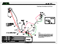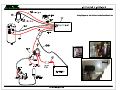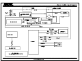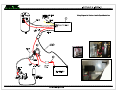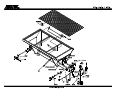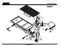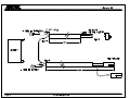
1
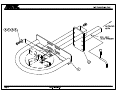
AG6E/AG8E/AG10E
Owners Manual
Electric Salt & Sand Spreader
Models AG6E/AG8E/AG10E
Warning:
Do not exceed GVWR or GAWR with spreader and load. Overloading could result in an
accident or damage.
Read this manual before installing or operating the spreader.
Page 1
www.arcticsnowplows.com
AG6E/AG8E/AG10E
Sander Warranty
ARCTIC salt/sanding equipment is guaranteed to be free from defects in material or
workmanship under normal use and service for 1 (one) year after the date of purchase.
Arctic Equipment Manufacturing Corporation will replace or repair, at its election,
without charge, any part which becomes defective within the period of time described
above.
See specifications below what is not covered under warranty.
In no event shall Arctic Equipment Manufacturing Corporation be liable for claims for
loss of use or consequential damages.
This warranty is made only to the original purchaser. There is no other warranty
expressed, implied, or statutory.
All parts returned to us, transportation charges prepaid, must be accompanied with a
"Return Goods Authorization" number, obtained from the factory. In order to reduce
down-time, we will, on your request, send the parts required and you will be billed under
the usual terms. A credit will be issued to your account when the parts, in our
examination, prove to be defective.
Arctic Equipment Manufacturing Corporation reserves the right to change specification
without prior notice.
Specifics not considered under warranty
Certain types of damage can occur, which cannot be attributed to defects in material
and/or warranty, but rather as the owner's responsibility.
These conditions include, but are not limited to the following items. Damage resulting
from:
1. Lack of or dirty lubrication.
2. Using other than recommended grade and type of lubrication.
3. Accident, abuse or neglect.
4. Stripped keyways or splines on external shafts.
5. Running over recommended speeds.
6. Repairs by an unauthorized person.
7. Damage caused by improper mounting or conditions on units not mounted by factory.
8. Improper maintenance or storage of equipment.
Customer Responsibility
The loaded vehicle, including all after market accessories, the salt/sanding equipment,
passengers, and cargo, MUST NOT exceed the gross vehicle weight ratings (GVWR),
front gross axle weight rating (FGAWR) or rear gross axle weight rating (RGAWR)
Page 2
www.arcticsnowplows.com
AG6E/AG8E/AG10E
specified on the Safety Compliance Certification Label located in the driver’s side door
opening. It is the operator’s responsibility to verify that these ratings are not
exceeded.
To determine the Gross Axle Weights for your vehicle, including all after market
accessories, the salt/sanding equipment, passengers, and cargo, take your loaded vehicle
to a scale. Place the front wheels of the vehicle on the scale to get the Front Gross Axle
Weights (FGAW). To get the Rear Gross Axle Weights (RGAW), place the back wheels
of the vehicle on the scale.
Disclaimer notice
Arctic Equipment Manufacturing Corporation (Arctic) does not assume liability for
damage to your motor vehicle resulting from the attachment or use of Arctic salt/sanding
equipment. The purchaser assumes all vehicle risk associated with the attachment and
operation of this salt/sanding equipment.
The added weight may impair the operation and control of your vehicle. Additional
equipment may be necessary before installing salt/sanding equipment. Please consult
your vehicle dealers prior to the purchase and installation of the salt/sanding equipment.
Page 3
www.arcticsnowplows.com
AG6E/AG8E/AG10E
Safety and warnings
WARNING:
- Do not exceed the gross vehicle weight ratings (GVWR), front gross axle
weight rating (FGAWR) or rear gross axle weight rating (RGAWR) with spreader
and load. Overloading could result in an accident or damage.(Refer to Material
Density chart below)
Material Density
(lb per cubic yd)
Fine Salt – Dry 1400
Coarse Salt – Dry 1300
Coarse Sand – Dry 2800
Coarse Sand – Wet 3300
For Electric sander with the variable speed box:
-Never hook booster cables directly to the motor; this would void your warranty.
-Unplug sander battery cables before boosting your truck.
Before attempting any procedure in this book, read and understand all the safety
information contained in this section. In addition, ensure all individuals working with you
are also familiar with these safety precautions.
For your safety, warning and information decals have been placed on this product to
remind the operator to take safety precautions. It is important that these decals are in
place and are legible before operation begins. New decals can be obtained from Arctic
Equipment Manufacturing or your local dealer.
Remember it is the owner’s responsibility for communicating information on the safe use
and proper maintenance of this equipment. The careful operator is the best operator.
Most accidents are caused by human error. Certain precautions must be observed to
prevent the possibility of injury to operator or bystanders and/or damage to equipment.
- Driver to keep bystanders a minimum of 25 feet away from operating spreader.
-Servicing the sander without special tools and knowledge could result in personal injury.
See an authorized Arctic dealer for service.
- Before servicing the spreader, wait for conveyor or spinner to stop and then lock out
power.
- Do not climb into or ride on spreader.
- Disconnect electric and/or hydraulic power and tag out if required before servicing or
performing maintenance.
Page 4
www.arcticsnowplows.com
AG6E/AG8E/AG10E
-Do not allow hands, hair or clothing to get near any moving parts such as spinner, chain
etc.
-Do not wear neckties or loose clothing when working on the vehicle. These things can
catch on moving parts or cause an electrical short circuit that could result in personal
injury. Do not wear wrist watches, rings or other jewellery when working on the vehicle
or individual equipment
-Do not allow unauthorized person to operate this unit.
-Do not work on a vehicle without having a fully serviced fire extinguisher available.
(Dry chemical unit specified for gasoline, chemical or electrical fires).
-Do not smoke while working on the vehicle. Gasoline and battery acid vapours are
extremely flammable and explosive.
-Do not alter the sander, or any part without written approval of Arctic Equipment
Manufacturing Corporation.
-Do not use your hands to search for hydraulic fluid leaks; escaping fluid under pressure
can be invisible and can penetrate the skin and cause injury.
- Do not leave unused material in hopper. Material can freeze or solidify, causing
unit to not work properly. Empty and clean after each use.
-Inspect the sander periodically for defects. Parts that are loose, broken, missing or
plainly worn must be tightened or replaced immediately.
-Check the job site for terrain hazards, obstructions and people. Check surrounding area
for hazardous obstacles before operating this unit.
-Wear safety goggles when working on the vehicle to protect your eyes from battery acid,
gasoline, and dust or dirt from flying off of moving engine parts.
-Be aware of and avoid contact with hot surfaces such as engine, radiator, and hoses.
-Wear safety glasses with side shields when striking metal against metal. Failure to heed
could result in injury to the eye(s) or other parts of the body.
-Shut off the vehicle engine, place the transmission in neutral or park, turn the ignition
switch to the “off” position, firmly apply the parking brake of the vehicle before
removing / installing the sander.
Page 5
www.arcticsnowplows.com
AG6E/AG8E/AG10E
- Be sure that the sander is properly attached before moving the vehicle.
-To remove the sander, the unit must be empty. Do not stand close to the sander when it
is being lifted. Keep a safe distance away.
Sander Specification
-
3/4HP electric motor, 55 amp electric motor
-
In cab variable speed controller or On/Off toggle switch
Variable Speed Controller for Electric Spreader is used for precise spreading. See
more information in Variable Speed Control Section.
ON/ OFF switch - When a switch handle is in OFF position, a switch handle is not
illuminated. If spreader in ON (motor is on) switch handle is illuminated red. If
switch handle is illuminated white in OFF position a solenoid (under hood) is stuck
and motor is running constantly. Disconnect power by removing connectors that
connect two red and black cables at the back of the truck. See authorized Arctic
Dealer.
-
The motor and drive system is protected by a hinged hood
-
Quiet electric-drive system
-
Low-maintenance
-
Stainless steel drive chain and hardened sprockets
Electric sander is equipped with an adjustable sand discharge chute. You can vary the
spread width by simply redirecting the sand to another part of the spinner.
Page 6
www.arcticsnowplows.com
AG6E/AG8E/AG10E
Spreader Installation
The AG6E spreader is designed for installation in a 6'/8' pickup truck bed. The AG8E is
designed for installation in an 8’ pickup truck bed. The AG10E spreader is designed for
10' dump truck or flat deck truck. Follow the steps below to install your unit in your
vehicle.
a) Slide spreader into position and secure with the ratchet straps into the cargo tie downs
of the truck (pictures # 3 and #4)
b) Bolt mounting angle bracket to spreader, then bolt it to the back of the truck using ½"
bolt. (Picture #2)
c) Install the sand chute using the required pivoting/fastening components. (Picture #12)
d) Assemble the spinner assembly (split shafts), as shown in the assembly drawing in this
manual, using the appropriate components. (Picture #5, 11 and 12)
e) You may change the spinner disc height. Using the hole in the spinner disc hub as a
guide, drill a hole through the shaft, for the mounting bolt. Cut off any excess length
from the shaft and install the spinner disc.
f) Connect all the cables as shown in the electric system diagram. Be sure to grease all
connections.
Maintenance
Daily Inspection and Lubrication
a)
Check gearbox oil level. It should be filled to the oil level plug. (Picture#1)
b)
Lubricate the following grease nipples:
1) 1 on conveyor idler shaft bearing (2 bearings) (picture #8)
2) 1 on drive shaft bearing (picture #7)
3) 1 on spinner shaft bearing (2 bearings if one hydraulic motor is used, 1 bearing
if two hydraulic motors are used) (Picture #11)
4) 1 on each coupling split shaft and gear box coupling (pictures #5 and #6)
Yearly Inspection
a)
Page 7
At the end of the operating season, the unit should be thoroughly cleaned and
lubricated. The conveyor chain (picture #9) should, ideally, be stored in oil. These
www.arcticsnowplows.com
b)
AG6E/AG8E/AG10E
preventative measures should prevent premature rusting of the unit. Grease bolts
on the chain tighteners. (Picture #8)
At this time or before the start of the next season, it is wise to check all drive
components for appreciable wear. Any components which are questionable should
be replaced now. This short and simple check will avoid down time during the
operating season.
c)
Change the gear box oil.
e)
Replace the oil filter. (Note: If the unit is utilized year round, replace it twice a
year).
Before Operating
a)
b)
Grease all lubrication points.
Ensure that the conveyor chain is dragging for one foot on the bottom return
channel, of the spreader. (Do not over tighten the chain).
Lubricants
Speed Reducer Lubricant……………80W90 Gear lube
Page 8
www.arcticsnowplows.com
AG6E/AG8E/AG10E
Picture #1
Picture #2
Picture #3
Picture #4
Picture #5
Page 9
Picture #6
www.arcticsnowplows.com
AG6E/AG8E/AG10E
Picture #7
Picture #8
Picture #9
Picture #10
Picture #11
Page 10
Picture #12
www.arcticsnowplows.com
AG6E/AG8E/AG10E
Troubleshooting of the Wireless Controller
It is important to know that the in-cab remote control and the controller on the spreader
communicate with RF signals. Therefore, they are in constant communication with one another.
This type of communication allows you to get instant info on your setting and it will also inform
you on any problems that could happen during the use of your spreader.
Never hook booster cables directly to the motor; this would void your warranty.
Unplug sander battery cables before boosting your truck.
Problems:
-
When the screen on the remote shows ‘’O’’ it means that the system is in OVERLOAD
An overload of the system can caused by:
•Frozen material inside the hopper.
•Accumulation of material in front and under the spreader
•Bearing starting to seize
•Worn-out conveyor chain
•Accumulation of material between the floor of the spreader and the drive sprockets.
•Battery in bad condition
•Controller poorly installed
-
When the ‘’O’’ is constantly rotating, this means, there is no communication (loss of
signal) between the remote control and the control box. The spreader will automatically
shut off.
By turning the main switch off and then turning it back on, the signal should come back.
If the signal doesn’t come back you can connect the remote directly to the black box by
using the appropriate connectors on the controller. This operation will reset the system.
If the problem persists here are some possibilities:
•Power is not going to the controller (black box)
•Check fuses ( 5 amp and 80 amp)/ Breaker engaged (if applicable)
•Bad connections
•Electrical noises or interferences
•Poorly installed controller
Page 11
www.arcticsnowplows.com
1
2
3
4
5
6
7
8
9
10
11
12
13
14
15
16
17
18
19
20
21
22
23
24
25
26
27
28
28a
29
30
31
32
33
AG6E/AG8E/AG10E
EQVSC-6/8-D & EQVSC-10-D Variable Speed Dual Electric Control Kit
Part #
Description
Quantity
90305-M
Dual Variable Speed Kit (include box and controller)
1
HH-00340-002
7/16-14 Lock nut
4
HH-00293-072
7/16-14 x 1.3/4 HHCS
4
HH-00020-081
1/8” x ¾” Cotter Pin
1
90040-N
Sander Ratchet Strap
4
HH-00293-028
5/16-18x1 HHCS
3
HH-00341-003
5/16 Flatwasher
3
HH-00340-017
5/16-18 Lock nut
3
HH-01081-054
3/8-16 x 2.1/2 Grade
2
HH-00340-001
3/8-16 Lock Nut
2
HH-00789-003-14 3/16 14" Chain
1
90303-B
Battery Cable with 80 amp fuse
1
HH-00972-090
1/2-20x1.1/2 HHCS
4
HH-00540-004
1/2-20 Lock Nut
4
HH-00455-007
#8x3/4 screw
2
90190-N
Solenoid
1
90306-B
Spinner Shaft (dual motor only)
1
HH-00013-073
#8-32x5/8 screw
4
HH-00340-019
#8-32 Hug Locknut
4
90307-N
Gear Motor
1
HH-00905-013
Spinner Bearing
2
HH-00017-024
1/4-20x1/4 set screw
2
90229-N
Salter Plate Light
1
53207-N
License Plate Plastic Nut
2
761232
Butt Connector
1
768222-048
Brown Wire 48”, 14 g
1
769977-03
1/4" x 3" Shrink Tube
1
90030-VSC
Power Cable, Cab Section (for EQVSC-10-D only)
1
90030-VSC-6/8
Power Cable, Cab Section (for EQVSC-6/8-D only)
1
HH-00909-003
M6x20mm hex bolt
4
HH-00932-001
M6 Flat Washer
4
HH-00933-001
M6 Lock Washer
4
90308-A
4” Ground Wire
1
HH-00455-007
#8 Self tapping Screw
2
Page 12
www.arcticsnowplows.com
1
2
3
4
5
6
7
8
9
10
10a
11
12
13
14
15
16
17
18
19
20
21
22
32
33
AG6E/AG8E/AG10E
EQVSC-6/8 & EQVSC-10 Variable Speed Electric Control Kit
Part #
Description
90304-M
Variable Speed Control Kit (include box and controller)
HH-00020-081
1/8” x ¾” Cotter Pin
90040-N
Sander Ratchet Strap
HH-00293-028
5/16-18 x 1 HHCS
HH-00341-003
5/16 Flatwasher
HH-00340-017
5/16-18 Lock nut
HH-01081-054
3/8-16 x 2.1/2 Grade
HH-00340-001
3/8-16 Lock nut
HH-00789-003-14
3/16 14" Chain
90030-VSC
Power Cable, Cab Section (for EQVSC-10-D only)
90030-VSC-6/8
Power Cable, Cab Section (for EQVSC-6/8-D only)
HH-00972-090
1/2-20 x 1.1/2 HHCS
HH-00540-004
1/2-20 Lock nut
HH-00455-007
#8x3/4 Screw
90303-B
Battery Cable with 80 amp fuse
HH-00013-073
#8-32 x 5/8” Screw
HH-00340-019
#8-32 Lock nut
90190-N
Solenoid continues Duty
90229-N
Light
53207-N
License Plate Plastic Nut
761232-M
Butt Connector
768222-048
Brown Wire 48” 14ga
769977-03
1/4" x 3" shrink tube
90308-A
4” Ground Wire
HH-00455-007
#8 Self tapping Screw
Page 13
www.arcticsnowplows.com
Quantity
1
1
4
3
3
3
2
2
1
1
1
4
4
2
1
4
4
1
1
2
1
1
1
1
2
1
2
3
4
5
6
7
8
9
10
11
12
13
14
15
15a
15b
16
17
18
19
20
21
22
23
24
25
26
27
28
29
30
30a
30b
31
31a
32
32a
32b
Page 14
AG6E/AG8E/AG10E
Galvanized Sander AG6, AG8, AG10 With Electric Motor
Part #
Description
90151-N
Electric Motor ¾” HP
90117-C
Mounting Plate
90118-A
Top Bearing Plate
90161-B
Platform for Electric Motor
90090-N
Gearbox Pulley, 2.3"
90162-B
Top Spinner Shaft
90152-N
Sprocket motor side, 2”
90153-N
Sprocket gear box side, 6”
RB-32992-05
Chain Connecting Pin
90150-N
Gear Box 50:1
RB-32992-04
Chain Connecting Link
HH-00905-013
Spinner Bearing
RB-889-G
Spinner Disc
RB-32996
Chute
90093-D-E
Sander, 6', body weldment
90094-D-E
Sander, 8', body weldment
90095-D-E
Sander, 10', body weldment
90119-B
Drive Coupling
RC-32854-02-GA
Hinge Pin for sander chute
HH-00020-081
Cotter Pin, 1/8" dia x 3/4" lg
HH-00859-019
Drive Shaft Bearing, Four Bolt Flange
RB-872
Drive Sprocket
HH-00291-101
Key, 1/4" Square x 2 -3/4"
90120-B
Drive Shaft
HH-00789-003-14
Chain , 3/16" dia x 14" long
HH-00789-003-20
Chain , 3/16" dia x 20" long
90128-D
Hood
90131-A
Bolt for idler bearing (chain tightener )
HH-00859-014
Idler Shaft Bearing, Four Bolt Flange
RB-874
Idler Sprocket
RB-876
Idler Shaft
RB-32992
Chain, AG6 only
RB-32992-02-E
Chain, AG8 only
RB-32992-03-E
Chain, AG10 only
90114-96-C
V Channel, AG8
90114-120-C
V Channel, AG10
90133-N
Screen AG6
90134-N
Screen AG 8
90135-N
Screen AG10
www.arcticsnowplows.com
Quantity
1
1
1
1
2
1
1
1
1
1
1
2
1
1
1
1
1
1
1
1
1
2
2
1
1
2
1
2
2
2
1
1
1
1
1
1
1
1
1
33
34
34a
34b
35
36
37
38
39
40
41
42
43
44
45
46
47
48
49
50
51
52
53
54
55
56
57
58
59
60
61
62
63
64
65
66
67
68
69
Page 15
AG6E/AG8E/AG10E
Galvanized Sander AG6, AG8, AG10 With Electric Motor
Part #
Description
90252-N
Rubber Grip for Gate Handle
HH-00857-006
Hood Latch
HH-00013-074
#8 x 3/4” Screw
HH-00340-019
#8 Lock nut
90182-M
Electric Motor drive chain (35”)
90148-N
Belt, Gearbox to Spinner Shaft, A31
HH-00960-009
Bearing (to support gear box input shaft)
90168-A
Replaceable Spinner Disc Fin – part of RB-889
HH-00291-011
Gearbox input shaft Key 1/4" Square x 3.5"
HH-00291-102
Motor Sprocket Key 1/4"Square x 1.50"
90040-N
Strap
90124-B
Gate Guide, top plate
90123-B
Gate Guide, bottom plate
90126-B
Gate Arm
90125-A
Gate Middle Link
90122-A
Gate
HH-00972-092
½”-20 UNF x 2” HHCS
HH-00293-003
¼” -20 UNC x 5/8” HHCS
HH-00293-028
5/16"-18 UNC x 1" HHCS
HH-00293-029
5/16" -18 UNC x 1 1/4" HHCS
HH-00293-049
3/8”-16 UNC x 1” HHCS
HH-00293-055
3/8" -16 UNC x 2 1/2" HHCS
HH-00293-069
7/16"-14 UNC x 1" HHCS
HH-00293-072
7/16" -14 UNC x 1 3/4" HHCS
HH-00293-088
½”- 13 UNC x 1” HHCS
HH-00294-007
5/8" -11 UNC Nut
HH-00340-001
3/8"-16 UNC Lock Nut
HH-00340-002
7/16"-14 UNC Lock Nut
HH-00340-003
1/2"-13 UNC Lock Nut
HH-00340-017
5/16” – 18 UNC Lock Nut
HH-00340-901
1/4” – 20 UNC Lock Nut
HH-00341-003
5/16" Flat Washer
HH-00341-005
7/16” Flat Washer
HH-00341-006
½” Flat Washer
HH-00457-001
½” Lock Washer
HH-00457-004
3/8” Lock Washer
HH-00460-002
½” – 20 UNF Nut
HH-00540-004
½” – 20 UNF Lock Nut
HH-00971-043
5/16" -18 UNC x 1" Carriage Bolt
www.arcticsnowplows.com
Quantity
2
4
4
1
1
1
1
1
1
4
2
2
1
1
1
1
8
5
6
4
2
4
4
6
4
2
24
1
15
8
18
8
9
4
8
2
3
2
70
71
72
73
74
75
76
77
78
79
79a
80
81
82
83
84
85
86
87
88
89
90
91
92
93
94
95
96
97
98
99
AG6E/AG8E/AG10E
Galvanized Sander AG6, AG8, AG10 With Electric Motor
Part #
Description
HH-00971-044
5/16" -18 UNC x 1.25" Carriage Bolt
HH-00971-104
7/16" -14 UNC x 1" Carriage Bolt
HH-00971-106
7/16" -14 UNC x 1.5" Carriage Bolt
HH-00972-090
½” -20 UNF x 1.5” HHCS
HH-00972-091
½” -20 UNF x 1.75” HHCS
HH-00294-002
5/16”-18 Hex Nut
HH-01149-008
5/16”-18 x 3.75” Eyebolt
RB-38759
Mounting Stop Angle (Not Shown)
90154-A
Plate, Poly, Screen Hold Down
90165-B
Bottom Split Spinner Shaft
90167-B
Bottom Split Spinner Shaft Extended
90162-B
Top Spinner Split Shaft
HH-00233-001
¼”-28 Grease fitting
HH-01081-054
3/8 16x 2 ½ Grade 8 bolt
HH-00291-101
Spinner Shaft Pulley Key 1/4" Square x 2.75"
90115-03-B
Plate, Sand Guide
HH-01081-054
3/8-16 x 2.5 grade 8
HH-00340-001
3/8 -16 Nut with Nylon Insert
HH-00293-028
5/16” -18 UNC x 1”
HH-00341-003
5/16” Flat washer
HH-00340-017
5/16” -18 UNC Hex locknut
HH-00972-090
½”-20 UNF x1.5” HHCS
HH-00540-004
½”-20 UNF Lock Nut
90307-N
Gear Motor (dual motor only)
90306-B
Spinner Shaft (dual motor only)
HH-00909-003
M6x20mm hex bolt (dual motor only)
HH-00932-001
M6 Flat Washer (dual motor only)
HH-00933-001
M6 Lock Washer (dual motor only)
HH-00294-003
3/8” Nut
HH--00293-049
3/8” x 1” Bolt
HH-00017-024
1/4-20x1/4 set screw (dual motor only)
Quantity
2
4
12
1
1
2
1
1
1
1
1
1
5
2
1
2
2
2
1
1
1
4
4
1
1
4
4
4
4
4
2
Arctic Equipment Manufacturing Corporation reserves the right under its product improvement policy to change construction or
design details and furnish equipment when so altered without reference to illustrations or specifications used.
Page 16
www.arcticsnowplows.com
Vibrator Kit
Part # 90290-80-M & 90291-200-M
Page 1
www.arcticsnowplows.com
Vibrator Kit
Vibrator Kit
Vibrator kit for a hitch mount poly salter 90290-80-M
Part #
Description
90290-80-N
Vibrator
90292-B
Harness
90004-M
On/Off Switch
90257-A
Support Plate
HH-00300-051 3/8” x 1 ½ Hex Head Screw Stainless Steel
90293-N
3/8” Flat Washer Stainless Steel
HH-00086-001 3/8” Nut with Nylon Insert Stainless Steel
52018-M
Bracket
1
2
3
4
5
6
7
8
Quantity
1
1
1
1
4
4
4
1
Installation Instructions for hitch mount poly salter:
1. Locate the vibrator (1) as shown on the picture below, approximately 7” (+/- 1”) from the
line off the throat entry.
2. Mark the mounting holes on the hopper and drill 7/16” holes through.
3. Install the support plate (4) from the inside of hopper and secure it using 3/8bolt, flat
washer and nut (5)(6)(7).
4. Disconnect vehicle electrical system from the battery. Install the harness, the switch
(switch mounting bracket) as shown on the attached diagram.
Page 2
www.arcticsnowplows.com
Vibrator Kit
Vibrator kit for a galvanized and a poly sander 90291-200-M
Part #
Description
90291-200-N
Vibrator
90292-B
Harness
90004-M
On/Off Switch
90257-A
Support Plate
HH-00300-051 3/8” x 1 ½ Hex Head Screw Stainless Steel
90293-N
3/8” Flat Washer Stainless Steel
HH-00086-001 3/8” Nut with Nylon Insert Stainless Steel
52018-M
Bracket
1
2
3
4
5
6
7
8
Quantity
1
1
1
1
4
4
4
1
Installation Instructions for the galvanized and the poly sander:
1. Locate the vibrator (1) as shown on the picture below.
2. Mark the mounting holes on the hopper and drill 7/16” holes through.
3. Install the support plate (4) from the inside of poly hopper (it is not necessary to install
that plate for the galvanized sander) and secure it using 3/8bolt, 3/8 flat washer and 3/8
nut (5)(6)(7).
Disconnect vehicle electrical system from the battery. Install the harness, the switch (switch
mounting bracket) as shown on the attached diagram.
Warning: Vibration is a destructive force and it may damage sander and hopper body. You may
use this vibrator at your own risk. In no event shall Arctic Equipment Manufacturing
Corporation be liable for claims for loss of use or consequential damages.
Arctic Equipment Manufacturing Corporation reserves the right under its product improvement policy to change construction or
design details and furnish equipment when so altered without reference to illustrations or specifications used.
Page 3
www.arcticsnowplows.com
Hitch Mounted Spinner Guard
Part # 90175-M
Page 1
www.arcticsnowplows.com
Spinner Guard
Spinner Guard
Spinner Guard
Description
Hoop Weldment
Receiver weldment, spinner guard
½” Flatwasher
½” Lockwasher
½” – 20 Hex nut
½”-20, 1 ½ Bolt
5/8”, 2 ½” long hitch pin assembly
Quantity
1
1
4
4
4
4
1
Item
1
2
3
4
5
6
7
Part #
90176-B
90179-B
HH-00341-006
HH-00457-001
HH-00460-002
HH-00972-090
51830-B
Mounting Instructions:
1: With sander installed and securely in place, insert Receiver weldment (2) into vehicle hitch.
2: Using provided hardware, attach the Hoop weldment (1) to Receiver weldment (2) in a
position that best protects the spinner disc from impact and does not impede the spreading of
sand/salt. Hoop should function best if it is located approx. 1” below the bottom of the spinner
disc.
3: Once the proper location is determined, the hitch pin (7) hole (21/32” dia.) should be drilled in
the receiver weldment (tube) (2) (Use the vehicle hitch pin hole as a guide).
4: After all parts are installed and tightened, ensure the hitch pin (7) is inserted and secured
properly.
Warning:
-Spinner guard is not a substitute for good driving practices. Always drive with care and be
aware of your surroundings (obstructions).
-Spinner guard should only be used for original manufacturer’s application.
-Do not use as a step
-Do not alter or modify spinner guard
-Do not tow with spinner guard in place.
-Remove spinner guard when sander is not in truck
Arctic Equipment Manufacturing Corporation reserves the right under its product improvement policy to change construction or
design details and furnish equipment when so altered without reference to illustrations or specifications used.
Page 2
www.arcticsnowplows.com