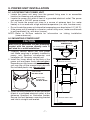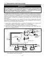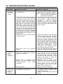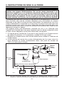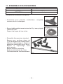
1
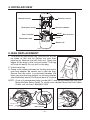
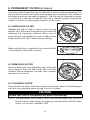
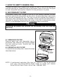
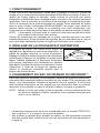
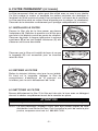
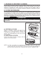
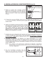
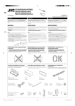
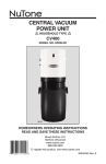
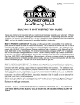
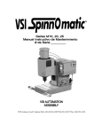
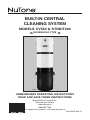
BUILT-IN CENTRAL
CLEANING SYSTEM
MODELS CV654 & STDKIT200
! HOUSEHOLD TYPE !
AB0018
HOMEOWNERS OPERATING INSTRUCTIONS
READ AND SAVE THESE INSTRUCTIONS
Broan-NuTone Canada Inc.;
Mississauga, Ontario
www.nutone.ca
888-882-7626
To register this product, visit www.nutone.ca
30042402 Rev. A
IMPORTANT SAFETY INSTRUCTIONS
READ ALL INSTRUCTIONS BEFORE USING THIS APPLIANCE.
When using an electric appliance, basic precautions should always be followed,
including the following:
WARNING
!
TO REDUCE THE RISK OF FIRE, ELECTRIC SHOCK, OR PERSONAL INJURY:
• Do not use on wet surfaces or outdoors.
• Do not allow to be used as a toy. Close attention is necessary when used by or
near children.
• Use only as described in this manual. Use only manufacturer's recommended
attachments.
• Do not put any object into openings. Do not use with any opening blocked; keep
free of dust, lint, hair, and anything that may reduce air flow.
• Keep hair, loose clothing, fingers and all parts of body away from openings and
moving parts.
• Do not pick up anything that is burning or smoking, such as cigarettes, matches,
or hot ashes.
• Do not use without dustbag or filter in place.
• Do not use to blow leaves or debris.
• Do not vacuum liquids or fine powders (such as drywall dust).
• Do not put any object on the unit.
• Ensure air flows freely to both side intake vents and exhausts unobstructed
from top outlet.
• Do not install the unit horizontally.
• Do not use the pail as a wash pail.
• Do not use the pail as a stool.
• Turn off all controls before unplugging.
• Use extra care when cleaning on stairs.
• Avoid picking up sharp objects.
• Do not use to pick up flammable or combustible liquids such as gasoline or use
in areas where they may be present.
• Do not use with damaged cord or plug. If appliance is not working as it should,
if it has been dropped, damaged, left outdoors, or dropped into water, return it
to a service center.
• Do not unplug the unit by pulling on cord. To unplug, grasp the plug, not the cord.
• Do not handle plug or appliance with wet hands.
• Connect to a properly grounded outlet only. See grounding instructions on
page 8.
• Any servicing other than that recommended in this manual should be
performed by an authorized service facility.
• We recommend that your unit be inspected by a specialized technician once a
year.
SAVE THESE INSTRUCTIONS
-2-
1. OPERATION
The power unit is located away from the everyday living areas of your home — usually
in the garage, basement, or utility room. Through a network of strong, lightweight
tubing, the power unit connects to inlets strategically placed throughout your
home. When you are ready to clean, attach the wand and cleaning tool onto the
end of the hose. Open the inlet cover and insert the end of the hose into the inlet.
Use the ON/OFF switch on the hose handle* to activate the power unit. As you
vacuum, dirt and dust are transported to the power unit where they remain in a
bag or in the debris pail.
NOTE: The rocker switch on the front of the power unit can be used to turn the
power unit on.
Use the cleaning tools as you would for any other vacuum cleaner. Avoid picking
up pine needles, coffee sticks and other similar objects. These kinds of objects
may become lodged in the hose or tubing.
2. VACUUM POWER CONTROL
The hose handle* is equipped with a control ring to
regulate the air flow. The control ring covers a “bleeder”
hole. Open the hole to reduce the suction for cleaning
draperies, small rugs, and other light fabrics. Some
very thick, plush carpets with high density yarns also
require reduced suction to make the nozzle easier to
push. Be sure to close the control ring completely
over the hole to produce the maximum power required
for most other cleaning tasks.
AA0009
CONTROL
RING
3. WHEN TO CHANGE BAG OR EMPTY DEBRIS PAIL**
With a 6 U.S. Gallons capacity, under normal conditions the bag/debris pail
requires changing/emptying approximately twice a year. If the bag/debris pail is
filled, you will notice a complete loss of vacuum in the system. Unless this loss of
vacuum is caused by a blockage in the system, changing the bag or emptying the
debris pail will solve the problem.
NOTE: Even if not filled to capacity, if the bag seems tightly stretched when
removing the debris pail, changing the bag will prevent it from tearing.
* The accessory kit is included only with the STDKIT200 model. See section 11
on page 10 for more details.
** In order to use the debris pail to collect debris, the optional permanent filter has
to be installed in the power unit (see permanent filter instructions on page 5).
-3-
4. DETAILED VIEW
ROCKER
EXHAUST
SWITCH
SECONDARY
INLET
FILTER
VACUUM
DISPOSABLE
CHAMBER
INLET
CHAMBER
OUTLET
BAG
ADAPTER
LATCH
BAG
DEBRIS
PAIL
AL0003
5. BAG REPLACEMENT
1. To remove the disposable bag, release both latches
on sides of the unit by pulling out and then
pushing up. Remove the pail from unit. Grasp the
edges of the bags’ collar and pull down. The bag
will slide off easily. Do not pull on the bag.
2. Unfold new bag.
3. Grasp collar where indicated on the bag and insert
over bag adapter. Be careful not to tear the bag.
Ensure that the collar is positioned between the
taper ring and the bag stopper on the bag adapter
(see illustration below). Put the pail back in its place
AA0004
NOTE : A set of 3 replacement bags (model 391C) may be purchased from you local
Broan-NuTone Sales Outlet. To locate your nearest Broan-NuTone Sales
Outlet, call toll free 1-888-882-7626.
TAPER
AO0024
RING
BAG
STOPPER
-4-
AO0025
6. PERMANENT FILTER (OPTIONAL)
The optional permanent filter can be used with or without the disposable bag. This
filter protects the motor and stops small particles from escaping to the outside of
the power unit wihout the need to replace it. The filter can be removed by means
of a pull-tab for cleaning (if need be). Be sure to reinstall properly. Appropriate
location is critical to insure proper protection of the motor.
6.1 INSTALLING FILTER
Squeeze the filter in order to place it over the bag
adapter (A). Let the filter prop against the unit wall by
releasing the squeezing pressure. Make sure to
place the rigid ring between the upper rib (B) and the
three bottom posts (C) to ensure proper sealing.
A
B
C
AO0028
Make sure the filter is installed so that the pull tab (D)
is accessible for future filter removal.
D
AA0005
6.2 REMOVING FILTER
Remove debris pail and disposable bag. Using pull
tab on edge of filter, pull and loosen filter from inlet
chamber wall by squeezing it on itself. Then, carefully
remove it from the unit.
AO0027
6.3 CLEANING FILTER
Simply brush filter clean. If the filter is excessively soiled, wash in a mild detergent
and let it dry completely before putting it back in its place.
CAUTION
Ensure that filter is completely dry before reinstalling.
NOTE: The permanent filter (model PF450) may be purchased from you local
Broan-NuTone Sales Outlet. To locate your nearest Broan-NuTone Sales
Outlet, call toll free 1-888-882-7626.
-5-
7. HOW TO EMPTY DEBRIS PAIL
To empty the debris pail, release both latches on sides of the unit by pulling out
and then pushing up. Holding the pail by the latches, lower it from unit. Carry pail
to trash receptacle and dispose of debris. Put the pail back in its place.
8. SECONDARY FILTER
A secondary safety filter, located at the top of the vacuum chamber provides
protection against dirt being pulled into the motor if the disposable bag or permanent
filter should accidentally be torn. This filter should be checked and cleaned if
necessary, when replacement bag is installed or when optional permanent filter is
removed for cleaning. Simply brush filter clean. If the filter is excessively soiled,
wash in a mild detergent and let it dry completely before reinstalling.
CAUTION
Operating the power unit without the secondary filter will void the
warranty.
8.1 REMOVING FILTER
Remove debris pail and disposable bag or
permanent filter. Remove both locking sleeves
from the retaining hooks. Carefully pull filter
down to remove.
RETAINING
HOOKS
8.2 REINSTALLING FILTER
To reinstall the secondary filter, reverse the steps
described above.
SECONDARY
FILTER
LOCKING
SLEEVES
AO0029
NOTE: A replacement secondary filter (part no. 10941310) may be purchased
from your local Broan-NuTone Sales Outlet. To locate your nearest
Broan-NuTone Sales Outlet, call toll free 1-888-882-7626.
-6-
9. POWER UNIT INSTALLATION
9.1 LOCATING THE POWER UNIT
• Locate the power unit away from the general living area in an accessible
location for cleaning and maintenance.
• Locate the power unit within 6 feet of a grounded electrical outlet. The power
unit requires a 120 VAC power source.
• Do not locate the power unit close to a source of extreme heat (i.e.: water
heater) or in an area with a high ambient temperature (i.e.: attic, furnace room).
• Do not locate the power unit where the temperature can drop below 0°C (32°F).
• If the power unit is located in a closet or a small utility room, make sure the area
is well-ventilated (i.e.: with door louvers).
NOTE: Refer to NuTone website for information on tubing installation
(www.nutone.ca).
9.2 MOUNTING POWER UNIT
CAUTION
Make sure to assemble the wall mounting
bracket with the screws directly onto a
wall stud for a solid installation.
MINIMUM WALL CLEARANCE
DIMENSIONS
14" MIN.
PVC TUBING STRAP
INLET
INLET
EXHAUST
1. Carefully remove debris pail from power
unit. Make sure bag is properly installed in
power unit. Remove accessories and
installation kit. Securely reinstall pail.
2. Install the 3-way elbow on the back of the
power unit and press firmly (do not glue).
Depending on the house vacuum line setup,
you may cap off the unused inlet tube with
the included plastic cap (do not glue).
TOP VIEW
CEILING
12" MINIMUM TO CEILING
WALL BRACKET
EXHAUST
3-WAY ELBOW
DO NOT GLUE
22"
PLASTIC CAP
(IF NEED BE)
DO NOT GLUE
41"
INLET
INLET
60"
AO0030
3. Install mounting bracket on a wall stud within
6 feet of a grounded electrical outlet, at the
distances specified on illustration beside.
Ensure that wall between mounting bracket
and inlet is straight and leveled.
FRONT VIEW
18" MINIMUM ABOVE FLOOR
FLOOR
AD0040A
-7-
9. POWER UNIT INSTALLATION (CONT’D)
RETAINING SCREW
LOCATIONS
4. Use the mounting bracket as a template to
mark the position of its screws. Drill the
upper and lower screw holes into the stud
using a 3/16” drill bit.
MOUNTING BRACKET
CENTER OPENING
AA0006
5. Using a Phillips screwdriver, secure the mounting bracket to the wall with
2 no. 14 x 2” screws (included). Make sure that the bracket is tight against the
wall.
6. Hang the power unit by inserting its back hook
into the center opening of its mounting bracket.
Make sure hook is securely engaged in bracket.
Secure the power unit to the mounting bracket,
with the provided no. 6 x 3/8” screw and washer
into the small remaining hole using a Phillips
screwdriver (see illustrations beside).
WASHER/SCREW
LOCATION
WASHER/SCREW
INSTALLED
TOP
TOP
AD0041
AD0042
OF THE
UNIT
OF THE
UNIT
7. Run house vacuum line up to the 3-way elbow behind the power unit. Secure
house vacuum line to the appropriate 3-way elbow opening with PVC glue (do
not glue the 3-way elbow to the power unit).
8. Connect muffler (if desired) and exhaust tubing to exhaust outlet on top of the
power unit. The exhaust should not be vented into a wall, ceiling or concealed
space in the house. Exterior vented exhaust lines should end using model V142
wall cap.
NOTE: Exhausting the power unit to the outside is recommended for optimal
performance but is not required.
9. Once everything is in place, secure the
piping (near the elbow) to the wall using the
included PVC strap.
AO0031
-8-
PVC
STRAP
10. GROUNDING INSTRUCTIONS
! WARNING
Improper connection of the equipment-grounding conductor can result in a
risk of electric shock. Check with a qualified electrician or service person if
you are in doubt as to whether the outlet is properly grounded. Do not
modify the plug provided with the appliance — if it will not fit the outlet,
have a proper outlet installed by a qualified electrician.
This appliance must be grounded. If it should malfunction or break down, grounding
provides a path of least resistance for electric current, to reduce the risk of electric
shock. This appliance is equipped with a cord having an equipment-grounding
conductor and grounding plug. The plug must be inserted into an appropriate outlet
that is properly installed and grounded in accordance with all local codes and
ordinances.
This appliance is for use on a nominal 120-volt circuit. Make sure that the
appliance is connected to an outlet having the same configuration as the plug. No
adapter should be used with this appliance.
1. Using pliers, install both crimp connectors (included) to low voltage wire
(22 gauge minimum, 2-conductor, model V133, not included).
2. Connect low voltage wire to tabs located on outside of the power unit.
3. The power unit is equipped with a 6-foot grounded cord. Plug cord into
120-volt grounded receptacle.
CRIMP
CONNECTORS
LOW
VOLTAGE
TABS
OVERCURRENT
PROTECTOR
BUTTON
120 VAC
ELECTRICAL OUTLET
INLET
LEADS
POWER
POWER
UNIT
CORD
MODEL V133 (22/2)
LOW VOLTAGE WIRE
TO
OTHER
INLETS
AE0031
INLET
INLET
INLET
NOTE: INLET LEADS TO BE CONNECTED TO POWER UNIT LOW VOLTAGE TABS USING CRIMP CONNECTORS
(INCLUDED) AND LOW VOLTAGE HARNESS.
-9-
11. ACCESSORY KIT
MODEL
CV654
STDKIT200
ACCESSORY KIT
NOT included
Included
Accessory kit includes:
• Multi-Surface tool for carpet, tile, wood and ceramic.
AA0007
• 30’ Low-voltage crushproof hose with 360° rotating handle.
Deluxe hose hanger included.
AA0008
• Standard tool set:
12” wide hard floor brush with swivel
neck.
Aluminum ratchet telescopic wand;
from a collapsed length of 22” to an
extended length of 39”.
Natural bristle upholstery tool.
Square faced dusting brush.
10” crevice tool with notched end.
Clip-on caddy.
AA0003
- 10 -
12. TROUBLESHOOTING GUIDE
PROBLEMS
POSSIBLE
1. Loss or
decrease
of vacuum
occurs.
• Debris pail or disposable bag is • Replace disposable bag or empty
completely full.
debris pail as described on page 4.
NOTE: Check secondary filter for
dirt and dust accumulation
and clean if necessary.
• Obstruction in the hose. A blockage • Disconnect the hose from the wall
in the hose can be determined by
inlet and insert a blunt instrument
inserting the hose into any wall
into the hose — slightly smaller in
inlet and, while power unit is
diameter — such as a flexible
running, check each additional
garden hose. Push the garden
inlet for normal suction by holding
hose through the cleaning system
the palm of your hand over the
hose until the obstruction has
open inlet. If normal suction is felt
been cleared.
at all other inlets, insert the hose
into a second inlet. If the blockage
still exists it is located in the hose.
However, if the blockage does not
occur when the hose is changed,
the blockage is probably located in
the tubing system leading to the
original inlet.
• Obstruction in the tubing system • Insert hose end into any inlet with
power unit running, place the palm
inside the walls.
of your hand over the opposite
end of the hose. When you can
feel the suction increase, hold
your hand over the hose end for a
few seconds and then quickly
remove your hand. This procedure
repeated several times should
clear the obstruction. If the
blockage is not cleared, contact
your nearest Service Center.
• Wall inlet cover not properly • Check all wall inlet covers to be sure
sealed.
they are closed and sealed tightly.
POSSIBLE REMEDY
2. Power unit
does not
start or
stops
suddenly.
• Defective inlet. Check other wall inlets. • Replace defective wall inlet.
• Power unit overcurrent protector • Turn the unit off by using the
has been activated.
power switch on the unit. Check
the overcurrent protector button
located on the left side of the
power unit (push to reset the
system). Turn unit back on.
• Blown fuse or tripped circuit • Replace fuse or reset circuit
breaker on house electrical panel.
breaker on house electrical panel.
• Thermoprotector
has
been • Turn the unit off by using the
power switch on the unit. Wait
activated.
30 minutes to let the unit cool
down. Turn unit back on.
• Defective hose.
• Replace hose as required.
CAUSES
3. Power unit • An electrical short has occurred • A complete check of all wall inlets
fails to stop
somewhere in the system.
and power unit low voltage control
when the
leads connections.
hose is
Contact your authorized Service
removed.
Center.
- 11 -
BROAN-NUTONE CANADA INC.
CENTRAL VACUUM POWER UNIT
LIMITED LIFETIME WARRANTY
Broan-NuTone Canada warrants to the original consumer purchaser that its central vacuum power unit will
be free from defects in materials and workmanship for as long as you own your home in which it was
originally installed with the exception of the motor and electronic components which will be warranted for
three (3) years. The first year of this warranty covers the parts and labor in an authorized service center.
THERE ARE NO OTHER WARRANTIES, EXPRESSED OR IMPLIED, INCLUDING, BUT NOT LIMITED
TO, IMPLIED WARRANTIES OF MERCHANTABILITY OR FITNESS FOR A PARTICULAR PURPOSE.
During these time periods, Broan-NuTone Canada will, at its option, repair or replace the power unit or
part without charge, which is found to be defective under normal use and service. THIS WARRANTY DOES
NOT APPLY TO THE INSTALLATION OR THE PARTS USED IN THE INSTALLED TUBING SYSTEM. All
central vacuum hoses, electric or air-driven brushes, filters, attachments and accessories are warranted for
one (1) year from the original purchase date with the exception to consumables such as light bulbs and belts.
This warranty does not cover (a) normal maintenance and service or (b) any products or parts which have
been subject to misuse, negligence, accident, improper maintenance or repair (other than by Broan-NuTone
Canada or an authorized representative), faulty installation or installation contrary to recommended
installation instructions.
The duration of any implied warranty is limited to the period as specified for the express warranty.
BROAN-NUTONE CANADA’S OBLIGATION TO REPAIR OR REPLACE, AT BROAN-NUTONE CANADA’S
OPTION, SHALL BE THE PURCHASER'S SOLE AND EXCLUSIVE REMEDY UNDER THIS WARRANTY.
BROAN-NUTONE CANADA SHALL NOT BE LIABLE FOR INCIDENTAL, CONSEQUENTIAL OR SPECIAL
DAMAGES ARISING OUT OF OR IN CONNECTION WITH PRODUCT USE OR PERFORMANCE. Please
do not return your unit to place of purchase. Please visit www.nutone.ca for your closest service center. You
may also call 1-888-882-7626 for the name of an authorized representative in your area. This warranty
supersedes all prior warranties.
To qualify for warranty service, you must notify Broan-NuTone Canada at the address or telephone number
stated below. We will then forward you the authorized service depot in your area. You will be required to
present evidence of the original purchase date.
Date of Installation
Builder or Installer
Model Number and Product Description
Serial number
IF YOU NEED ASSISTANCE OR SERVICE:
For the location of your nearest Broan-NuTone Canada Inc. dealer:
Dial Toll Free: 1-888-882-7626
Please be prepared to provide:
Product model number • Date and proof of purchase • The nature of the difficulty
Broan-NuTone Canada Inc.
1140 Tristar Drive, Mississauga, Ontario L5T 1H9
www.nutone.ca
Product specifications subject to change without notice.
- 12 -
UNITÉ MOTRICE
D’ASPIRATEUR CENTRAL
MODÈLES CV654
ET
STDKIT200
! POUR USAGE DOMESTIQUE SEULEMENT !
AB0018
DIRECTIVES DE FONCTIONNEMENT
À L'INTENTION DES PROPRIÉTAIRES
LIRE ET CONSERVER CES DIRECTIVES
Broan-NuTone Canada Inc.; Mississauga, Ontario www.nutone.ca
888 882-7626
Enregistrez votre produit en ligne à : www.nutone.ca
30042402 Rév. A
IMPORTANTES DIRECTIVES DE SÉCURITÉ
LIRE TOUTES LES DIRECTIVES AVANT D'UTILISER CET APPAREIL
Lors de l’utilisation d’un appareil électrique, toujours suivre les mesures de sécurité
de base, y compris celles qui suivent :
AVERTISSEMENT
!
AFIN
DE RÉDUIRE LE RISQUE D’INCENDIE, D’ÉLECTROCUTION OU DE BLESSURES
CORPORELLES, OBSERVEZ LES DIRECTIVES SUIVANTES :
• N’utilisez pas cet appareil à l'extérieur ou sur des surfaces mouillées.
• Ne laissez pas les enfants s'amuser avec cet appareil. Portez une attention
particulière lorsqu'il est utilisé par ceux-ci ou près d’eux.
• Utilisez l'aspirateur uniquement de la façon décrite dans ce guide. N’utilisez
que les accessoires recommandés par le fabricant.
• N’insérez pas d’objets dans les ouvertures d’aération. N’utilisez pas l'appareil
si une ou des ouvertures sont bloquées. Retirez la poussière, les cheveux ou
autre objet pouvant réduire le débit d'air.
• Éloignez vos cheveux, vêtements amples, doigts ou toute autre partie de votre
corps des pièces mobiles ou des ouvertures de l’appareil.
• N’utilisez pas cet appareil pour aspirer des objets brûlants ou fumants comme des
cigarettes, des allumettes ou des cendres chaudes.
• N’utilisez pas cet appareil si le filtre n'est pas installé.
• N’utilisez pas cet appareil pour souffler des feuilles ou des débris.
• N’utilisez pas cet appareil pour aspirer des liquides ou des poussières fines
comme de la poussière de gypse.
• Ne déposez pas d’objet sur l’appareil.
• Assurez-vous que l’air circule librement de chaque côté des bouches d’aspiration
et d’évacuation non scellées.
• N’installez pas l’appareil à l’horizontale.
• N’utilisez pas le récipient à débris comme seau de nettoyage.
• N’utilisez pas le récipient à débris comme escabeau.
• Mettez toutes les commandes en position d'arrêt (Off) avant de débrancher l'appareil.
• Soyez prudent lorsque vous passez l’aspirateur dans les escaliers.
• Évitez d’aspirer des objets pointus.
• N’utilisez pas cet appareil pour aspirer des liquides inflammables ou
combustibles, comme de l'essence, ni dans des endroits où ces liquides
pourraient être présents.
• N’utilisez pas cet appareil si le cordon d'alimentation ou la fiche sont endommagés.
Si l'appareil ne fonctionne pas adéquatement, s'il a été échappé, laissé à
l'extérieur ou s’il est tombé dans l'eau, retournez-le au Centre de services.
• Ne débranchez pas l'appareil en tirant sur le cordon. Pour le débrancher,
saisissez la fiche, puis retirez-la de la prise.
• Ne manipulez pas la fiche ni l'appareil si vos mains sont mouillées.
• Branchez-le à une prise correctement mise à la terre. Consultez les instructions
de mise à la terre à la page 8.
• Tout entretien autre que celui recommandé dans ce guide doit être effectué par
le personnel d'un Centre de services autorisé.
• Nous vous recommandons de faire inspecter l’appareil annuellement par un
technicien spécialisé.
CONSERVER CES DIRECTIVES
-2-
1. FONCTIONNEMENT
L'unité motrice est habituellement située dans le garage, le sous-sol, la salle de
lavage ou tout autre endroit éloigné des pièces d'habitation courantes. Grâce à un
réseau de tuyaux légers et robustes, l'unité motrice se raccorde aux prises
d'aspiration installées de façon stratégique dans la maison. Au moment de passer
l'aspirateur, fixer le manchon et l'accessoire de nettoyage à l'extrémité du boyau.
Ouvrir le couvercle de la prise d'aspiration et insérer l'autre extrémité du boyau
dans la prise. Utiliser l’interrupteur MARCHE/ARRÊT du boyau* pour mettre en
marche l'unité motrice. La saleté et la poussière sont ainsi acheminées vers
l'unité motrice où elles demeurent dans le sac jetable ou dans le récipient à débris.
NOTE : L'interrupteur à bascule situé à l’avant de l'unité motrice peut être utilisé
pour mettre l’unité motrice sous tension.
Utiliser les accessoires de nettoyage de la même manière que pour tout autre
modèle d'aspirateur. Éviter d'aspirer des aiguilles de pin, des bâtonnets à café ou
tout autre objet semblable pouvant se loger dans le boyau ou la tuyauterie.
2. RÉGLAGE DE LA PUISSANCE D’ASPIRATION
La poignée du boyau* est munie d'une bague de
réglage pour régulariser la puissance d'aspiration. La
bague de réglage recouvre un orifice d’aspiration.
Dégager l'orifice pour réduire l'aspiration afin de nettoyer
les tentures et rideaux, les carpettes et autres tissus
légers. Réduire également la puissance d'aspiration
pour passer l'aspirateur plus facilement sur certains
tapis épais. S'assurer de recouvrir entièrement l'orifice
d’aspiration à l'aide de la bague de réglage pour
obtenir la puissance maximale requise pour la
plupart des autres tâches.
AA0009
BAGUE DE
RÉGLAGE
3. CHANGEMENT DU SAC OU VIDANGE DU RÉCIPIENT**
Dans des conditions normales, le sac/récipient (capacité de 6 gallons américains),
nécessite d’être remplacé/vidé environ deux fois par année. Si le sac/récipient est
rempli, vous remarquerez l’absence d’aspiration dans le système. À moins que
cette absence d’aspiration ne soit causée par une obstruction dans le système,
remplacer le sac jetable ou vider le récipient à débris corrigera le problème.
NOTE : Même s’il n’est pas rempli à pleine capacité, si le sac semble tendu lors
du retrait du récipient à débris, remplacer le sac jetable préviendra que
celui-ci ne se déchire.
* L’ensemble d’accessoires est inclus uniquement avec le modèle STDKIT200.
Voir la section 11 à la page 10 pour plus de détails.
** Afin d’utiliser le récipient pour recueillir les débris, un filtre permanent optionnel
doit être installé dans l'unité motrice (voir les instructions du filtre permanent à
la page 5).
-3-
4. VUE DÉTAILLÉE
ÉVACUATION
INTERRUPTEUR
À BASCULE
FILTRE
SECONDAIRE
COMPARTIMENT
PRESSURISÉ
ADMISSION
ADAPTATEUR
COMPARTIMENT
D’ADMISSION
SAC
DU SAC
LOQUET
JETABLE
RÉCIPIENT
À DÉBRIS
AL0003
5. REMPLACEMENT DU SAC JETABLE
1. Pour retirer le sac jetable, libérer les 2 loquets
situées sur les côtés de l'unité motrice en les tirant
vers l’extérieur, puis en les poussant vers le haut.
Retirer le récipient. Saisir les rebords du col du sac
et tirer vers le bas. Ne pas tirer sur le sac.
2. Déplier le nouveau sac.
3. Saisir le col du sac à l’endroit indiqué sur le sac et
l’insérer sur l’adaptateur. Attention de ne pas
déchirer le sac.
4. S’assurer que le col du sac est placé entre la
bague et la butée de l’adaptateur (voir l’illustration
ci-dessous). Remettre le récipient en place.
AA0004
NOTE : Un ensemble de 3 sacs de rechange (modèle 391C) peut être acheté
auprès de votre distributeur local Broan-NuTone. Pour connaître le point
de vente le plus proche, composer sans frais le 1 888 882-7626.
BAGUE
AO0024
BUTÉE
-4-
AO0025
6. FILTRE PERMANENT (OPTIONNEL)
Le filtre permanent offert en option peut être utilisé avec ou sans le sac jetable.
Ce filtre protège le moteur et empêche les petites particules de s'échapper à
l'extérieur de l’unité motrice et puisqu’il est permanent, nul besoin de le remplacer.
Le filtre peut être retiré au moyen d'une languette pour le nettoyer (si nécessaire).
S’assurer de le réinstaller correctement pour protéger adéquatement le moteur.
6.1 INSTALLER LE FILTRE
Presser le filtre afin de le faire passer par-dessus
l’adaptateur (A). Relâcher la pression sur le filtre pour
que celui-ci se déploie contre les parois du récipient.
S’assurer de placer la bague rigide entre la nervure
supérieure (B) et les trois butées inférieures (C) afin
d’assurer une bonne étanchéité.
A
B
C
AO0028
S’assurer que le filtre soit installé de façon à ce que
la languette (D) soit accessible pour un éventuel
retrait du filtre.
D
AA0005
6.2 RETIRER LE FILTRE
Retirer le récipient inférieur ainsi que le sac jetable.
En tirant sur la languette, dégager le filtre du
compartiment d’admission en le pressant sur
lui-même, puis le sortir délicatement de l’unité.
AO0027
6.3 NETTOYER LE FILTRE
Brosser délicatement le filtre. Si le filtre est très sale, le laver avec un détergent
doux et le sécher complètement avant de le remettre en place.
ATTENTION
S’assurer que le filtre est complètement sec avant sa remise en place.
NOTE : Le filtre permanent (modèle PF450) peut être acheté auprès de votre
distributeur local Broan-NuTone. Pour connaître le point de vente le plus
proche, composer sans frais le 1 888 882-7626.
-5-
7. VIDANGE DU RÉCIPIENT À DÉBRIS
Afin de vider le récipient à débris, libérer les deux loquets situés sur les côtés de
l'unité motrice en les tirant vers l’extérieur, puis en les poussant vers le haut.
Abaisser le récipient de l'unité motrice en le tenant par les loquets. Vider le
contenu du récipient dans un contenant à déchets. Remettre le récipient en place.
8. FILTRE SECONDAIRE
Un filtre de sécurité secondaire, situé en haut du compartiment pressurisé offre
une protection au moteur si le sac jetable ou le filtre permanent se déchirait
accidentellement. Ce filtre doit être vérifié et nettoyé au besoin lorsque le sac est
remplacé ou lorsque le filtre permanent est retiré pour être nettoyé. Un simple
brossage du filtre suffit. Si le filtre est très sale, le nettoyer avec un détergent doux
et le sécher complètement avant de le replacer.
ATTENTION
Faire fonctionner l’unité motrice sans le filtre secondaire annulera
la garantie.
8.1 RETIRER LE FILTRE
Retirer le récipient à débris ainsi que le sac
jetable ou le filtre permanent. Retirer les
2 douilles de verrouillage de leurs crochets de
fixation. Tirer délicatement le filtre vers le bas
pour le retirer.
CROCHETS
DE FIXATION
8.2 REPLACER LE FILTRE
FILTRE
SECONDAIRE
Inverser les étapes décrites ci-dessus afin de
replacer le filtre secondaire.
DOUILLES DE
VERROUILLAGE
AO0029
NOTE : Un filtre secondaire de remplacement (modèle 10941310) peut être
acheté auprès de votre distributeur local Broan-NuTone. Pour connaître le
point de vente le plus proche, composer sans frais le 1 888 882-7626.
-6-
8. INSTALLATION DE L’UNITÉ MOTRICE
8.1 EMPLACEMENT DE L’UNITÉ MOTRICE
• Installer l'unité motrice le plus à l'écart possible de la zone habitée de la
maison, dans un endroit facilement accessible pour effectuer le nettoyage
et l’entretien.
• Installer l'unité motrice à moins de 6 pi d'une prise de courant avec mise à la
terre. L’unité motrice requiert une prise de 120 V c.a.
• Ne pas installer l'unité motrice près d'une source de chaleur élevée (par exemple
un chauffe-eau) ou dans un endroit où la température ambiante est élevée
(grenier, salle de chaudière).
• Ne pas installer l'unité motrice dans un endroit où la temperature peut descendre
sous 0°C (32°F).
• Si l'unité motrice est installée dans un placard ou une petite buanderie, s'assurer
que la pièce soit bien aérée (par exemple au moyen d'une porte persienne).
NOTE : consulter le site internet de NuTone pour les détails d’installation de la
tuyauterie (www.nutone.ca).
8.2 MONTAGE DE L’UNITÉ MOTRICE
ATTENTION
Pour une installation solide, s’assurer de
fixer le support mural à l’aide de vis
directement sur un montant.
1. Retirer délicatement le récipient à débris.
S’assurer que le sac jetable est correctement
installé. Retirer les accessoires et le kit
d’installation. Replacer le récipient à débris.
2. Installer le raccord en Y au dos de l’unité
motrice et pousser fermement (ne pas
coller). Selon la configuration des tuyaux
d’aspiration de la maison, il est possible de
fermer la prise d’admission inutilisée avec le
capuchon de plastique fourni (ne pas coller).
DIMENSIONS MINIMALES
DE DÉGAGEMENT MURAL
BRIDE DE FIXATION
14 PO MIN.
ADMISSION
ADMISSION
ÉVACUATION
VUE DU
DESSUS
PLAFOND
12 PO MINIMUM JUSQU’AU PLAFOND
SUPPORT DE MONTAGE
ÉVACUATION
22 PO
RACCORD EN Y
NE PAS COLLER
41 PO
CAPUCHON
DE PLASTIQUE
(AU BESOIN)
NE PAS COLLER
60 PO
ADMISSION
ADMISSION
AO0030
VUE AVANT
3. Fixer le support mural sur un montant à
moins de 6 pieds d’une prise de courant
avec mise à la terre, selon les distances
spécifiées (voir l’illustration ci-contre).
S’assurer que le mur entre le support mural
et la prise d’admission est droite et au niveau.
-7-
18 PO MINIMUM AU-DESSUS DU PLANCHER
PLANCHER
AD0040F
8. INSTALLATION DE L’UNITÉ MOTRICE (SUITE)
EMPLACEMENT DES
VIS D’ASSEMBLAGE
4. Utiliser le support de montage comme
gabarit afin de marquer la position des vis.
Percer le trou supérieur et le trou inférieur
dans le montant à l’aide d’une mèche de
3/16 po.
OUVERTURE DU
SUPPORT DE MONTAGE
AA0006
5. À l’aide d’un tournevis Phillips, fixer au mur le support de montage avec 2 vis
n° 14 x 2 po (incluses). S’assurer que le support de montage soit bien appuyé
contre le mur.
6. Insérer le crochet de l’unité motrice dans l’ouverture
du support de montage. S’assurer que le crochet
est solidement engagé dans le support. Afin de
fixer l’unité motrice au support de montage,
installer la vis n° 6 x 3/8 po et la rondelle fournies
dans le petit trou restant à l’aide d’un tournevis
Phillips (voir illustrations ci-contre).
EMPLACEMENT
VIS/RONDELLE
VIS/RONDELLE
INSTALLÉES
DESSUS DE
L’APPAREIL
DESSUS DE
L’APPAREIL
AD0041
AD0042
7. Installer les tuyaux d’aspiration de la maison de façon à rejoindre le raccord en
Y situé à l’arrière de l’unité motrice. Fixer les tuyaux de la maison à l’ouverture
du raccord en Y appropriée à l’aide de colle à PVC (ne pas coller le raccord
en Y à l’unité motrice).
8. Connecter le silencieux (si désiré) et la ligne d’évacuation à la sortie
d'évacuation située sur le dessus de l'unité motrice. L'évacuation de l'air aspiré
ne doit pas se faire dans un mur, un plafond ou un espace clos de la maison.
La ligne d'évacuation doit être raccordée à l'extérieur au moyen d’un capuchon
mural, modèle V142.
NOTE : Afin d'obtenir une performance optimale de l'appareil, l'évacuation
extérieure de l'air provenant de l'unité motrice est recommandée, mais
n’est pas obligatoire.
9. Une fois l’installation terminée, fixer les
tuyaux au mur (près du raccord en Y) à
l’aide de la bride de fixation (incluse).
AO0031
-8-
BRIDE
DE FIXATION
9. INSTRUCTIONS DE MISE À LA TERRE
! AVERTISSEMENT
Le branchement non approprié du conducteur de mise à la terre de l'appareil
entraîne des risques d'électrocution. En cas de doute, demander à un
électricien qualifié ou à un technicien d'entretien de vérifier la prise pour
s'assurer qu'elle soit bien mise à la terre. Ne pas modifier la prise du cordon
d'alimentation de l'appareil. Si elle ne peut se brancher dans la prise de
courant actuelle, faire poser une nouvelle prise par un électricien qualifié.
Cet appareil doit être mis à la terre. En cas de bris ou de défaillance, la mise à la
terre constitue une voie de moindre résistance pour l'évacuation du courant
électrique, ce qui réduit le risque de chocs électriques. Cet appareil est muni d'un
cordon d'alimentation comportant un fil de mise à la terre et une fiche avec une
troisième broche pour mise à la terre. Cette fiche doit être branchée dans une
prise de courant avec mise à la terre et installée conformément aux codes et aux
règlements locaux en vigueur.
Cet appareil utilise une alimentation nominale de 120 V c.a. S'assurer que
l'appareil soit branché dans une prise tripolaire ayant la même configuration que
sa fiche. Aucun adaptateur ne doit être utilisé avec cet appareil.
1. À l’aide de pince, installer les 2 raccords à sertir (inclus) à un fil basse tension
de calibre 22 minimum, à 2 conducteurs, modèle V133 (non inclus).
2. Brancher le fil basse tension aux bornes basse tension situées à l’extérieur de
l’unité motrice.
3. L’unité motrice est munie d’un cordon d’alimentation de 6 pi avec mise à la
terre. Brancher le cordon d’alimentation dans une prise de courant de
120 V c.a. avec mise à la terre.
RACCORDS
À SERTIR
BORNES
BASSE
TENSION
BOUTON DE
PROTECTION DE
SURINTENSITÉ
PRISE
ÉLECTRIQUE
DE 120 V C.A.
FILS
DES
PRISES
UNITÉ
CORDON
D’ALIMENTATION
MODÈLE V133
FIL BASSE TENSION
MOTRICE
22/2
VERS
LES
AUTRES
PRISES
AE0031
PRISE
PRISE
NOTE :LES
PRISE
FILS DES PRISES DOIVENT ÊTRE CONNECTÉS AUX BORNES BASSE TENSION DE L’UNITÉ
MOTRICE À L’AIDE DES RACCORDS À SERTIR (INCLUS) ET DU HARNAIS DE FILS BASSE TENSION.
-9-
11. ENSEMBLE D’ACCESSOIRES
MODÈLE
CV654
STDKIT200
ENSEMBLE D’ACCESSOIRES
NON inclus
Inclus
L’ensemble d’accessoires comprend :
• Accessoire pour plancher multisurface : moquette,
carreaux, bois et céramique.
AA0007
• Boyau indéformable basse tension de 30 pi avec poignée
rotative de 360°.
Support de boyau de luxe inclus.
AA0008
• Ensemble d’accessoires standard :
Brosse pour surfaces dures de
12 po de largeur avec collet pivotant.
Manchon télescopique à cliquet en
aluminium; passe de 22 po à 39 po.
Brosse à capitonnage avec
poils naturels.
Brosse carrée à poussière.
Embout plat biseauté de 10 po.
Porte-accessoires à enclenchement.
AA0003
- 10 -
12. GUIDE DE DÉPANNAGE
PROBLÈMES CAUSES
1. Perte ou
diminution
de la
puissance
d’aspiration.
2. L’unité
motrice ne
démarre
pas ou
s’arrête de
façon
soudaine.
POSSIBLES
MESURES CORRECTIVES
• Le récipient à débris ou le sac • Vider le récipient à débris ou changer
jetable est rempli à pleine capacité.
le sac tel qu’il est décrit à la page 4.
NOTE : Vérifier s’il y a une accumulation
de saleté sur le filtre secondaire
et le nettoyer si nécéssaire.
• Le boyau est obstrué. Il est possible de • Débranchez le boyau de la prise
déterminer si quelque chose obstrue le
d’aspiration murale et insérer un
boyau en l'insérant dans une prise
objet dans le boyau ayant un
d'aspiration murale, puis pendant que
diamètre légèrement plus petit (un
l'unité motrice fonctionne, vérifier
boyau d'arrosage par exemple).
chacune des prises d’aspiration pour
Poussez le boyau d'arrosage dans le
voir si la puissance d'aspiration est
boyau jusqu'à ce qu’il n’y ait plus
normale en maintenant la paume de la
d’obstruction.
main sur l'entrée d'aspiration ouverte. Si
la puissance d'aspiration de toutes les
prises d’aspiration est normale, insérer
le boyau dans une deuxième prise
murale. Si le blocage est toujours
présent, cela signifie que le boyau est
bouché. Toutefois, si le blocage ne se
produit plus après avoir changé le
boyau, il se trouve probablement dans la
tuyauterie du système d'aspirateur central
menant à la première prise murale.
• Obstruction dans le système de • Brancher le boyau dans une prise
tuyauterie à l’intérieur des murs.
d'aspiration quelconque alors que l'unité
motrice fonctionne, puis placer une
main à l'autre extrémité du boyau.
Alors que la puissance de l'aspiration
augmente, garder la main en place
quelques secondes, puis la retirer.
Répéter cette opération à quelques
reprises, ce qui devrait déloger les
matières qui obstruent le boyau. Si le
boyau est toujours obstrué, communiquer
avec le Centre de services.
• Le couvercle de la prise d’aspiration • Vérifier tous les couvercles des
prises d'aspiration murales pour
murale n’est pas bien scellé.
s'assurer qu'ils soient bien fermés et
que les prises soient bien scellées.
• Prise d’aspiration défectueuse. • Remplacer toute prise d’aspiration
Vérifier les autres prises murales.
murale défectueuse.
• Le dispositif de protection de • Faire cesser le fonctionnement de
surintensité de l’unité motrice a
l’appareil à l’aide du bouton marche/arrêt
été activé.
de l’unité motrice. Vérifier le bouton
de protection de surintensité situé
sur le côté gauche de l’unité motrice
(le pousser pour réinitialiser le système).
Remettre l’unité en marche.
• Un fusible a brûlé ou le disjoncteur • Remplacer le fusible ou réenclencher
le disjoncteur du panneau électrique.
est déclenché sur le panneau de
distribution de la maison.
• L’interrupteur thermique a été activé. • Faire cesser le fonctionnement de
l’appareil à l’aide du bouton marche/arrêt
de l’unité motrice. Attendre 30 minutes
afin de laisser l’unité motrice refroidir.
Remettre l’unité en marche.
• Le boyau est défectueux.
• Remplacer le boyau au besoin.
3. L’appareil ne • Un court-circuit s'est produit quelque • Faire une vérification complète des
s’arrête pas
part dans le système.
connexions des fils de commande à
lorsque le
basse tension de l'unité motrice et
boyau est
de toutes les prises murales.
retiré de la
Communiquer avec votre Centre de
prise.
services autorisé.
- 11 -
BROAN-NUTONE CANADA INC.
UNITÉ MOTRICE D’ASPIRATEUR CENTRAL
GARANTIE LIMITÉE À VIE
Broan-Nutone Canada garantit à l'acheteur consommateur initial que l'unité motrice du système d'aspirateur
central est exempte de tout défaut de matériau ou de fabrication tant que celui-ci demeure propriétaire de
la maison où l'aspirateur central a été installé initialement, à l’exception du moteur et des composantes
électroniques qui sont garantis trois (3) ans. La première année de cette garantie couvre les pièces et la
main-d’œuvre dans un centre de services autorisé. IL N’Y A PAS D’AUTRES GARANTIES, EXPRIMÉES
OU IMPLICITES, Y COMPRIS, SANS S’Y LIMITER, AUX GARANTIES IMPLICITES POUR FIN DE
COMMERCIALISATION ET DE CONVENANCE DANS UN BUT PARTICULIER.
Pendant ces périodes, Broan-NuTone Canada, à son choix, réparera ou remplacera gratuitement l'unité
motrice ou toute pièce qui s'avère défectueuse dans des conditions normales d'utilisation et d'entretien.
CETTE GARANTIE NE COUVRE PAS L'INSTALLATION OU LES PIÈCES UTILISÉES POUR LA
TUYAUTERIE. Tous les boyaux d'aspirateur central, les balais électriques ou balais entraînés par air, les
filtres, les têtes interchangeables et autres accessoires sont garantis un (1) an à compter de la date d'achat
initiale, à l'exception des pièces de consommation courante comme les ampoules et les courroies.
Cette garantie ne couvre pas (a) l’entretien et le service normal ou (b) tout produit ou pièce endommagés
à la suite d’un usage inadéquat, de négligence, d’un accident, d’un entretien inapproprié ou d’une réparation
(autre que celle effectuée par Broan-NuTone Canada ou un représentant autorisé), d’une installation
inadéquate ou contraire au mode d’installation recommandé.
La durée de toute garantie implicite est limitée à la période telle qu’elle est spécifiée pour la garantie exprimée.
L’ENGAGEMENT DE BROAN-NUTONE CANADA DE RÉPARER OU DE REMPLACER, AU CHOIX DE
BROAN-NUTONE CANADA, DOIT ÊTRE LA SEULE OBLIGATION EXCLUSIVE EN VERTU DE CETTE
GARANTIE. BROAN-NUTONE CANADA NE DOIT PAS ÊTRE TENUE RESPONSABLE DES DOMMAGES
DIRECTS, INDIRECTS OU SPÉCIAUX SURVENANT À CAUSE DE L’UTILISATION OU DE LA
PERFORMANCE DE SES PRODUITS OU EN RAPPORT AVEC CELLES-CI. Veuillez s’il vous plaît ne pas
retourner votre appareil au lieu de l’achat. Veuillez visiter notre site www.nutone.ca pour obtenir les coordonnées
d’un centre de service près de chez vous. Vous pouvez aussi composer le 1 888 882-7626 pour obtenir le
nom d’un représentant autorisé de votre région. Cette garantie annule toutes les garanties précédentes.
Pour obtenir le service après-vente aux fins de la garantie, vous devez aviser Broan-NuTone Canada à
l’adresse ou au numéro de téléphone ci-dessous. Nous vous indiquerons le centre de services autorisé de
votre région. Vous devez présenter une preuve de la date d’achat originale.
Date d’installation
Entrepreneur ou installateur
N° de modèle et description du produit
N° de série
POUR OBTENIR DE L’ASSISTANCE OU DU SERVICE :
Pour connaître le Centre de service Broan-NuTone Canada Inc. autorisé indépendant le plus proche :
Composez le numéro sans frais : 1 888 882-7626
Garder à portée de la main : le numéro du modèle • la date et la preuve d’achat • le type de problème
Broan-NuTone Canada Inc.
1140 Tristar Drive, Mississauga, Ontario L5T 1H9
www.nutone.ca
Les spécifications du produit sont sujettes à changement sans préavis.
- 12 -