1
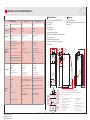
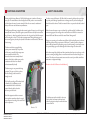
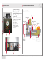
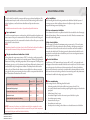
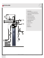
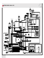
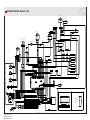
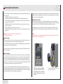
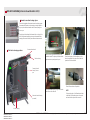
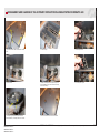
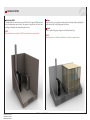
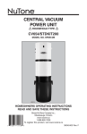
ARITERM-VTT-S-07229-11.1
ARITERM-VTT-S-07229-11.2
ARITERM-VTT-S-06765-11.1
ARITERM-VTT-S-06765-11.2
INSTALLATION AND OPERATING
INSTRUCTIONS
• Ariterm Biomatic+ 20i/40i
TABLE OF CONTENTS
General information..................................................................................... 2
Transport, storage and unpacking.............................................................. 2
Technical data............................................................................................... 3
Functional description.................................................................................. 4
Safety and alarms.......................................................................................... 4
Control panel................................................................................................. 5
Burner operating principle........................................................................... 5
Boiler installations........................................................................................ 6
Pipe installations........................................................................................... 7
Wiring diagram Biomatic+ 20i................................................................... 8
Wiring diagram Biomatic+ 40i................................................................... 9
Start-up and stop........................................................................................10
Burner settings............................................................................................11
Burner parts.................................................................................................11
Menu structure....................................................................................12 - 17
Heating circuit settings......................................................................18 - 19
Heat circuit settings and connections.......................................................20
Alarms and troubleshooting......................................................................21
Decommissioning.......................................................................................22
Most common spare parts.........................................................................22
Service and maintenance......................................................................23-26
Wood pellets as fuel....................................................................................27
Feeding system............................................................................................28
Declaration of conformity..................................................................29 - 30
Installation record.......................................................................................31
GENERAL INFORMATION
Ariterm Biomatic+ 20i/40i is a cost-effective, resistant, non-condensing and environmentally friendly central heating boiler intended for use for the heating of single-family detached
houses and the production of hot domestic water using pellets. Additional/backup heat is
produced by an immersion heater (9 kW, not in models L and UL). Standard equipment
includes an automatic convection cleaning system and an automatic heating circuit regulation
system. Detailed technical data can be found on page 3. To make use of all features of the
boiler and burner, it is important to observe these instructions.
Keep this manual in a safe place for future reference. Read this manual carefully before
starting to use your Ariterm Biomatic+ 20i/40i pellet heating unit. The power of the pellet
burner depends on how many pellets can be fed into and burned in the burner head during
one hour.
Please note! Follow the recommendations contained in this manual when using and servicing
the burner and the boiler.
TRANSPORT, STORAGE AND PACKAGE OPENING
Receipt and acceptance
The boiler is delivered in a wooden frame. The base is a platform from which the boiler can
be safely lifted. The package should be unwrapped as close to the installation site as possible.
It is important for the person who receives the boiler to verify the state of the boiler before
its acceptance. In case of damage, the dealer must be contacted without delay.
Storage
The boiler should be stored inside.
Package opening
After opening the packaging, open the hatch and check the accessory list to make sure that
all loose accessories are contained in the package (cleaning brush handles are attached to the
packaging).
Disposing of the package
The plastic cover is landfill waste and the boards can be burned.
ARITERM-VTT-S-07229-11.1
ARITERM-VTT-S-07229-11.2
ARITERM-VTT-S-06765-11.1
ARITERM-VTT-S-06765-11.2
ARITERM AB • ARITERM OY • Asennus ja käyttöohje • Installation och driftanvisning • Installation and operating instruction • 04.08.2015 • 2/32
TECHNICAL DATA ARITERM BIOMATIC+
Class according to EN303-5 2012
class 5
class 5
Performance
Power with pellets
Combustion efficiency
Noise level
6-20 kW
91%
62 dbA
12-40 kW
93%
62 dbA
Dimensions
Dimensions (width x depth x height)
Empty weight
Water volume
601 x 944 x 1,509 mm
245 kg
140 l
606 x 1350 x 1618 mm
455 kg
173 l
Working pressure: boiler
Working pressure: heat exchanger*
Working temperature*
0.5-1.5 bar
max 10 bar
max 120 o C
0.5 - 2.5 bar
max 10 bar
max 120 o C
Production of hot tap water*
*Not applicable for Ultra-Light model
1-shower ( 12 l/min),
520 l/+40 C )
2-shower ( 20 l/min, 240 l/+40 C )
1-shower ( 12 l/min),
continously/+40 C )
2-shower ( 20 l/min, 400 l/+40 C )
Flue gas temperature nominal output
Flue gas temperature minimum output
Flue gas mass flow nominal output
Flue gas mass flow minimum output
109 oC
65 oC
11,5 g/s
4,0 g/s
132 oC
76 oC
19,6 g/s
8,6 g/s
Additional heating circuit unit
Domestic water
Expansion
Discharge
Flue pipe connection
Pressure drop - connections
DN 25 male
Cu Ø 22 mm
DN 25 male
DN 15 female
Ø 102 mm
2 mbar @ 0,86 m3/h
11 mbar @ 1,72 m3/h
DN 25 male
Cu Ø 22 mm
DN 25 male
DN 15 female
Ø 140 mm
15 mbar @ 1,72 m3/h
58 mbar @ 3,44 m3/h
Power supply
Standard model 400V, 3N~, 50 Hz
Light & Ultra-Light model 230V, 1N~,
50 Hz
Standard model 400V, 3N~, 50 Hz
Light & Ultra-Light model 230V, 1N~,
50 Hz
Fuse size
Standard model 9 kW immersion,
3x16 A
Light & Ultra-Light model <1 kW immersion, 1x6 A
Standard model 9 kW immersion,
3x16 A
Light & Ultra-Light model <1 kW immersion, 1x6 A
Power in operation
Burner, ignition 500 W
Burner, normal 40 W
Burner, ignition 560 W
Burner, normal 60 W
19 W
19 W
Connections
Electrical
values
Power consumption - standby
20
2
12
15
1
14
130 (119)
230 (245)
11
10
935 (1350)
9
3
5a
8
4
5b
7
Dimensions of Ariterm Biomatic+ 20i & Ariterm Biomatic+ 40i.
Dimensions in parentheses specific dimension of Ariterm Biomatic+ 40i.
1
2
3
4
5a
6
ARITERM-VTT-S-07229-11.1
ARITERM-VTT-S-07229-11.2
ARITERM-VTT-S-06765-11.1
ARITERM-VTT-S-06765-11.2
13
515
Design and
adjustment
values
608
1505
Boiler class
Accessory
• Combined flue duct
• Shunt valve, motor and control for additional
heat circuit
1755
Biomatic+ 40i
1555 (1543)
Biomatic+ 20i
TECHNICAL DATA
Standard delivery
• Four-way mixing valve ESBE TM 20
• Sweeping gear
• Dirt trap
• Brick support
• Flue duct joint
• Oxygen sensor regulation
• Shunt motor unit incl. Wireless Room unit
• Flow water sensor
• Outdoor temperature sensor
• Automatic convection cleaning system
• Flow switch
5b
Drain valve DN 15, internal thread
Flue
Connection for extra heating circuit
DN 25, external thread
Connection for expansion DN 25,
external thread
Outlet to heating circuit from
4-way mixing valve
Return from heating circuit to
4-way mixing valve
8
9
10
11
12
13
14
Electrical connections
Cleaning hatch
Ash box
Return DN 25, internal thread
Display/keypad
Automatic convection cleaning
Flue gas fan
15
Temperature sensors
ARITERM AB • ARITERM OY • Asennus ja käyttöohje • Installation och driftanvisning • Installation and operating instruction • 04.08.2015 • 3/32
FUNCTIONAL DESCRIPTION
SAFETY AND ALARMS
Heating with the Ariterm Biomatic+ 20i/40i pellet heating unit is similar to oil heating in
many ways. The main difference is that heating with solid fuel produces a certain amount of
ash, which must be removed at certain intervals. If the ash is not removed, combustion efficiency will decrease and the burner may malfunction.
For safety reasons, the Biomatic+ 20i/40i and fuel store must be placed apart from each other
to prevent possible damage. Any malfunctions or damages caused by incorrect handling will
then be limited to the burner. The fuel store must be built as a separate, fire-classified, confined
space.
The BeQuem pellet burner is equipped with automatic ignition. However, it can also be ignited
manually when necessary. The electric ignition system of the burner will only be activated during cold starts, i.e., when the system has been inactive for a long period and the boiler temperature has dropped to at least 7°C below the target temperature. During the heating process,
the necessary ignition cycles take place by means of the embers in the burner head. This saves
electric energy.
Faults that cause the system to stop are indicated by a red indicator light. In addition to this,
a text message appears in the web app and an email will be sent if the boiler is connected to
internet AND email addresses are added in menu “Alarm: Manage emails”.
The burner and the incorporated feeding
system operate automatically. The operation
of the burner is controlled by the temperature
sensor installed in the boiler. The
burner head contains an accurately defined
mixture of fuel and air, which ensures perfect
combustion which is both cost-effective
and environmentally friendly.
During every operating cycle, a small amount of pellets is fed from the pellet store via the external feeding system to the upper connection of the burner. To make it possible to dispense an
accurate and equal amount of pellets during every cycle, the dispensing is carried out by means
of a separate feeding auger via the blocking feeder and burner auger to the burner head.
As the burner auger feeds pellets forward three times faster than they arrive at the auger, a safety zone, containing only single pellets, is created between the burner head and the upper connection. This safety zone always remains intact even in the event of power failure, insufficient
maintenance or equipment breakage.
Alarms are described in “Alarms and troubleshooting”.
The burner auger is over-pressurised during
operation. The purpose of this is to reduce
the risk of damage to the burner if the
draught is weak.
Wood pellets according to EN standards with
a diameter of 6 or 8 millimetres are the
recommended fuel for the boiler. Ash is
removed from the ash box located in
the lower part of the boiler.
Standard equipment includes an automatic
heat regulation system that adjusts the supply
water temperature according to the outdoor and
indoor temperature.
The feeding auger must be installed in such a way
that its position, with respect to the drop funnel,
allows the drop pipe to swing free outside the burner
in case of back fire.
Biomatic+ 20i
Biomatic+ 20i
ARITERM-VTT-S-07229-11.1
ARITERM-VTT-S-07229-11.2
ARITERM-VTT-S-06765-11.1
ARITERM-VTT-S-06765-11.2
ARITERM AB • ARITERM OY • Asennus ja käyttöohje • Installation och driftanvisning • Installation and operating instruction • 04.08.2015 • 4/32
BURNER OPERATING PRINCIPLE
CONTROL PANEL
1. Actual boiler temperature
2. Immersion heater on/off
3. Tap water pump on/off
4. Burner control switch on/off/reset
5. Status LED green/red
No light = OFF
Green 1 s on 3 s off = Standby
Green 3 s on 1 s off = Ignition
Green = Operation
Red = Alarm
6. Cut out thermostat
7. Back up Thermostat
8. Tap water pump Fuse
9. Main fuse
1
The picture shows 20 kW burner.
Upper connection
Dispening auger
Ignition resistance
Blocking feeder
Primary air pipe
Ignition pipe
2
3
4
5
Safety zone
against fire
in the back
Fan
Auger Burner
Pellets are fed
to the burner head from
below
(underfeeding principle)
9
8
6
ARITERM-VTT-S-07229-11.1
ARITERM-VTT-S-07229-11.2
ARITERM-VTT-S-06765-11.1
ARITERM-VTT-S-06765-11.2
7
ARITERM AB • ARITERM OY • Asennus ja käyttöohje • Installation och driftanvisning • Installation and operating instruction • 04.08.2015 • 5/32
BOILER INSTALLATIONS
BOILER INSTALLATIONS
The boiler should be installed by a company with the proper professional qualifications. The
installation must always be carried out in accordance with, at the time being, valid local standards and regulations, as well as the Ariterm Installation and Operation Instructions..
NOTE!
All electrical connections must be carried out by a professionally-qualified electrician.
Space requirement
The boiler room must always meet, at the time being, valid local standards and regulations. At
least one meter of free space is recommended to be left in front of the boiler for cleaning and
maintenance operations. It is also recommended to leave about 40 cm of free space on each side
and at least 50 cm above the boiler.
NOTE!
The boiler must located be at a distance of no less than 180 mm from the back wall. In addition, it
must be possible to remove the flue gas fan whenever maintenance requires it.
Flue pipe connection and combustion air intake
Silicon sealant with a temperature resistance of 350°C can be used as a sealing compound for
joints. The flue pipe must be made of steel or equivalent material. The flue pipe length must be
dimensioned according to the building requirements. The low temperature of the flue gas from
the Biomatic gives rise to a risk of condensation in the chimney. Make sure the chimney is well
ventilated with the help of draught diverter/inhibitor The chimney flue should be stainless
steel or acid-proof. Ensure that the chimney connection (boiler flue to chimney connection)
is air tight since, during certain operating cases, there could be an overpressure after the boiler
flue. The ventilation air intake must not be covered.
Pipe installations
Before installing the boiler, the heating network must be flushed and checked by means of
a water-pressure test. After installation, make sure that all joints are tight. Ariterm is not
responsible for damages caused by leaking joints.
Dirt trap and manometer installation
It is recommended that the dirt trap delivered with the boiler is installed in the cold water pipe
before the heat exchanger. There is no manometer in the boiler. Therefore, a manometer must
be installed in the heating network.
Safety valve installation
The valve must be CE marked. Its maximum opening pressure must be 1.5 bar and its minimum size DN 15. The safety valve must be chosen according to the highest pressure class of
the combination of devices. Devices that can close the connection must not be installed between the valve and the boiler. The release pipe must be dimensioned and installed in such a
way that it does not limit the valve release efficiency and does not cause dangerous situations
during the operation of the valve.
Electrical installations
A pellet burner, a 9 kW immersion heater (not in models L and UL) and an internal circulation pump with its switches are installed in the boiler and are ready for use. The boiler contains
an overheat protection for the burner and the immersion heater. The electrical installations
related to the boiler must be carried out by an installer with the relevant qualifications and the
boiler must be connected according to the enclosed connection diagram. A safety/maintenance
switch must be installed in the voltage supply system of the boiler.
Flue pipe connection and ventilation air intake
Biomatic+ 20i
Biomatic+ 40i
Recommended flue pipe diameter
Ø 100 mm
Ø 140 mm
Recommended flue pipe length
4m
4m
Recommended underpressure* in the combustion chamber
3-15 Pa
3-15 Pa
Ventilation air intake
100 cm2
200 cm2
Recommended under pressure in the chimney
>0
>0
* Measure the vacuum in the measurement hole on the left-hand side of the burner. Remove the black screw
NOTE! The vacuum in the chimney is not critical because the boiler is equipped with a suction
fan. However, it must be dimensioned to be able to evacuate the flue gases without overpressure
occurring as the flue gases could then leak into the building.
ARITERM-VTT-S-07229-11.1
ARITERM-VTT-S-07229-11.2
ARITERM-VTT-S-06765-11.1
ARITERM-VTT-S-06765-11.2
Before commissioning
Before starting the boiler, the following should be checked:
• the heating network and the boiler are full of water (pressure at least 0.5 bar).
• air is removed from the internal circulation pump through the venting screw located in the
pump head.
• the flue damper (if any) is open.
• the circulation damper located in the convection part of the boiler is in place.
• the circulation pump is running.
• the network valves are open.
• the ventilation air intake is open.
• the safety valve is in working order and there are no obstacles between it and the boiler.
ARITERM AB • ARITERM OY • Asennus ja käyttöohje • Installation och driftanvisning • Installation and operating instruction • 04.08.2015 • 6/32
PIPE INSTALLATIONS
1. ARITERM BIOMATIC+
2. 4-WAY VALVE, FLOOR HEATING (RADIATOR HEATING)
3. CONNECTION SET OF THE ADDITIONAL HEATING CIRCUIT
(RADIATOR HEATING)
4. HEAT PIPE PUMP, FLOOR HEATING
5. HEAT PIPE PUMP, RADIATOR HEATING
6. FLOOR HEATING NETWORK MANIFOLDS
7. RADIATOR HEATING NETWORK
8. EXPANSION VESSEL
9. SERVICE SHUT-OFF VALVE
10. SAFETY VALVE
11. FILLING VALVE
12. FEED MIXING VALVE
ARITERM-VTT-S-07229-11.1
ARITERM-VTT-S-07229-11.2
ARITERM-VTT-S-06765-11.1
ARITERM-VTT-S-06765-11.2
ARITERM AB • ARITERM OY • Asennus ja käyttöohje • Installation och driftanvisning • Installation and operating instruction • 04.08.2015 • 7/32
WIRING DIAGRAM - Biomatic+ 20i
Charge pump
SW. w. pump
Brown
Brown
L1 L2 L3 N
PE
Tap water pump
Black
Blue
Yellow/green
External auger
Blue
Filter
Flue gas
Sensor
Boiler
Sensor
Blue
Convection cleaning
Red
Blue
Relay
Cut out
Thermostat
Fan 3
Red
Yellow/green
Contactor
C°
Thermostat
A1
Blue
C°
Black
1
A2
Immersion heater
P
Black
Black
Black
Black
Black
Black
Black
Main fuse
A
Black
10 3
4
7
6
9
2
5
8
1
Black
Burner auger
SW. on/off
LED R/G
Red
Black
Brown
SW. Imm. heater
Red
Red
Black
Fan 1
J26
J105
Black
J101
Yellow/green
J24
J4
J23
B
Oxygen sensor
Ignition element
Brown
Blue
White
Grey
Red
Black
J10
Grey
Black
Red
Black (white)
White
Yellow
Black (yellow)
Black (orange)
Orange
Flame sensor
Level
sensors
Circulation pump
Tank sensor (bottom)
J103
J104 J25
J6
J28
J27
ARITERM-VTT-S-07229-11.1
ARITERM-VTT-S-07229-11.2
ARITERM-VTT-S-06765-11.1
ARITERM-VTT-S-06765-11.2
L
5
6
2
J5
Brown (2x)
Alarm relay
Blue
Blue
Brown
Blue
Brown
Brown
Black
Black
Red
Red
B
White
Red
L
N
Black
Brown
Black (2x)
PE
Com
Red
PSU
10 3
4
7
6
9
2
5
8
1
Brown
Blue
White
+12V
Com
Grey
Red
+5V
Black
4
3
1
5
6
2
Fuse w. pump
Black
N
1
A
Grey (2x)
CRB (ESBUS communication)
Tank sensor (top)
J102
4
3
Black
BM61011v1 140822
ARITERM AB • ARITERM OY • Asennus ja käyttöohje • Installation och driftanvisning • Installation and operating instruction • 04.08.2015 • 8/32
WIRING DIAGRAM - Biomatic+ 40i
Charge pump
SW. w. pump
Brown
Brown
L1 L2 L3 N PE
Tap water pump
Black
Blue
Yellow/green
External auger
Blue
Filter
Flue gas
Sensor
Boiler
Sensor
Blue
Convection cleaning
Brown
Red
Blue
Cut out
Thermostat
Fan 3
Relay
Red
Yellow/green
Contactor
C°
A2
Thermostat
Black
1
A1
Blue
C°
Immersion heater
P
Black
Black
Black
Black
Black
Black
Black
Main fuse
A
Black
10
Blue
9
3
5
4
2
7
8
6
1
Burner auger
Black
Black
SW. on/off
SW. Imm. heater
Fan 1
LED R/G
Red
Red
Red
Black
Brown
Black
Black
Fan2
J26
J105
Yellow/green
J101
J 24
J4
J 23
B
Oxygen sensor
Ignition element
Blue
Grey
Black
J10
Grey
Black
Red
Black (white)
White
Yellow
Black (yellow)
Black (orange)
Orange
Flame sensor
Level
sensors
Circulation pump
Tank sensor (bottom)
J103
J104
J25
J6
J28
J27
Alarm relay
ARITERM-VTT-S-07229-11.1
ARITERM-VTT-S-07229-11.2
ARITERM-VTT-S-06765-11.1
ARITERM-VTT-S-06765-11.2
5
2
4
1
6
A
B
Red
L
N
Black
Brown
Black (2x)
PE
Com
+12V
Com
Red
+5V
PSU
10
9
3
5
4
2
7
8
6
Blue
1
Grey
Black
Brown
White
Red
3
5
2
4
1
6
Fuse w. pump
Black
N
Red
White
Brown (2x)
Blue
Blue
Brown
Blue
Brown
Brown
Black
Black
Red
Red
White
3
J5
Grey (2x)
CRB (ESBUS communication)
Tank sensor (top)
J102
Brown
Black
L
ARITERM AB • ARITERM OY • Asennus ja käyttöohje • Installation och driftanvisning • Installation and operating instruction • 04.08.2015 • 9/32
BM61021v1 140821
START-UP AND STOP
Web interface function
(See separate section)
When the boiler arrives it is set as an AP (Access Point). You could connect to this by using your
WiFi unit, i.e. Smart phone, Computer, Tablet, iPad etc. When searching for accessable wifi-networks in your unit, a SSID called [serialnumberSSID] will appear. Choose that one and enter
password: ariterm123. Now you are connected to the boiler. Start your browser and you will
automaticly enter the Log in page in the boiler. Enter the user name (serialnumber of the boiler)
and the password (user). Now you can control the boiler by the web interface.
If you want to connect the boiler to internet, go to the Network menu choose your SSID, enter
your password. OBSERVE! Now you will leave the AP mode. Choose the same SSID on your
WiFi unit, start the browser. Enter [serialnumber].local and you are connected to the boiler
by your own network. If you use an Android device you may have to download the app. called
“Bonjour browser”. By using this app. you can find the boilers IP-adress. Then use this IP-adress
in your web browser to connect to the boiler. When the boiler is connected to the internet it will
start syncing with our server. Enter portal.aritermgroup.se (same user/password as above) in
your browser and you will have access to your boiler wherever you are.
Note! It is at this point strongly recommended to change password.
Burner start-up and stop
Turn the burner and the internal pump on from the operating switch. If the flow switch that
controls the internal pump is on, set the operating switch to Off mode. The first start-up differs
from normal start-up in that there are no pellets in the burner. Likewise, there are no pellets in
the external feeding system. Carry out the following actions in connection with the first start-up
or if there are no more pellets in the store:
1. Enter the menu “Settings/Pellets store”. Set “External feeder manual” to desired amount
of minutes to fill the feeder up. Click at “Update”. Repeat this intil the external feeder is filled
with pellets.
2. Press the burner control switch. Let the external auger run until the level sensors in the
burner indicates pellets. If the external auger operates longer than the maximum external
auger time, you have to reset the alarm and start again.
3. When the external auger is filled and the level sensors indicates pellets, the burner will
start.
ARITERM-VTT-S-07229-11.1
ARITERM-VTT-S-07229-11.2
ARITERM-VTT-S-06765-11.1
ARITERM-VTT-S-06765-11.2
Cold start
The burner performs a cold start with the ignition element when the boiler water
temperature is more than 7°C below the set value. The LED starts blinking green.
Shortly afterwards, the blower and the ignition element turn on. When the flame sensor detects
a flame in the burner head, the burner jumps directly to next start phase.
In the last start phase the burner stops. Do not change the settings during a cold start. After
cleaning the burner head, make sure that the burner performs a cold start because there are no
embers in the burner head. The success of the cold start can be ensured by sufficiently increasing
the set boiler water temperature and by changing it back to the desired value after ignition
Hot start
The burner performs a hot start when the boiler water temperature is within 8°C of the set
temperature, for example, after a short power failure. During a hot start, the burner uses the
embers in the burner head for ignition and, by doing so, saves energy. In normal use, when the
burner goes from “Glow mode” to Power mode, the burner performs a hot start. The burner
starts up automatically after power failures (hot or cold start depending on the temperature of
boiler water).
Power mode - Glow mode
After ignition, the burner starts using the High power mode. When the boiler water temperature
rises to within 5 ºC of its set value, the burner starts using the Low power mode and
will continue to use it until the set value is reached. When the set boiler water temperature
is reached, the burner blower still runs for one minute before the burner moves to Glow
mode. While the burner is in Glow mode, the auger burner brings pellets to the burner head
every now and then in order to maintain the embers.
Stop
The burner can be stopped at any stage of the combustion process. Set Burner to Off by pressing
the burner control switch. The blower will run for one minute after the burner has been
stopped.
ARITERM AB • ARITERM OY • Asennus ja käyttöohje • Installation och driftanvisning • Installation and operating instruction • 04.08.2015 • 10/32
Buffer tank mode
As an option two Buffer tank sensors and charge pump can be connected to the boiler. The
charge pump is to be connected to fast connectors labeled Charge pump and the tank sensor
to connectors labeled Tank sensor top/bottom. Put the Holding time setting to off-mode. The
burner’s starting- and stopping temperatures can now be set.
BURNER PARTS
The picture shows 20 kW burner.
5
12
1
11
In buffer tank mode the stop temperature is the temperature of the top sensor of the buffer tank,
read at ”Buffer tank sensor top” in the ”Home” menu, set at ”Stop temperature” in the ”Settings:
Main” menu. The start temperature is the temperature of the bottom sensor of the buffer tank,
read at ”Buffer tank sensor bottom” in the ”Home” menu, set at ”Start temperature (Degrees
below Stop temperature)” in the ”Settings: Main” menu. When the boiler temperature exceeds
the set charge pump start temperature, set at ”Tank pump start temperature” in the ”Settings:
Tank mode”menu, the charge pump will start. When the tank is warm and the burner stopped
the charge pump will turn off when boiler temperature has dropped 3 degrees below the set start
temperature of the charge pump. The return temperature shall be regulated, with a thermic
valve, to at least 60°C.
4
3
6
2
BURNER SETTINGS
8
Combustion adjustment
Normally you don’t need to do any combustion adjustments. The fan 1-3 is set to two
different power modes. High and Low. The oxygen sensor then regulates the fans and
adjust the pellet feeding automaticly. In a couple of ours you will have an optmized
combustion. If you want to lower the output please contact our local dealer.
Immersion heater operation (not in models L and UL)
According to default settings the immersion heater heats the boiler to “Immersion
heater stop temperature”. When the temperature drops “Immersion heater hysteresis”
degrees the immersion heater starts again. Alternatively, if ”Activate immersion heater
back-up mode” is set to ON the immersion heater will operate as back up according to
the boiler temperatures in the Main menu, IF the boiler is in Alarm mode.
ARITERM-VTT-S-07229-11.1
ARITERM-VTT-S-07229-11.2
ARITERM-VTT-S-06765-11.1
ARITERM-VTT-S-06765-11.2
10
7
9
1.
2.
3.
4.
5.
6.
Burner
Flame detection system
Level switch, receiver
Upper connection
Level switch, transmitter
Blower
7. Auger burner
8. Blocking feeder
9. Drive motor
10. Wheels and chain (not in the figure)
11. Primary air pipe
12. Connector panel
ARITERM AB • ARITERM OY • Asennus ja käyttöohje • Installation och driftanvisning • Installation and operating instruction • 11.06.2015 • 11/32
MENU STRUCTURE
Home
In the home menu you can see readings as follows:
The present operating mode of the burner, Burner set to On or Off, Sync status
Current boiler temperature, -Room temperature, -Outdoor temperature, -Pellet level in
storage, -Oxygen level, -Flow water temperature, -Buffer tank top temperature, -Buffer
tank bottom temperature, -Flue gas temperature, -Flame sensor level , -Number of warm
starts, -Number of cold starts, -Current maintenance time 1 & 2, - External feeder total
runtime.
ARITERM-VTT-S-07229-11.1
ARITERM-VTT-S-07229-11.2
ARITERM-VTT-S-06765-11.1
ARITERM-VTT-S-06765-11.2
Alarm
In the alarm menu you can see current alarm and are able to confirm them.
You can also see the history record of alarm and search.
ARITERM AB • ARITERM OY • Asennus ja käyttöohje • Installation och driftanvisning • Installation and operating instruction • 04.08.2015 • 12/32
MENU STRUCTURE
Manage emails
In the manage emails menu you can add new receivers of alarm emails and customize
them to each address.
ARITERM-VTT-S-07229-11.1
ARITERM-VTT-S-07229-11.2
ARITERM-VTT-S-06765-11.1
ARITERM-VTT-S-06765-11.2
Main
In the main menu you are able to set the boiler temperature (40 - 90°C) , room temperature and start and stop the burner.
ARITERM AB • ARITERM OY • Asennus ja käyttöohje • Installation och driftanvisning • Installation and operating instruction • 04.08.2015 • 13/32
MENU STRUCTURE
Maintenance
In the maintenance menu you are able to set two different alarm timers. When the external feeder has run set time you will get an email. (If email is added in alarm menu)
After each cleaning of the burner you should set the “Reset all adjustment values” to ON
and click “Update”.
ARITERM-VTT-S-07229-11.1
ARITERM-VTT-S-07229-11.2
ARITERM-VTT-S-06765-11.1
ARITERM-VTT-S-06765-11.2
Immersion heater
Here you can set start and stop temperature of the immersion heater.
If ”Activate immersion heater back-up mode” is set to ON the immersion heater will
operate as back up according to the boiler temperatures in the Main menu, IF the
boiler is in Alarm mode.
ARITERM AB • ARITERM OY • Asennus ja käyttöohje • Installation och driftanvisning • Installation and operating instruction • 04.08.2015 • 14/32
MENU STRUCTURE
Pellet store
Manage the pellet storage depending of size, storage type and set the alarm level.
Enter the external feeder feeding rate and the boiler calculates and alarms at certain level.
ARITERM-VTT-S-07229-11.1
ARITERM-VTT-S-07229-11.2
ARITERM-VTT-S-06765-11.1
ARITERM-VTT-S-06765-11.2
Tank mode
Activate tank mode when boiler is connected to a buffertank.
ARITERM AB • ARITERM OY • Asennus ja käyttöohje • Installation och driftanvisning • Installation and operating instruction • 04.08.2015 • 15/32
MENU STRUCTURE
Profile
In the profile menu you can edit you profile.
ARITERM-VTT-S-07229-11.1
ARITERM-VTT-S-07229-11.2
ARITERM-VTT-S-06765-11.1
ARITERM-VTT-S-06765-11.2
Network
In the network menu you are able to scan and select network if you dont want to use the
boiler as an AP (Access Point)
ARITERM AB • ARITERM OY • Asennus ja käyttöohje • Installation och driftanvisning • Installation and operating instruction • 04.08.2015 • 16/32
MENU STRUCTURE
Users
Here you can view all the users.
ARITERM-VTT-S-07229-11.1
ARITERM-VTT-S-07229-11.2
ARITERM-VTT-S-06765-11.1
ARITERM-VTT-S-06765-11.2
Create users
Here you can add new users. You are able to add users in the same user level as yourself
and lower.
ARITERM AB • ARITERM OY • Asennus ja käyttöohje • Installation och driftanvisning • Installation and operating instruction • 04.08.2015 • 17/32
HEATING CIRCUIT SETTINGS
Schedule
Here you can view the current schedule and select profile of room temperature.
ARITERM-VTT-S-07229-11.1
ARITERM-VTT-S-07229-11.2
ARITERM-VTT-S-06765-11.1
ARITERM-VTT-S-06765-11.2
Schedule
In the schedule profile you choose how to compose your week.
ARITERM AB • ARITERM OY • Asennus ja käyttöohje • Installation och driftanvisning • Installation and operating instruction • 04.08.2015 • 18/32
HEATING CIRCUIT SETTINGS
Schedule
In each profile you set the desired room temperatures and times.
ARITERM-VTT-S-07229-11.1
ARITERM-VTT-S-07229-11.2
ARITERM-VTT-S-06765-11.1
ARITERM-VTT-S-06765-11.2
ARITERM AB • ARITERM OY • Asennus ja käyttöohje • Installation och driftanvisning • Installation and operating instruction • 04.08.2015 • 19/32
HEAT CIRCUIT SETTINGS AND CONNECTIONS
CRB122 Shunt motor unit
Install the CRB122 unit by following the supplied manual. Connect the outdoor sensor
on the same connectors as the room sensor (A).
A
133mm
36,5 mm
60mm
36,5 mm
8mm
2 mm
B
69mm
C
X2
D
D
Circulation pump
Connect the PWM regulation cable from the circulation pump in the fast connectors,
blue on blue and brown on brown. (B)
Alarm relay
Relay output normally open. (C)
E
Buffer tank sensors
(D)
Main supply
(E)
Charge pump
Connect the buffer tank charge pump to this 230V output.(F)
F
Flow switch
Connect the flow switch here. If not, control the tap water pump with the tap water
switch on the panel.(G)
G
ARITERM-VTT-S-07229-11.1
ARITERM-VTT-S-07229-11.2
ARITERM-VTT-S-06765-11.1
ARITERM-VTT-S-06765-11.2
ARITERM AB • ARITERM OY • Asennus ja käyttöohje • Installation och driftanvisning • Installation and operating instruction • 04.08.2015 • 20/32
ALARMS AND TROUBLESHOOTING
Alarm message
Ignition failed
Action
Pellets haven’t reach up to the
ignition hole in the burner
cup.
Error, High Power Mode No flame during High
Control and/or clean the
power mode.
flame sensor.
Error, Low Power Mode
No flame during Low
Control and/or clean the
power mode.
flame sensor.
Alarm fan tachometer
No tacho pulses detected
Control the fan1 and the
from fan1.
cabling.
Max time external feeder The external feeder has
Check the pellets in the storalarm
been operating longer than age.
the maximum time.
Check the external auger
connector.
Control the level sensors in
the burner.
Max time internal feeder The internal feeder has
Control the level sensors in
alarm
been operating longer than the burner.
the maximum time.
Ignition elements are out The ignition output is not Check the ignition element
of order
consuming any current.
connections and/or the element resistance.
Alarm ESBUS communi- No communication from
Check internal and external
cation
CRB122 to boiler.
cabling.
Alarm power card comNo communication beCheck connector between
munication
tween RPi and power card. RaspberryPi and power card.
Alarm lost database
No data in the database.
Try to reboot the boiler by
pressing the boiler control
switch in 12 s, wait 12s, make
the boiler powerless and
power it up again.
Alarm flame or lambda
Flame or oxygen value is
Control and/or alter the
indicated in standby
indicated during standby.
flame sensor or the oxygen
sensor
ARITERM-VTT-S-07229-11.1
ARITERM-VTT-S-07229-11.2
ARITERM-VTT-S-06765-11.1
ARITERM-VTT-S-06765-11.2
Cause
The boiler didn’t ignite
during cold start.
Alarm message
Alarm safety circuit open
Cause
Action
The safety circuit to the
Control why the boiler has
cut out thermostat is open. been overheated. Lower
boiler temperature.
Check cabling to cut out
thermostat.
Low SD card memory left The SD card is nearly full. Contact your nearest Ariterm
dealer.
No SD card memory left The SD card is full.
Contact your nearest Ariterm
dealer.
Maintenance time 1
The total operating time
Clear the maintenance alarm
exceeded
of the external auger is
1 in the maintenance menu.
longer than the maximum
time alarm1 settings.
Maintenance time 2
The total operating time
Clear the maintenance alarm
exceeded
of the external auger is
2 in the maintenance menu.
longer than the maximum
time alarm2 settings.
Oxygen sensor failure
The oxygen sensor is faulty Contact your nearest Ariterm
dealer.
Warning Pellets level low
Low pellets level in the
storage.
Boiler temp reached high
temp limit.
The boiler is almost overheated.
Clear the alarm and fill the
storage with pellets. Remember to add pellets in the “Pellet store” menu as well.
Lower the stop temperature
or increase the speed of the
charge pump when using
tank mode.
ARITERM AB • ARITERM OY • Asennus ja käyttöohje • Installation och driftanvisning • Installation and operating instruction • 04.08.2015 • 21/32
GUARANTEE AND DECOMMISSIONING
MOST COMMON SPARE PARTS
Guarantee
For Warranty Issues Ariterm Sweden AB refers to our local Distributor.
Decommissioning
An end-of-life boiler is suitable for scrapping. Its plastic parts are landfill waste.
Biomatic+ 20i spare part list
ARITERM-VTT-S-07229-11.1
ARITERM-VTT-S-07229-11.2
ARITERM-VTT-S-06765-11.1
ARITERM-VTT-S-06765-11.2
Product no.
5936
5212
5787
5362
5358
6104
5820
5062
6103
6168
Description
Thermal protection
Gasket burner/boiler
Circulation pump, domestic hot water
Boiler temperature sensor
Flue gas temperature sensor
Raspberry Pi
ESBE ARA661 shunt motor
Motor aut. convection cleaning
Power card CC14
Outdoor temperature sensor ESBE
5346
5023
5831
5886
5421
5488
5036
5037
5486
5035
5939
5033
5360/5361
5359
Cogg drive Z=12, Locker feeder
Cogg drive Z=15, Motor
Cogg drive Z=24, Dosing screw
Chain, 79-link
Chain shackle
Feed motor
Primary air ring
Burn cup, outer mould
Locker feeder impeller
Burner screw
Combustion fan
Ignition element 450W
Level sensors
Optical sensor
Biomatic+ 40i spare part list
Product no.
5936
5213
5787
5362
5358
5820
5062
6168
6103
6104
5875
5831
5081
5346
5416
5886
5421
5307
5963
5328
5786
5935
1293
5308
5425
5415
5360+5361
5359
Description
Thermal protection
Gasket burner/boiler
Circulation pump, domestic hot water
Boiler temperature sensor
Flue gas temperature sensor
ESBE ARA661 shunt motor
Motor aut. convection cleaning
Outdoor temperature sensor
Power card CC14
Raspberry Pi
Cogg drive Z=17, Motor
Cogg drive Z=24, Dosing screw
Cogg drive Z=18, Burner screw
Cogg drive Z=12, Locker feeder
Ball bearing, burner auger
Chain, 79-link
Chain shackle
Feed motor
Primary air ring
Burn cup, lower part
Locker feeder impeller
Burner screw
Combustion fan2
Combustion fan1
Oil bronze bearing 12/18x8, for feed.auger and block.
feeder
Ignition element 450W
Level switches (incl. transmitter and receiver)
Optical sensor
ARITERM AB • ARITERM OY • Asennus ja käyttöohje • Installation och driftanvisning • Installation and operating instruction • 04.08.2015 • 22/32
SERVICE AND MAINTENANCE
The boiler and burner will function without problems for a long time if the following instructions are observed:
• The boiler must be kept in a dry environment
• The boiler and burner operate all the time within the defined adjustment values.
• Clean the boiler when the temperature of flue gases has increased by 20-30°C from the
temperature with a clean boiler.
• Check the burner head and clean it if needed. Remove any sintering and, if necessary,
scrape the air gaps open.
• Replace damaged parts with a new ones in due time
• Check to make sure that no condensed water or water coming from pipe leaks can damage the boiler.
Sintering is often due to impurities in the fuel. If this is the case, you should immediately file a
complaint with the fuel supplier. Pay special attention to pellet quality when you receive a new
delivery or when you change suppliers.
Note! After cleaning the burner, “Reset all adjustment values” in
“Settings: Maintenance” menu.
Note!
Always remember to be careful when dealing with ash because it may still be incandescent. The
ash must be stored in a fire-resistant vessel.
Boiler cleaning
Turn the burner off for about an hour before maintenance work. Clean the furnace from the
burner opening and the convection part from the cleanout hatch on the
top of the boiler. Clean all convection pipes with the cleaning brush delivered with the boiler
(see the next page). Finally, empty the ash box.
The interval for ash removal and boiler cleaning can be specified in the Maintenance menu on
the basis of experience.
Burner cleaning
Turn the burner off for about an hour before maintenance work. Disconnect and pull the burner out of the boiler, check the burner head and carry out the necessary operations. The burner
head does not usually need special maintenance. However, in connection with ash removal,
it is good to check whether hardened ash has accumulated in the burner head. To detach the
hardened ash, use a screwdriver or similar tool. At the same time, check whether ash has flown
to the opening of the flame detection pipe and clean it if needed.
In connection with a new fuel delivery, the burner head must be checked in order to detect
possible sintering (mutually bound ash, rock and gravel-like particles in the burner head) over
time. Such particles must absolutely be removed from the burner head at short intervals so that
the primary ring will not become overheated and get damaged.
ARITERM-VTT-S-07229-11.1
ARITERM-VTT-S-07229-11.2
ARITERM-VTT-S-06765-11.1
ARITERM-VTT-S-06765-11.2
Check every 1-2 years
Unfasten the burner primary air ring, which is fastened by means of four screws and nuts.
Clean the air vents of the primary ring and remove all ash. At the same time, check the primary
air pipe and clean it of ash. The burn cup should be sealed with fireproof sealant.
Detach the protective casing of the burner. Check the chain wheels and chains for wear or
whether the chain has loosened. Adjust and change as needed. Lubricate the chain with thin
oil.
Long nuts on both
sides of the burner
Burner slide bar
Ash box fastening handles
Burner cleaning is started by unfastening
the long nuts on both sides of the burner
and by pulling the burner out of the boiler.
Make sure that the burner wires do not get
damaged.
It is recommended to have the ash box open
when cleaning the burner cup.
ARITERM AB • ARITERM OY • Asennus ja käyttöohje • Installation och driftanvisning • Installation and operating instruction • 04.08.2015 • 23/32
BOILER CLEANING (pictures show Biomatic+ 40i)
Automatic convection cleaning system
The boiler is equipped with automatic convection cleaning system
that automatically carries out the sweeping at certain intervals. In
any case, the convection channels must be cleaned (swept) two
times a year.
The cleaning is done through the cleanout hatch on the top of the
boiler. The automatic sweeping system must be removed before
sweeping. Disconnect the main power before maintenance work.
Other boiler cleaning operations
Convector cleanout hatch
Flue duct cleaning
Remove all ash and possible sintering from the
combustion vessel. The primary air intakes and the
ignition resistance opening must be open.
Clean the metal pipe of the flame detector so that
the ash accumulated in the pipe will not hinder the
operation of the flame detector.
Convection channel
cleaning 2 times a
year.
Clean the flame detector of impurities.
Pull the flame detector out of its pipe with caution
and hold on to the rubber lid.
Combustion chamber cleaning
(as needed)
NOTE!
If the protective glass of the flame detector breaks
or detaches, the flame detector can no longer be
used and must be replaced with a new one.
Ash box emptying
ARITERM-VTT-S-07229-11.1
ARITERM-VTT-S-07229-11.2
ARITERM-VTT-S-06765-11.1
ARITERM-VTT-S-06765-11.2
ARITERM AB • ARITERM OY • Asennus ja käyttöohje • Installation och driftanvisning • Installation and operating instruction • 04.08.2015 • 24/32
DISSASEMBLY AND CLEANING OF THE AUTOMATIC CONVECTION CLEANING SYSTEM OF BIOMATIC+ 20i
1. Open the outer and intermediate star knobs and lift
off the soot hatch.
2. Lift the lift lever up.
3. Lift the rocker switch to the side.
4. Lift the lift lever up, remove the hatch for the
convection channel.
5. Lift off the second hatch of the convection channel.
6. Lift off the holder and the springs from the convection.
7. Sweep the convection pipe surface with a brush,
remove any ash. Push the brush up and down again.
ARITERM-VTT-S-07229-11.1
ARITERM-VTT-S-07229-11.2
ARITERM-VTT-S-06765-11.1
ARITERM-VTT-S-06765-11.2
8. Reinstall all the springs and lifting levers illustrated.
9. Install the convection channel hatch and the rocker
switch.
10. Install the soot hatch and screw in the star knob.
ARITERM AB • ARITERM OY • Asennus ja käyttöohje • Installation och driftanvisning • Installation and operating instruction • 04.08.2015 • 25/32
DISSASEMBLY AND CLEANING OF THE AUTOMATIC CONVECTION CLEANING SYSTEM OF BIOMATIC+ 40i
1. Open the outer star knobs and remove the cleanout
hatch.
2. Convection part
3. Pull all the spirals out.
4. Spirals removed
5. Sweep the convection tube surfaces with a round
brush and remove fly ash. Insert the brush all the way
down and lift back up.
6. Fit all the spirals in place.
7. Clean the flu gas blower blades and remove ash
from the blower box, for example, with an ash vacuum.
8. Attach the cleanout hatch and fit the star knobs.
ARITERM-VTT-S-07229-11.1
ARITERM-VTT-S-07229-11.2
ARITERM-VTT-S-06765-11.1
ARITERM-VTT-S-06765-11.2
ARITERM AB • ARITERM OY • Asennus ja käyttöohje • Installation och driftanvisning • Installation and operating instruction • 04.08.2015 • 26/32
WOOD PELLETS AS FUEL
Wood pellets are renewable bioenergy and provide fuel in a compact and uniform form, which
is easy to handle. The moisture content is less than 10%, which means that the pellets do not
freeze or become mouldy. No chemical substances are used in the manufacturing process. Instead, the binding agent is the tree’s own lignin.
The pellet diameter is 6 to 8mm and the length is 10 to 30 mm. Due to their small size, the
pellets move freely in the feeding augers.
NOTE!
The Ariterm Biomatic + series boilers are suitable for burning pellets of diameters ranging from
6mm through to 8mm. The burner is factory set for 6mm wood pellet.
Most of the disturbances that occur as a result of bad fuel quality are caused by incorrect handling and intermediate storage before the product is delivered to the customer. Large contents
of fine materials may be due to insufficient sifting. Ash sintering is often caused by silicate
impurities (sand). These materials cannot be detected before burning. NOTE! If the ash is sintered, all sintered material must be continuously removed from the burner head.
Fuel recommendation
Raw material
Chemically untreated, barkless wood
Diameter
6-8 mm
Length
10-30 mm
Volume weight
over 600 kg/m3
Moisture content
less than 10%
Ash content
less than 0.7 weight %
Fine material content
max 4 weight %
Ash melting temperature
> 1,100 °C
Energy content
>4.75 kWh/kg
Fuel storage
Thanks to the feeding system, it is possible to build the pellet store for so-called bulk deliveries.
The store can be placed either inside or in a separate building outside the house. The shorter
the transport distance from the store to the burner, the better the feeding system functions.
Fire regulations must be taken into consideration when designing the boiler room and the storage area.
The entire store must be insulated with extreme caution in order to prevent dust from spreading.
The pellet delivery methods must be taken into account when choosing the store size. In
general, the pellets can be obtained in small sacks (20 kg), large sacks (500 kg) or directly to
thestore by means of a blower truck. One ton of pellet fuel requires about 1.6 m3 of storage
space. A store of 8 to 10 cubic metres is a reasonable solution for many houses and involves
lower delivery costs.
NOTE!
Pellet should be stored in a dry place.
ARITERM-VTT-S-07229-11.1
ARITERM-VTT-S-07229-11.2
ARITERM-VTT-S-06765-11.1
ARITERM-VTT-S-06765-11.2
ARITERM AB • ARITERM OY • Asennus ja käyttöohje • Installation och driftanvisning • Installation and operating instruction • 04.08.2015 • 27/32
FEEDING SYSTEM
Weekly silo PF450
The lightweight silo is an alternative to the self-built silo. The practical PF450 may also
be used as intermediate store for pellets. The capacity of the pellet silo is 450 litres and
its filling is facilitated by the intermediate grid in the silo.
NOTE!
More information on the installation of PF450/Feedo can be found in separate manuals.
ARITERM-VTT-S-07229-11.1
ARITERM-VTT-S-07229-11.2
ARITERM-VTT-S-06765-11.1
ARITERM-VTT-S-06765-11.2
Depo
Feed chute Depo is a patented pellet transfer system that effectively, reliably and quietly feeds
pellets from the silo via the feeding system to the burner.
Feedo
Feedo is a pellet feeding system designed to work with feed chute Depo.
NOTE!
More information on the installation of Depo/Feedo can be found in separate manuals.
ARITERM AB • ARITERM OY • Asennus ja käyttöohje • Installation och driftanvisning • Installation and operating instruction • 04.08.2015 • 28/32
ARITERM-VTT-S-07229-11.1
ARITERM-VTT-S-07229-11.2
ARITERM-VTT-S-06765-11.1
ARITERM-VTT-S-06765-11.2
Staffan LundegŒrdh, Managing Director
Kalmar 2015-04-20
- The boiler meets requirements for emission class 5 -
¥ EN 61000-6-3:2007, -3-2:2006, -A1:2009, -A2:2009, -3-3:2008, Emission by electromagnetic
disturbances.
¥ EN 61000-6-2:2005, -4-2, -3, -4, -5, -6, -11, Immunity to electronic disturbances.
¥ EN ISO 14121-1 Risk assessment
¥ EN 60335-1:1994 Safety of household and similar appliances - Part 1: General requirements.
¥ EN 303-5:2012 Heating boilers for solid fuels, manually and automatically stoked, nominal
heat output of up to 500 kW - Terminology, requirements, testing and marking
The conformity was checked in accordance with the following EN-standards
…verensstŠmmelsen Šr kontrollerad i enlighet med fšljande EN-standarder
Die KonformitŠt wurde ŸberprŸft anhand der EN-Normen
Yhdenmukaisuus on tarkastettu seuraavien EN-standardien mukaan
EMC Directive 2004/108/EY
Low Voltage Directive 2006/95/EC
Machinery directive 2006/42/EC
Pressure vessels 97/23/EG (H-module, notiÞed body 0424)
to which this declaration relates are in conformity with requirements of the following directives:
som omfattas av denna fšrsŠkran Šr i šverensstŠmmelse med fšljande direktiv:
auf das sich diese ErklŠrung bezieht, konform ist mit den Anforderung der Richtlinien:
jota tŠmŠ vakuutus koskee on yhteensopiva seuraaviin mŠŠrŠyksiin
- Ariterm Biomatic+ 20i
- Ariterm Biomatic+ 40i
declare under our sole responsibility that the products / fšrsŠkrar under eget ansvar att produkterna
erklŠren in alleiniger Verantwortung, da§ die Produkten / vakuuttaa omalla vastuulla ettŠ tuote
Ariterm AB
FlottiljvŠgen 15
S-39241 KALMAR
Declaration of conformity / FšrsŠkran om šverensstŠmmelse
KonformitŠtserklŠrung / Vaatimuksenmukaisuusvakuutus
DECLARATION OF CONFORMITY
ARITERM AB • ARITERM OY • Asennus ja käyttöohje • Installation och driftanvisning • Installation and operating instruction • 04.08.2015 • 29/32
DECLARATION OF CONFORMITY
The Clean Air Act 1993 and Smoke Control Areas
Under the Clean Air Act local authorities may declare the whole or part of the district of the
authority to be a smoke control area. It is an offence to emit smoke from a chimney of a building, from a furnace or from any fixed boiler if located in a designated smoke control area. It is
also an offence to acquire an “unauthorised fuel” for use within a smoke control area unless it is
used in an “exempt” appliance (“exempted” from the controls which generally apply in the smoke
control area).
The Secretary of State for Environment, Food and Rural Affairs has powers under the Act
to authorise smokeless fuels or exempt appliances for use in smoke control areas in England.
In Scotland and Wales this power rests with Ministers in the devolved administrations for
those countries. Separate legislation, the Clean Air (Northern Ireland) Order 1981, applies in
Northern Ireland. Therefore it is a requirement that fuels burnt or obtained for use in smoke
control areas have been “authorised” in Regulations and that appliances used to burn solid fuel
in those areas (other than “authorised” fuels) have been exempted by an Order made and signed
by the Secretary of State or Minister in the devolved administrations.
Further information on the requirements of the Clean Air Act can be found here : http://
smokecontrol.defra.gov.uk/
Your local authority is responsible for implementing the Clean Air Act 1993 including designation and supervision of smoke control areas and you can contact them for details of Clean Air
Act requirements
The Ariterm Biomatic+ series boilers have been recommended as suitable for use in smoke
control areas when burning wood pellets.
ARITERM-VTT-S-07229-11.1
ARITERM-VTT-S-07229-11.2
ARITERM-VTT-S-06765-11.1
ARITERM-VTT-S-06765-11.2
ARITERM AB • ARITERM OY • Asennus ja käyttöohje • Installation och driftanvisning • Installation and operating instruction • 04.08.2015 • 30/32
INSTALLATION REPORT
Flue gas temperature - Max
CO
O2
CO2
Combustion efficiency
Draught mm
Blower %
Auger %
Flue gas temperature - Mean
CO
O2
CO2
Combustion efficiency
Draught mm
Blower %
Auger %
Flue gas temperature - Min
CO
O2
CO2
Combustion efficiency
Draught mm
Blower %
Auger %
Dealer / Installer
Installer
Date
ARITERM-VTT-S-07229-11.1
ARITERM-VTT-S-07229-11.2
ARITERM-VTT-S-06765-11.1
ARITERM-VTT-S-06765-11.2
ARITERM AB • ARITERM OY • Asennus ja käyttöohje • Installation och driftanvisning • Installation and operating instruction • 04.08.2015 • 31/32
ARITERM-VTT-S-07229-11.1
ARITERM-VTT-S-07229-11.2
ARITERM-VTT-S-06765-11.1
ARITERM-VTT-S-06765-11.2
ORGANISATION
CERTIFIED BY
ARITERM SWEDEN AB | Flottiljvägen 15
39241 Kalmar | www.ariterm.se | 0771-442850