1
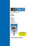
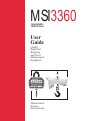
MSI3360
CHALLENGER 2
CRANE SCALES
User
Guide
Quality
Industrial
Weighing
and Force
Measurement
Equipment
Measurement Systems International
2
CHALLENGER
1
0
MODEL 3360
Seattle, Washington U.S.A.
LO BATT
2
NET
PEAK
TOTAL
GROSS
5000 x 2 kg
POWER
MOTION
X1000
10000 x 5 lb.
0
T
ZERO
TARE
USER
Measurement
Systems
International
M E A S U R E M E N T
S Y S T E M S
I N T E R N A T I O N A L
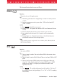
IMPORTANT
Please read this manual carefully before using the MSI-3360 Challenger 2
Program Number
Capacity and Resolution
Serial Number
Cal Number
Page 2
MSI-3360 Challenger 2
•
User Guide
M E A S U R E M E N T
S Y S T E M S
I N T E R N A T I O N A L
TABLE OF CONTENTS
Introduction ............................................................ 4
Specifications ......................................................... 4
Features ................................................................... 6
Options ................................................................... 7
Unpacking ............................................................... 7
Assembly ................................................................ 7
Battery Pack ............................................................ 8
Battery Charger ....................................................... 9
Operation Guide ................................................... 10
POWER ................................................................ 11
ZERO .................................................................... 11
TARE .................................................................... 12
USER .................................................................... 13
TEST (tESt) .......................................................... 13
Accessing the Service Counters ........................... 14
To Reset the Service Counter ............................... 15
TOTAL (totAL) ................................................... 15
Manual TOTAL .................................................... 15
Auto TOTAL ........................................................ 16
To Clear the Last Totaled Weight ......................... 17
To Clear the TOTAL Value ................................... 17
Viewing TOTAL ................................................... 17
UNIT (kg/lb) ......................................................... 18
PEAK (Phold) ....................................................... 18
NET/GROSS (nEtGr) ........................................... 19
Scale Setup ........................................................... 19
Quick USER Setup Guide .................................... 20
Function (Func) .................................................... 21
Automatic Power Off (A-OFF) ........................... 21
Filter (Filtr) .......................................................... 22
LED Brightness (LEdS) ...................................... 22
Unit (kg/lb) .......................................................... 23
Setpoints (StPt1, StPt2) ........................................ 23
Set Point Entry ...................................................... 23
To Disable a Set Point .......................................... 24
TOTAL (totAL) .................................................... 25
System Initialize ................................................... 25
Calibration Setup .................................................. 26
Quick Calibration Setup Guide ............................ 27
Calibration (CAL) ................................................ 27
Initial Calibration .................................................. 27
Subsequent Calibration ......................................... 29
Fine Calibration (F-CAL) ..................................... 29
Calibration with Calibration Offset Resistor
(CAL-r) ................................................................. 30
Standards (StAnd) ............................................... 31
Remote Control (r-Ctl) ......................................... 31
Auto ZERO Tracking (AZt) ................................. 32
INFRARED REMOTE OPTION ......................... 33
Introduction .......................................................... 33
Remote Controller Operation ............................... 34
To Enable Remote Controller ............................... 34
Batteries ................................................................ 34
To Set Remote Controller Access Codes .............. 35
The Scale and 2nd Keys ....................................... 35
POWER ................................................................ 36
ZERO .................................................................... 36
TARE .................................................................... 36
RECALL TARE .................................................... 36
NET/GROSS ........................................................ 36
USER .................................................................... 36
UNITS .................................................................. 37
TOTAL ................................................................. 37
VIEW TOTAL (VIEW ∑) .................................... 37
Clear Last Total .................................................... 37
Clear All Totals ..................................................... 38
Keyboard Tare ...................................................... 38
Display Key .......................................................... 39
SETPOINTS ......................................................... 39
ID # ....................................................................... 40
PRINT ................................................................... 40
SETUP .................................................................. 40
Troubleshooting Guide ......................................... 42
Service Counter Warning ...................................... 44
The MSI Limited Warranty .................................. 45
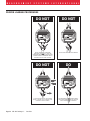
Proper Loading Procedures .................................. 46
MSI-3360 Challenger 2
•
User Guide
Page 3
M E A S U R E M E N T
S Y S T E M S
I N T E R N A T I O N A L
INTRODUCTION
The MSI-3360 Challenger 2 is a combination of the sound and proven mechanical design of the original Challenger with today’s most advanced electronics to provide a superb feature set unmatched by any scale in its class or price
range. The multi-purpose hanging scale is ideal for situations in which headroom is at a minimum. The Challenger 2 is versatile, reliable, accurate and easy
to operate.
SPECIFICATIONS
Accuracy:
Resolution:
Capacities:
lb
kg
Power:
0.1% of applied load ± one displayable increment
Standard displayed resolution: 2500 counts Internal A/D
resolution: 1,048,576 counts (20 bits)
250
500
1000
2000
5000
10,000 15,000
125
250
500
1000
2500
5000
7500
Battery operated, rechargeable sealed lead acid battery pack
(standard Challenger Charger); up to 100 hours of battery life
with Automatic Sleep Mode and Automatic Power Off
Display:
5 digit, large 1.2 in (30 mm) high numeric red GaAIAs Light
Emitting Diode (LED)
Operating Temperature:
- 4°F to +122°F (-20°C to +50°C) NTEP range -10°C to +40°C
Operating Time:50 hours min./100 hours max. (depends on operating mode)
Enclosure:
NEMA 12/IP54 powder coated alodined cast aluminum
Load Cell:
Standard 350 Ω Bridge
Indicators:
LO BATT, PEAK, MOTION, Center of ZERO, NET,
GROSS, TOTAL, X1000, kg/lb, StPt1, StPt2
Function buttons:
POWER:
Turns scale on and off
ZERO:
Zeros applied load up to 100% of capacity
TARE:
Tare In stores current GROSS weight as TARE. All subsequent readings are Net Weight. Tare Out returns the weight
display to GROSS Mode
USER:
Programmable multifunction button for use as TEST,
TOTAL, UNIT, PEAK, NET/GROSS
Front panel calibration switch (located behind seal screw):
Initiates full digital calibration procedure
User button options:
TEST (default), TOTAL, UNIT, PEAK, NET/GROSS, OFF
Page 4
MSI-3360 Challenger 2
•
User Guide
M E A S U R E M E N T
S Y S T E M S
I N T E R N A T I O N A L
Auto Zero Tracking:
Standard, can be disabled internally
Auto-Off Mode:Prolongs battery life by turning POWER off after 12 minutes
or one hour (operator determined) of no scale activity
Auto-Sleep Mode:
Prolongs battery life by dimming LED display after one
minute of no activity
Unit:
kg, lb (other Units available with custom calibrations)
Filtering:
Selectable: Low (LO), Medium (HI-1), High (HI-2)
Totalization:
Standard: Press button or Automatic; TOTAL weight up to
99999 X 1000 kg or lb
Peak:
Uses unfiltered faster reading of A/D
Set Points:
Two internal standard Set Points and two ultrabright LEDs on indicator panel
Service Counter:
Two independent 24 bit registers; Register 1 updated each time
weight exceeds 25% of capacity; Register 2 updated each time
weight exceeds overload; when register 1 exceeds 99,999 or
register 2 exceeds 1000, display reads "LCnt" for load cell
counter; Test function shows the two readings in order
Connectors:
Connections are made with PCB mounted terminal strips
allowing easy upgrading. Cables are brought out through water
tight fittings
Infrared Remote Controller:
Available by adding infrared transmitter; no modifications are
required to the crane unit
All of these features are housed in a single, low-profile, cast aluminum housing
consisting of three sections:
1) The front of the scale houses the display, controls and all necessary
electronics.
2) The center section contains the load cell, lifting eye and hook.
3) The rear of the scale features a quick access battery compartment.
WARNING: The scale has a safe mechanical overload of 200%, and an
ultimate overload of 500%. Overloads greater than 500% may result in structural failure and dropped loads. Dropped loads may cause serious personal
injury or death.
MSI-3360 Challenger 2
•
User Guide
Page 5
M E A S U R E M E N T
S Y S T E M S
I N T E R N A T I O N A L
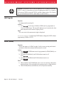
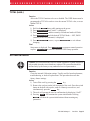
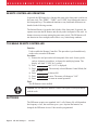
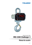
FEATURES
• Designed to meet or exceed US and International Standards.
• Up to 100 hours of weighing time utilizing Automatic Sleep Mode.
• Automatic Power Off conserves battery life by sensing no activity after 12
minutes or one hour, determined by operator, and turns Power off.
• Automatic Sleep Mode preserves battery life by dimming the LED display
after one minute of no activity.
• Rugged construction throughout. Buttons are sealed and rated for over 1
million operations.
• Precise high resolution (2500 division standard and up to 10,000 possible) 20
bit A/D conversion coupled with advanced 16 bit micro controller provides
world class features and accuracy.
• Five large, 1.2 inch LED digits for clear weight readings from a distance.
• Easy to maintain: Full digital calibration assures reliable, repeatable measurements.
• Selectable for kgs/lbs; unless prohibited by regulations.
• Automatic or manual weight totalization for loading operations.
• Easily customized for special applications.
• PEAK Mode for stress analysis.
• Two Set Points can be set for any in-range weight for operator alerts or
process control.
Set Point
Low Battery
Annunciators Warning
1
LO BATT
2
Peak
Hold
Motion Detect
MOTION
PEAK
5 Digit Weight
Indication
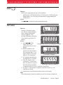
The LED display
provides excellent
readability from full
sunlight to total darkness.
Calibration Screw
Access
0
Center of
Zero
NET
Net
Mode
GROSS
Gross
Mode
TOTAL
Totalizing
X1000
6th Digit
Substitution
Light Emitting Diode Display
Page 6
MSI-3360 Challenger 2
•
User Guide
M E A S U R E M E N T
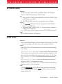
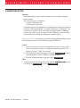
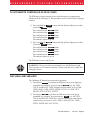
In the event of an
overload condition, the
display will flash a
warning to the operator.
S Y S T E M S
1
0
LO BATT
2
NET
GROSS
PEAK
I N T E R N A T I O N A L
MOTION
TOTAL
X1000
1
0
LO BATT
2
NET
PEAK
MOTION
TOTAL
GROSS
X1000
Overload Display:
Error flashes alternately with LOAd
OPTIONS
Options which you may have ordered with your Challenger 2 may include the
following:
• Infrared Remote Controller.
• 115 or 230 VAC input power.
UNPACKING
When unpacking the scale from the shipping container, ensure that all assembly
parts are accounted for. Check the scale for any visible damage and immediately report any damage to your shipper. It is advisable to use the original
shipping container when shipping or transporting the Challenger 2.
ASSEMBLY
Identify and locate the following (see MSI-3360 assembly parts drawing):
1. Battery pack
2. Cotter pin
3. Load cell
4. Hook clevis assembly
5. Clevis pin
MSI-3360 Challenger 2
•
User Guide
Page 7
M E A S U R E M E N T
S Y S T E M S
I N T E R N A T I O N A L
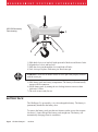
MSI-3360 Assembly
Parts drawing.
1
2
5
3
4
1) Slide hook clevis over load cell with open end of hook toward front of scale.
2) Align holes of clevis and load cell.
3) Slide the clevis pin through the clevis and load cell holes.
4) Lock clevis pin in place with cotter pin. Bend cotter pin.
WARNING: Scale will be unsafe for use if clevis pin is not properly secured
with the cotter pin.
5) Slide battery pack into battery compartment. The battery will automatically
engage with its connectors.
6) Secure battery pack by turning the two locking fasteners on access door
clockwise 1/4 turn.
7) The scale is now ready for use.
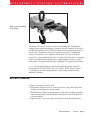
BATTERY PACK
The Challenger 2 is powered by a six volt rechargeable battery. The battery is
permanently attached to the battery door.
To remove the battery pack, turn the two fasteners on the access door counterclockwise 1/4 turn, then pull the battery pack straight out. The battery will
automatically disengage from its connectors.
Page 8
MSI-3360 Challenger 2
•
User Guide
M E A S U R E M E N T
S Y S T E M S
I N T E R N A T I O N A L
Battery pack installation
and removal
The battery will operate for up to 100 hours (depending on LED brightness
setting) before requiring recharging. In order to conserve battery life, the scale
includes an Automatic Power Off Mode which senses operational status for no
activity after 12 minutes or one hour, and turns the scale off. An additional
battery saving feature is the Automatic Sleep Mode. This feature preserves
battery life by dimming the display after 1 minute of no scale activity. Charging
time for a completely discharged battery is approximately 16 hours. A spare
battery pack is recommended to keep the Challenger 2 in continuous operation.
Note: To obtain maximum service life from your batteries they should be
stored between -4°F and 122°F (-20°C and +50°C). Stored batteries should
be recharged every three months. Battery is fully charged when the status
indicator is flashing.
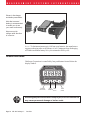
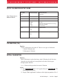
BATTERY CHARGER
1) Remove the battery from the scale.
2) Plug battery charger into an AC power receptacle of the same voltage and
frequency stamped on the plug-in module.
3) Slide the battery charger connector plate over the top of the battery until the
battery terminals mate with the charger connectors, as seen through the two
observation holes.
4) Approximately 16 hours is required to recharge a fully discharged battery.
MSI-3360 Challenger 2
•
User Guide
Page 9
M E A S U R E M E N T
S Y S T E M S
I N T E R N A T I O N A L
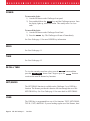
Shown is the charger
and battery assemblies.
Note that a second
battery is recommended
to enable you to use
your scale continuously.
Keep one on the
charger while the other
is in service.
Note: To obtain maximum service life from your batteries, the manufacturer
suggests recharging after each 20 hours of use. Continuous deep discharging
will inhibit maximum battery life cycle estimated at 2000 cycles.
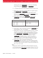
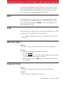
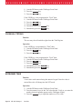
OPERATION GUIDE
Challenger 2 operation is controlled by four push buttons located below the
display window.
Measurement Systems International
2
CHALLENGER
1
0
MODEL 3360
Seattle, Washington U.S.A.
LO BATT
2
NET
PEAK
TOTAL
GROSS
5000 x 2 kg
POWER
POWER
(Decimal Pt.)
MOTION
X1000
10000 x 5 lb.
0
T
ZERO
TARE
ZERO
TARE
(Clear/Exit) (Enter)
USER
USER
(Select)
WARNING
WARNING
Activating the push buttons with a sharp object, such as a screwdriver
may cause permanent damage or broken seals.
Page 10
MSI-3360 Challenger 2
•
User Guide
M E A S U R E M E N T
S Y S T E M S
I N T E R N A T I O N A L
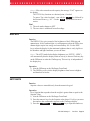
The four push button functions are as follows:
POWER
POWER
Function
Turns the scale on/off (toggle action).
Use
1) The battery pack must have enough charge to ensure accurate operation
(>5.4V).
2) Ambient temperature must be greater than -30°C and less than 60°C
(-22°F to 140°F).
Action
1) Press POWER and hold for one second.
2) Display check: All segment and indicator LED’s are illuminated for one
second.
3) Numerics display the software version number for one second.
4) Any weight on the scale up to 5% of capacity will be automatically
zeroed.
5) During display test, all internal operations are checked and any nonconformance causes an Error message display.
Final
Scale reads the current weight in the last set Mode (NET, GROSS, PEAK
NET, PEAK GROSS).
ZERO
0
ZERO
Function
Sets scale to ZERO.
Use
1) The scale must be stable. The scale will not ZERO if the motion detect
indicator is on.
2) The scale must be in the GROSS Mode. The scale will not ZERO in NET
Mode.
3) The scale will accept a ZERO setting over the full range of the scale
(Legal For Trade models might have a limited ZERO range). ZERO
settings greater than 5% of capacity will subtract from the overall
capacity of the scale.
Action
1) Press ZERO . The weight reading must be stable within ±1 division. If
this condition is met, the digits display "0" (or "0.0" or "0.00", depending
on resolution).
MSI-3360 Challenger 2
•
User Guide
Page 11
M E A S U R E M E N T
S Y S T E M S
I N T E R N A T I O N A L
2) The ZERO setting is stored in backup memory, and the setting will be
restored the next time the scale is turned on.
Final
GROSS indicator is illuminated and display will be "0" (or "0.0" or "0.00",
depending on resolution).
TARE
T
TARE
Function
TARE IN - Stores a TARE weight when in GROSS Mode and displays all
subsequent readings in NET Mode;
or,
TARE OUT - Clears the TARE weight when in NET Mode and returns the
scale to GROSS Mode.
Action
TARE IN
1) Press TARE .
2) The scale must be in GROSS Mode: The entire range of the scale can be
tared.
3) The Motion indicator must be off and the weight reading must be stable.
(The weight reading must be stable within ± 1 division).
4) If the Motion condition is met, the NET indicator lights and the weight
registers "0". All subsequent readings are deviations from the set TARE
value.
5) Only positive weight readings can be tared.
6) Setting or changing TARE has no effect on the ZERO setting.
7) Tareing will reduce the apparent overrange of the scale. For example, if a
1000 lb container is tared and the scale capacity is 5000 lb, the scale
will overload at a new weight of 4000 lb (5000 - 1000) plus any additional allowed overload (usually 9 divisions).
8) TARE value is stored in backup memory, and the value will be restored
the next time the scale is turned on.
TARE OUT
1) The scale must be in NET Mode.
2) Press TARE to clear the value.
3) Returns to GROSS Mode.
Final
TARE IN
TARE is set, displaying NET weight.
TARE OUT
TARE weight will be cleared and the scale will revert to GROSS Mode.
Page 12
MSI-3360 Challenger 2
•
User Guide
M E A S U R E M E N T
USER
S Y S T E M S
I N T E R N A T I O N A L
USER
Function
USER can be programmed to any of five functions:
TEST (tESt), NET/GROSS (nEtGr), TOTAL(totAL), UNIT(kg/lb) and
PEAK(Phold). See Scale Setup for instructions on programming the
USER button.
Action
Press USER to initiate the preprogrammed function.
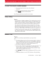
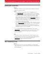
TEST (tESt)
1
2
LO BATT
PEAK
MOTION
Function
Provides a functional system
0
TOTAL
NET
X1000
GROSS
test, and an on-demand display
5000 x 2 kg
10000 x 5 lb.
check without disturbing the
Battery condition in percent remaining . . .
current weighment. Also
MOTION
LO BATT
PEAK
1 2
provides calibration verification
in the form of a load cell CAL
number.
0
TOTAL
NET
X1000
GROSS
Action
5000 x 2 kg
10000 x 5 lb.
1) Press USER (USER
all segments & indicators are displayed for 3 seconds . . .
button must be programmed as test (see Scale
MOTION
LO BATT
PEAK
1 2
Setup)).
2) Battery condition is displayed in Percent of battery
0
TOTAL
NET
X1000
GROSS
life remaining with b = xxx
5000 x 2 kg
10000 x 5 lb.
figure from 0 to 100 on the
CAL number is displayed . . .
digits (in 5% increments).
MOTION
LO BATT
PEAK
1 2
3) All segments and indicators
are displayed for 3 seconds.
4) The CAL number is dis0
TOTAL
NET
X1000
GROSS
played next. To ensure that
5000 x 2 kg
10000 x 5 lb.
the CAL number is accurate
and all digits count once from 0 to 9.
the scale must be unloaded.
Cal number shifts of up to 10 counts are insignificant.
5) All digits (7 segment and 16 segment) count once from 0 to 9. All
indicators are tested.
6) Internal tests are performed to further ensure scale integrity.
Final
The reading returns to the last condition, or an Error message is displayed.
MSI-3360 Challenger 2
•
User Guide
Page 13
M E A S U R E M E N T
S Y S T E M S
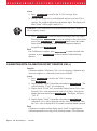
ACCESSING THE SERVICE COUNTERS
I N T E R N A T I O N A L
1
2
LO BATT
PEAK
MOTION
Function
Challenger 2 maintains two service
0
TOTAL
X1000
NET
GROSS
counters for safety, and two service
5000 x 2 kg
10000 x 5 lb.
counters that monitor internal
LCnt1 will be displayed for 1 second followed by . . .
electronics. These Service Counters
MOTION
LO BATT
PEAK
1 2
are used to judge when the load
bearing elements or electronic
components should be inspected.
0
TOTAL
X1000
NET
GROSS
Action
5000 x 2 kg
10000 x 5 lb.
1) To access the Service
a flashing total of "over 25%" weighments.
Counters, program the USER
button to TEST (tESt).
MOTION
LO BATT
PEAK
1 2
2) Press TEST and hold until
the display reads "LCnt1"
(Load Counter #1). This will
0
TOTAL
X1000
NET
GROSS
5000 x 2 kg
10000 x 5 lb.
occur after the RCAL value
has been displayed. "LCnt1" LCnt2 will be displayed for 1 second followed by . . .
will be displayed for 1
MOTION
LO BATT
PEAK
1 2
second, followed by a
flashing numeric value. This
value signifies the number of
0
TOTAL
X1000
NET
GROSS
weighments that exceeded
5000 x 2 kg
10000 x 5 lb.
25% of capacity.
a flashing total of "over capacity" weighments.
3) Press TEST , "LCnt2"
(Load Counter #2) will be
displayed for one second, followed by a flashing numeric value. This
value signifies the number of weighments that surpassed capacity.
4) Press TEST , "A2DEr" (A2D Errors) will be displayed for one second,
followed by a flashing numeric value. This value signifies the number of
times the internal microprocessor has reset the analog to digital converter.
5) Press TEST , "EE Er" (EEPROM Errors) will be displayed for one
second, followed by a flashing numeric value. This value signifies the
number of retries needed to successfully read from or write to the long
term memory module.
6) Press TEST again to complete the TEST sequence.
Final
TEST sequence continues.
Page 14
MSI-3360 Challenger 2
•
User Guide
M E A S U R E M E N T
S Y S T E M S
I N T E R N A T I O N A L
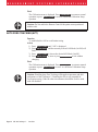
TO RESET THE SERVICE COUNTER WARNING
1) After inspecting the load train, remove the calibration
seal screw.
2) Push the Calibration button using a blunt screwdriver.
3) Push ZERO to return to normal operation
Note: This procedure does not reset the service counter.
TOTAL (TOTAL)
Function
For accumulation of multiple weighments. The accumulator always uses the
displayed weight, so GROSS and NET readings can be added into the same
TOTAL. There are two Modes of totalizing: Manual and Auto. The Manual
Mode requires the TOTAL button be pressed with the weight on the scale.
The weight will be added to the previously accumulated value. The Auto
Mode will automatically add the last settled and stable value to the TOTAL.
Both Modes require that the weight on the scale return within 1% (relative to
full scale) of GROSS ZERO or NET ZERO before the next weighment can
be added. This assures that a weight on the scale is only added to the total
once. Applied weight must be 2% of full scale above GROSS ZERO or NET
ZERO before it can be totaled.
MANUAL TOTAL
Function
Allows for accumulating weight manually by pressing a button.
Use
1) The Motion indicator must be off, the scale must be stable ±1 division. If
there is considerable motion on the scale, use the Medium or High Filter
setting (see Filter Setup). The scale will accept the TOTAL button when
in motion, but will not TOTAL until the Motion indicator is off.
2) Only positive readings can be accumulated.
3) After a weight is totaled, the weight on the scale must return below 1% of
full scale capacity relative to GROSS ZERO or NET ZERO before
another weight can be added to the TOTAL. This assures that a weight
on the scale is only added to the scale once.
4) Press USER (USER button must be programmed as TOTAL (see Scale
Setup).
5) If the Motion indicator is on, the TOTAL indicator will begin blinking,
MSI-3360 Challenger 2
•
User Guide
Page 15
M E A S U R E M E N T
S Y S T E M S
I N T E R N A T I O N A L
and continue blinking, until motion stops and the Motion indicator turns
off. The current weight is added to the TOTAL register and the TOTAL
weight is displayed.
6) The TOTAL indicator (center right of display) will also illuminate for 4
seconds providing reinforcement that the TOTAL command was
accepted.
Final
After totaling, normal weighing resumes.
AUTO TOTAL
Function
Allows for Auto accumulate.
Use
1) When a weight threshold of 2% of Full Scale (FS) above NET ZERO or
GROSS ZERO is exceeded, the accumulate function operates automatically.
2) When a weight that meets the minimum acceptable limit settles (no
Motion), the TOTAL indicator will flash 3 times.
3) If the weight changes to a new settled value the TOTAL indicator will
flash again indicating the previous settled reading has been replaced.
4) When a weight is totaled, the TOTAL indicator will flash for a steady 4
seconds, indicating the weight has been totaled and the TOTAL value
will be displayed.
5) The displayed weight is added to the accumulated value in the TOTAL
Register only when the weight returns to ZERO (±1% of Full Scale ).
6) The last settled reading is what will be used for totalizing when the scale
returns to ZERO.
WARNING: The operator must take caution that, when removing the load,
the scale does not go out of Motion; or an erroneous reading could occur. The
last settled weight is actually added to the TOTAL when the scale returns to
less than 1% of full Scale capacity.
Action
1) The scale cannot be in motion. An Auto TOTAL acceptable reading is
indicated by 3 or more short flashes of the TOTAL indicator.
2) Weight readings must be greater than 2% of full scale, relative to NET
ZERO or GROSS ZERO.
3) Each reading added to TOTAL must be preceded by a return to ZERO
(NET or GROSS) ±1% of full scale. Totalization of the last settled
weight is indicated by a 4 second flash of the TOTAL indicator, and a
Page 16
MSI-3360 Challenger 2
•
User Guide
M E A S U R E M E N T
S Y S T E M S
I N T E R N A T I O N A L
display of the current TOTAL.
Final
After totaling, normal weighing resumes.
TO CLEAR THE LAST TOTALED WEIGHT
Function
If the last totaled (automatic or manual) weighment was a mistake, it can be
erased with the following procedure. This erases only the last totaled value.
Action
1) Press USER , then ENTER(TARE) . The display will read the revised
TOTAL for 2 seconds. (This procedure assumes that you have not
modified the USER function.)
Final
After displaying the update TOTAL, normal weighing resumes.
TO CLEAR THE TOTAL VALUE
Function
To clear the TOTAL register in order to start a new series of totals.
Action
1) Press USER , then CLEAR(ZERO) . (This procedure assumes that you
have not modified the USER function.)
2) The display reads "0" and the TOTAL indicator will illuminate for 2
seconds.
Final
After clearing the TOTAL, normal weighing resumes.
VIEWING TOTAL
Function
After a weight has been totaled or before the 1% threshold has been exceeded, the current TOTAL can be Viewed.
Action
1) Make sure there is no load on the scale. Press USER (USER button
must be programmed as TOTAL).
2) The current TOTAL will be displayed for 3 seconds. The TOTAL
indicator will illuminate.
Final
Normal weighing resumes.
MSI-3360 Challenger 2
•
User Guide
Page 17
M E A S U R E M E N T
S Y S T E M S
I N T E R N A T I O N A L
Caution: If in Manual TOTAL and you push the TOTAL button to view the
TOTAL value, be certain that you are not weighing more than 2% of capacity.
(If you press USER to view the TOTAL and the weight is above 2% of capacity, you will add to the TOTAL, rather than view the TOTAL.)
UNIT (kg/lb)
Function
To change unit between kg/lb.
Action
1) Press USER to select kg or lb Mode (USER must be programmed as
Unit; see USER Setup). The kg and lb indicators are located on the front
panel adjacent to their relative capacity labels.
Final
The correct unit of measurement/weight is displayed.
Alternate Method: Use the Setup UNITS Mode to change the UNITS without
programming USER to UNITS.
PEAK (Phold)
Function
Allows the capture of a PEAK weight. Useful for stress testing and related
operations where the maximum load measured is stored.
Action
1) Press USER (USER button must be programmed as PEAK(Phold); see
USER Setup).
2) To enable PEAK(Phold), the PEAK indicator must be off.
Press USER .
3) To disable PEAK(Phold) the PEAK indicator must be on.
Press USER .
Final
1) When enabled, the PEAK(Phold) value is reset to 0 and any subsequent
displayed value will correspond to the greatest positive weight detected.
2) When PEAK(Phold) is disabled the scale will perform normally.
Page 18
MSI-3360 Challenger 2
•
User Guide
M E A S U R E M E N T
S Y S T E M S
I N T E R N A T I O N A L
NET/GROSS (nEtGr)
Function
Switches the display between NET and GROSS Modes. NET Weight is
defined as GROSS Weight minus a TARE Weight.
Use
1) There must be a TARE weight established to switch from GROSS Mode
to NET Mode (see TARE).
2) NET GROSS(nEtGr) will work even when the scale is in Motion.
Action
1) Press USER (USER button must be programmed as NET GROSS
(nEtGr), see USER Setup).
2) No current TARE is stored (TARE =0). No action, display continues to
read the Gross weight only.
3) A TARE value is stored: Toggles between NET and GROSS indicators.
Final
NET or GROSS indicator will illuminate.
SCALE SETUP
Function
Scale Setup facilitates changes to various internal settings of the scale. Setup
is initiated by holding in the USER button while turning POWER on.
Action
When in SETUP, the following buttons are used for selecting and changing
scale settings:
ZERO functions as CLEAR/EXIT: Used to exit from a Setup menu without
affecting the previous setting and for exiting Setup Mode completely. Used
also to clear the current digit when entering numeric values; i.e., Set Points.
TARE functions as ENTER: Used to enter into menus and choose menu
items.
USER functions as SELECT: Used to scroll through menu selections. If
held down, SELECT will automatically repeat.
POWER functions as Decimal Point: Used for entering a decimal point in
displayed values (i.e. Tare or Setpoint).
Final
Pressing CLEAR(ZERO) will skip all remaining parameters and return the
scale to normal operation. Pressing POWER will also exit the Setup Mode
(and turn Power off).
MSI-3360 Challenger 2
•
User Guide
Page 19
M E A S U R E M E N T
S Y S T E M S
I N T E R N A T I O N A L
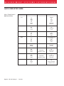
QUICK USER SETUP GUIDE
Note: Display items in
bold are defaults.
Top Menu
Selection Display
Sub-Menu
Func
OFF
tESt
totAl
Unit
Phold
nEtGr
Function
Off
Test
Total
Unit
Peak Hold
Net/Gross
OFF
.2 hr
1 hour
Automatic Power Off
Off
12 minutes
1 hour
LO
HI-1
HI-2
Filter
Low
Medium
High
Auto
LO
HI-1
HI-2
Light Emitting Diodes
Automatic
Low
Medium
High
Unit(kg)
Unit(lb)
Units
Kilograms
Pounds
OFF
GrEAt
LESS
LESS,GrEAt
followed by value
Set Point 1
Off
Greater than
Less Than
LESS,GrEAt
followed by value
Set Point 2
Off
Greater Than
Less Than
A-OFF
Filtr
LEdS
Unit
StPt1
StPt2
OFF
GrEAt
LESS
totAL
Page 20
MSI-3360 Challenger 2
•
User Guide
Display Definition
OFF
PrESS
Total
Off
Press User Button
Auto
Automatic Total
M E A S U R E M E N T
S Y S T E M S
I N T E R N A T I O N A L
FUNCTION (Func)
Function
Allows the USER button to be programmed to TEST, TOTAL, UNIT, NET/
GROSS or PEAK
Action
1) Hold in the USER button while turning on the power.
2) Press SELECT(USER) until the display reads "Func".
3) Press ENTER(TARE) and currently selected function will flash.
4) Press SELECT(USER) until desired function is displayed.
5) Press ENTER(TARE) to store or press CLEAR(ZERO) to exit without
changing.
Final
Setup menu is displayed. Press CLEAR(ZERO) to return to normal operation
or press SELECT(USER) to scroll to a different USER Setup operation.
AUTOMATIC POWER OFF (A-OFF)
Function
The A-OFF feature, when enabled, prolongs the battery life of the scale by
turning POWER off when the scale is not in use. Any time a button is
depressed (any button), or the detected weight is in Motion, the time limit is
reset. Therefore, the scale will stay on indefinitely if the weight is changing
or any button is pressed at least once. With A-OFF disabled, the scale will
remain on; only pressing POWER will turn it off.
Action
To Change the A-OFF Mode:
1) Hold in the USER button while turning on the power.
2) Press SELECT(USER) until the display reads "A-OFF".
3) Press ENTER(TARE) . You are now in the A-OFF menu.
4) Press SELECT(USER) to choose: OFF, .2 hours (12 minutes), or 1 hour.
When the desired Mode is displayed, press ENTER(TARE) or press
CLEAR(ZERO) to exit without changing.
Final
USER Setup menu is displayed. Press CLEAR(ZERO) to return to normal
operation or press SELECT(USER) to scroll to a different USER Setup operation.
MSI-3360 Challenger 2
•
User Guide
Page 21
M E A S U R E M E N T
S Y S T E M S
I N T E R N A T I O N A L
FILTER (Filtr)
Function
Allows three levels of filtering to stabilize readability of the weight display.
Use
1) Use LO (low setting), for most scale applications. It settles fastest and is
intended for general use.
2) Use HI-1 (medium setting), when the scale is being used under conditions that cause light to medium swinging.
3) Use HI-2 (high setting), when there is significant scale motion. There is a
time penalty when using the HI-2 setting. The operator should wait at
least 5-15 seconds to ensure that the final reading has settled (motion
indicator off). (Not available in some Legal For Trade scales).
Action
To change the Filter settings:
1) Hold in the USER button while turning on the power.
2) Press SELECT(USER) until the message reads "Filtr".
3) Press ENTER(TARE) . The currently selected filter will flash.
4) Press SELECT(USER) to change from LO (low), HI-1(medium) or HI-2
(high) settings. When the desired Filter setting is displayed on the
message display, press ENTER(TARE) or press CLEAR(ZERO) to exit
without changing the setting.
Final
Setup menu is displayed. Press CLEAR(ZERO) to return to normal operation
or press SELECT(USER) to scroll to a different USER Setup operation.
LED BRIGHTNESS (LEdS)
Function
Sets the LED brightness to one of three fixed settings; or to an automatic
setting that adjusts brightness according to ambient light, and also adjusts to
the lowest level of brightness when the scale is inactive for 1 minute (Automatic Sleep Mode). Automatic Sleep Mode is recommended for minimizing
battery consumption.
Action
1) Hold in the USER button while turning on the power.
2) Press SELECT(USER) until "LEdS" is displayed.
3) Press ENTER(TARE) and currently selected brightness will flash.
4) Press SELECT(USER) to change from AUTO, LO, HI-1 or HI-2 settings.
5) Press ENTER(TARE) to store, or press CLEAR(ZERO) to exit without
Page 22
MSI-3360 Challenger 2
•
User Guide
M E A S U R E M E N T
S Y S T E M S
I N T E R N A T I O N A L
changing.
Final
Setup menu is displayed. Press CLEAR(ZERO) to return to normal operation
or press SELECT(USER) to scroll to a different USER Setup operation.
Note: To maximize battery life, set the LED to the Automatic Sleep Mode.
UNIT (kg/lb)
Function
Allows Units to alternate between kg and lb without the use of the USER
button.
Action
1) Hold in the USER button while turning on the power.
2) Press SELECT(USER) until "Unit" is displayed.
3) Press ENTER(TARE) . The display will show "Unit" while the indicator
which correlates to the currently set Unit (kg or lb) will flash.
4) Press SELECT(USER) until desired Unit (kg or lb) is displayed.
5) Press ENTER(TARE) to store, or press CLEAR(ZERO) to exit without
changing.
Final
Setup menu is displayed. Press CLEAR(ZERO) to return to normal operation
or press SELECT(USER) to scroll to a different USER Setup operation.
Alternate Method: Program the USER button as UNITS.
SETPOINTS (StPt1, StPt2)
Function
Set Points provide warnings and indications of weighments. When the weight
is above (greater than) or below (less than) a set value, the Challenger 2 can
respond by turning on the Set Point indicator light.
SET POINT ENTRY
Function
To enter a Set Point.
Action
1) Hold in the USER button while turning on the power.
MSI-3360 Challenger 2
•
User Guide
Page 23
M E A S U R E M E N T
S Y S T E M S
I N T E R N A T I O N A L
2) Press SELECT(USER) to choose the Set Point you wish programmed. Set
Point 1 will be used for this example.
3) When the display reads "StPt1" press ENTER(TARE) .
4) Determine if the Set Point will be active when the weight is above
("GrEAt") or below ("LESS") the entered value. Press SELECT(USER) to
choose the mode. For an overload alarm, for example, you would choose
greater. Press ENTER(TARE) .
5) The current Set Point value will flash.
6) Press SELECT(USER) to enter the first digit of the desired Set Point
weight value (Value cannot exceed scale capacity). Press ENTER(TARE) .
Note: Press POWER to enter a decimal point.
7) The next significant digit flashes. Press SELECT(USER) to enter the next
digit. Press ENTER(TARE) twice after the last character to complete the
Set Point entry.
Final
Setup menu is displayed. Press CLEAR(ZERO) to return to normal operation
or press SELECT(USER) to scroll to a different USER Setup operation.
TO DISABLE A SET POINT
Function
To turn off a Set Point.
Action
1) Hold in the USER button while turning on the power.
2) Press SELECT(USER) to identify the Set Point you wish to disable. Set
Point 1 will be used for this example.
3) When the display reads "StPt1" press ENTER(TARE) .
4) Press SELECT(USER) until the message "OFF" appears.
Press ENTER(TARE) . This disables the Set Point and returns you to the
Set Point menu.
Final
Setup menu is displayed. Press CLEAR(ZERO) to return to normal operation
or press SELECT(USER) to scroll to a different USER Setup operation.
Page 24
MSI-3360 Challenger 2
•
User Guide
M E A S U R E M E N T
S Y S T E M S
I N T E R N A T I O N A L
TOTAL (totAL)
Function
Allows the TOTAL function to be set or disabled. The USER button must be
programmed to TOTAL in order to view the current TOTAL value, or to use
Manual TOTAL.
Action
1) Hold in the USER button while turning on the power.
2) Press SELECT(USER) until "totAL" is displayed.
3) Press ENTER(TARE) and the currently selected total mode will flash.
4) Press SELECT(USER) until the desired TOTAL Mode — OFF, PrESS
(manual), or AUTO (automatic) is displayed.
5) Press ENTER(TARE) to store, or press CLEAR(ZERO) to exit without
changing.
Final
Setup menu is displayed. Press CLEAR(ZERO) to return to normal operation
or press SELECT(USER) to scroll to a different USER Setup operation.
SYSTEM INITIALIZE
Caution: Do Not Initialize the scale for routine calibration. System initialize is
only needed when the circuit boards are replaced. This procedure should be
initiated only by the factory or any authorized service representative.
Function
Clears the internal Calibration settings. Usually used for board replacement,
troubleshooting, or load cell replacement. This procedure does not alter
factory feature settings.
Action
1) Turn off the scale by pressing the POWER key.
2) Remove the seal port on the left front panel of the scale. Press the switch
button in the hole with a probe, such as a blunt tip screwdriver, and
simultaneously press the POWER key.
3) The scale will prompt the user for confirmation by displaying “SurE?”
4) Pressing TARE will continue the system initialization. Pressing
ZERO will abort the system initialization without resetting any
parameters.
MSI-3360 Challenger 2
•
User Guide
Page 25
M E A S U R E M E N T
S Y S T E M S
I N T E R N A T I O N A L
CALIBRATION SETUP
Function
Calibration Setup is used to initiate calibration or to set seldom changed
factory settings.
There are two types of calibration:
1) Initial Calibration; and
2) Subsequent Calibration
Calibration must be accomplished by a qualified Scale Technician trained in
Certified Calibration Standards. To initiate calibration of a Challenger 2, the
Technician is required to have an accurate test weight system of adequate
capacity and, in the case of a Legal For Trade Challenger 2, the test weight
system must be certified by the appropriate regulatory agency.
Important Note: At any point (except when entering calibration weight values),
the calibration procedure can be halted by turning POWER off.
Action
1) Remove the seal port on the left front panel of the scale. Insert a probe,
such as a blunt tip screwdriver, to depress the underlying button. The
display will show "C-SEt" for 1 second.
2) The Calibration Setup Menu appears. Press the SELECT(USER) button to
scroll through the various Calibration Setup menu choices.
3) Once the desired operation is displayed, press ENTER(TARE) .
Final
To return to normal operation either scroll with the SELECT(USER) button to
exit and press ENTER(TARE) , or press CLEAR(ZERO) .
Page 26
MSI-3360 Challenger 2
•
User Guide
M E A S U R E M E N T
S Y S T E M S
I N T E R N A T I O N A L
QUICK CALIBRATION SETUP GUIDE
Top Menu
Note: Display items in
bold are defaults.
Selection Display
Display Definition
CAL
Calibration
F-CAL
Fine Calibration
CAL-r
Calibration with Offset Calibration Resistor
StAnd
IndUS
nISt
EuroP
1 Unit
r-Ctl
Standards
Industry
National Institute of Standards & Technology
Metric (kg only)/OIML
One Unit Only
Remote Control
On
OFF
AZt
Automatic ZERO Tracking
On
Off
CALIBRATION (CAL)
Function
Used to Calibrate the scale load cell. There are two types of calibration:
1) Initial Calibration and
2) Subsequent Calibration.
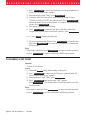
INITIAL CALIBRATION
Function
Initial Calibration is used at the factory when Calibrating for the first time,
when the circuit boards have been replaced or after the scale has gone
through System Initialize.
Note: Do not use this procedure for routine Calibration.
Action
1) Press SELECT(USER) until "CAL" appears then press ENTER(TARE) . The
following steps will occur:
2) Display flashes right hand lb. indicator while displaying number of lbs. if
MSI-3360 Challenger 2
•
User Guide
Page 27
M E A S U R E M E N T
S Y S T E M S
I N T E R N A T I O N A L
calibrating in lbs. press ENTER(TARE) , or to select kgs (left hand kg
indicator flashes) press SELECT(USER) then ENTER(TARE) .
Note: This step will not occur in scales equipped to measure in only one unit.
3) Display shows "CAP" for 2 seconds then flashes "0". Input the capacity
using SELECT(USER) and ENTER(TARE) .
4) Display shows "d" for 2 seconds, then flashes the default Count By
(division). Press ENTER(TARE) to accept, or press SELECT(USER) to pick
another Count By, then press ENTER(TARE) .
5) Display flashes "GAin4". Press ENTER(TARE) to accept, or press
SELECT(USER) to pick another gain, then press ENTER(TARE) .
See Gain Table.
Capacity of Scale
Gain
250 lb
500 lb
1,000 lb
125 kg
250 kg
500 kg
4
3
4
2,000 lb
1,000 kg
3
Capacity of Scale
5,000 lb
10,000 lb
15,000 lb
2,500 kg
5,000 kg
7,500 kg
Gain
4
3
3
Gain Table
6) Display flashes "UnLd". Unload the scale and press ENTER(TARE) . The
scale will display "CALC", for calculating.
7) Display shows "LOAd" for 2 seconds then flashes the capacity. Load the
scale with a test weight that is equal to capacity weight; or if the test
weight is less than capacity, enter the actual weight of the test weight by
pressing SELECT(USER) then ENTER(TARE) . After the last number of
the weight has been entered and the motion indicator is off press
ENTER(TARE) . The display will show "CAL’d" if successful, or
"CErr" if not successful. An unsuccessful calibration can be due to an
improper gain setting, or use of a calibration weight that is too light.
8) Display flashes "UnLd". Unload the scale and press the
ENTER(TARE) button. Afterwards "r-CAL" will be displayed until the
value is determined. If successful, then the CAL-r value is displayed for
10 seconds or until any button is pressed. If unsuccessful, the display will
show "r-Err" for 2 seconds.
Final
Display shows "StorE" to signify that the calibration parameters are being
saved in backup memory. When complete the display will show "F-CAL" for
the next menu item. Press CLEAR(ZERO) to return to normal scale operation.
Page 28
MSI-3360 Challenger 2
•
User Guide
M E A S U R E M E N T
S Y S T E M S
I N T E R N A T I O N A L
SUBSEQUENT CALIBRATION
Function
Subsequent Calibration is used for routine annual Calibration or when the
scale is not weighing accurately.
Action
1) To set ZERO the display flashes "UnLd". Unload the scale and
press ENTER(TARE) . The scale will display "CALC" (for calculating).
2) To input the Calibration weight value the display will show "LOAd" for
2 seconds then flash the capacity. Load the scale with this weight or
input another weight. After the last number of the weight has been
entered and the motion indicator is off, press ENTER(TARE) . The display
will show "CAL’d" if successful, or "CErr" if not successful. An
unsuccessful calibration can be due to an improper gain setting, or use
of a calibration weight that is too light.
3) To set the CAL-r value the display flashes "UnLd". Unload the scale and
press the ENTER(TARE) button. Afterwards "CAL-r" will be displayed
until the value is determined. If successful, then the CAL-r value is
displayed for 10 seconds or until any button is pressed. If unsuccessful,
the display will show "r-Err" for 2 seconds.
Note: It may be desirable to bypass a calibration step. To do so press
CLEAR(ZERO) . The step bypassed will retain the default or last set value.
However, bypassing a calibration step may result in an incomplete or
inaccurate calibration.
Final
Calibration is complete and the display shows "StorE" to signify that the
calibration parameters are being saved in backup memory. When complete
the display will show "F-CAL" for the next menu item. Press
CLEAR(ZERO) to return to normal scale operation.
FINE CALIBRATION (F-CAL)
Function
Fine Calibration (F-CAL) is for minor adjustments to calibration and is
usually not necessary. It is useful, however, in hydraulic calibration fixtures
for fine adjustments.
MSI-3360 Challenger 2
•
User Guide
Page 29
M E A S U R E M E N T
Action
1) Press
S Y S T E M S
I N T E R N A T I O N A L
to scroll to the "F-CAL" message. Press
.
2) Pick up a test weight of (or set the hydraulic tension to) at least 25% of
capacity. The weight is indicated on the numeric digits. The display will
flash "LOAd" if the weight is under 25%.
SELECT(USER)
ENTER(TARE)
WARNING: Fine Calibration will not function unless the scale is loaded at
25% of capacity or more.
3) Press SELECT(USER) to cause the displayed reading to move up slightly.
Press the button CLEAR(ZERO) to cause the reading to move down. Each
press of the SELECT(USER) or CLEAR(ZERO) button causes the calibration to shift by 1/4 displayed count. When the displayed reading is
acceptable, press ENTER(TARE) .
Final
Fine Calibration is complete, press CLEAR(ZERO) to return to normal scale
operation, or press SELECT(USER) to choose another Calibration Setup
function.
CALIBRATION WITH CALIBRATION OFFSET RESISTOR (CAL-r)
Function
Calibration with the Cal Resistor (CAL-r) is for emergency calibration only
when test weights or a calibration system are not available.
Action
1) Press SELECT(USER) to scroll to the "CAL-r" message.
Press ENTER(TARE) .
2) Display flashes "UnLd". Unload the scale and press ENTER(TARE) . The
scale will display "CALC" (for calculating).
3) Display shows "LOAd" for 2 seconds then flashes last set CAL-r value.
Input the CAL-r value printed on the load cell Cal Sheet. After the last
number has been entered, press ENTER(TARE) . The display will show
"CAL’d".
4) Display flashes "UnLd". Unload the scale and press ENTER(TARE) .
Afterwards CAL-r will be displayed until the value is determined. Then
the CAL-r value is displayed for 10 seconds, or until any button is pressed.
Final
Calibration is complete and the display shows "StorE" to signify that the
calibration parameters are being saved in backup memory. The calibration
Page 30
MSI-3360 Challenger 2
•
User Guide
M E A S U R E M E N T
S Y S T E M S
I N T E R N A T I O N A L
menu returns. Press CLEAR(ZERO) to return to normal operation or press
SELECT(USER) to scroll to a different Calibration Setup operation.
Note: When Calibration is finished, seal the Calibration Port on the front
panel of the scale.
STANDARDS (StAnd)
Function
Facilitates calibration to your required standard:
IndUS
Industrial
nISt
National Institute of Science and Technology (NTEP setting)
EuroP
Metric/OIML
1Unit
One Unit only (for custom scales)
Action
1) Press SELECT(USER) until "StAnd" is displayed.
2) Press ENTER(TARE) and the currently selected standard will flash.
3) Press SELECT(USER) to choose desired standard.
4) Press ENTER(TARE) to store, or press CLEAR(ZERO) to exit without
changing.
Final
The calibration menu is displayed. Press CLEAR(ZERO) to return to normal
operation or press SELECT(USER) to scroll to a different Calibration Setup
operation.
REMOTE CONTROL (r-Ctl)
Function
Used to enable or disable the use of a Remote Control.
Action
1) Press SELECT(USER) until "r-Ctl" is displayed.
2) Press ENTER(TARE) and currently selected Remote Control Mode (On/
Off) will flash.
3) Press SELECT(USER) to choose ON or OFF.
4) Press ENTER(TARE) to store or press CLEAR(ZERO) to exit without
changing.
MSI-3360 Challenger 2
•
User Guide
Page 31
M E A S U R E M E N T
S Y S T E M S
I N T E R N A T I O N A L
Final
The Calibration menu is displayed. Press CLEAR(ZERO) to return to normal
operation or press SELECT(USER) to scroll to a different Calibration Setup
operation.
Caution: Do Not enable the Remote Control if the option was not purchased
with the scale.
AUTO ZERO TRACKING (AZT)
Function
To enable/disable AZt for certification testing.
Action
1) Press SELECT(USER) until "AZt" is displayed.
2) Press ENTER(TARE) and the currently selected AZt Mode (On/Off) will
flash.
3) Press SELECT(USER) to choose the desired AZt Mode (On/Off).
4) Press ENTER(TARE) to store or press CLEAR(ZERO) to exit without
changing.
Final
The Calibration menu is displayed. Press CLEAR(ZERO) to return to normal
operation or press SELECT(USER) to scroll to a different Calibration Setup
operation.
Caution: Disabling Auto Zero Tracking will degrade temperature and drift
performance of the Challenger 2. Disabling the AZt is only intended for
certification testing. Under no other circumstances should the Scale be used
with AZt disabled.
Page 32
MSI-3360 Challenger 2
•
User Guide
M E A S U R E M E N T
S Y S T E M S
I N T E R N A T I O N A L
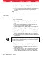
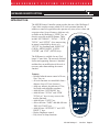
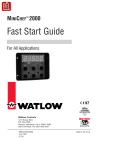
INFRARED REMOTE OPTION
INTRODUCTION
The MSI IR Remote Controller option provides the user of the Challenger 2
Crane Scale complete remote control of all scale operation functions. In
addition, a numeric keypad allows the operator easy entry of tare values and
set-point values. Several features, which are only
available on the Challenger’s “USER” key, are
directly accessible on the IR Remote. These
CODE
PWR
include “NET/GROSS”, “TOTAL”, “VIEW
TOTAL”, and “SETUP”. Also, maneuvering
in menus is simplified by the use of a
SCALE 2ND
“SETUP” key combined with “MENU UP”
(USER), “MENU DOWN” (UNITS),
USER
ZERO TARE
“ENTER”, and “EXIT” (SETUP) keys.
RCL
TARE
The IR Remote is available for any Challenger 2 Crane Scale. The necessary Infrared
Sensor and supporting firmware is standard
and therefore no modification of the scale is
necessary other than enabling the remote
function.
Features:
• Reliable Infrared remote control of Power,
Zero, Tare, etc.
• All scale functions are controllable from a
distance of up to 25 feet (8 meters).
• Adds easy numeric keypad entry of Tare,
Set-Points, and calibration constants.
• Adds full time “NET/GROSS” key.
• Adds full time “TOTAL” and “VIEW
TOTAL (∑)” keys for easy access to the
totalize functions.
• Adds full time “UNITS” key.
• Allows full time “TARE” and adds full time
“RECALL TARE” keys.
• Adds full time “SETPOINT 1” and “SETPOINT 2” keys.
• Display Brightness control.
• Easy access to Setup functions.
UNITS
CLR
ENTER
TOTAL
VIEW
TOTAL
1
ABC
DEF
2
4
JKL
5 MNO
6 PQR
7
STU
8 VWX
9 @YZ
3
GHI
0 SPACE DISPALPHA
NET
GROSS PRINT
ID#
INSERT
SETUP SETPT1 SETPT2
EXIT
MSI-3360 Challenger 2
SETPOINT FUNCTION
Measurement Systems
International
P/N 501546
•
User Guide
Page 33
M E A S U R E M E N T
S Y S T E M S
I N T E R N A T I O N A L
REMOTE CONTROLLER OPERATION
In general, the IR Remote keys function the same as the front panel switches on
the crane scale. The “ZERO”, “TARE”, and “USER” keys function the same as
the front panel keys. The enhanced functions or any functional differences are
detailed in the following sections.
The Infrared Sensor is located to the left side of the front panel. In general, the
operator must aim the IR Remote unit directly at the front panel of the scale. As
distance increases accurate aiming becomes more critical. The IR Remote will
not function in direct sunlight, and will have very limited range outdoors.
TO ENABLE REMOTE CONTROLLER
Function
Used to enable the Remote Controller. This procedure is performed directly
on the scale, not on the IR Remote.
Procedure
1) Remove the seal port on the left front panel of the scale. Insert a probe,
such as a blunt tip screwdriver, to depress the underlying button. The
display will show "C-SEt" for 1 second.
2) Press SELECT(USER) until "r-Ctl" is displayed.
3) Press ENTER(TARE) . The currently selected Remote Control Mode (On/
Off) will flash.
4) Press SELECT(USER) to choose ON.
5) Press ENTER(TARE) to store. The menu will change to "AZt".
6) Press CLEAR(ZERO) to return to normal operation.
Final
The IR Remote is now enabled.
Caution: Do Not enable the Remote Control if the option was not purchased
with the scale.
BATTERIES
The IR Remote requires two standard ‘AAA’ cells. Battery life will depend on
the frequency of use, but could last up to a year. Anytime the batteries are
changed, the IR Remote Access Codes must be programmed.
Page 34
MSI-3360 Challenger 2
•
User Guide
M E A S U R E M E N T
S Y S T E M S
I N T E R N A T I O N A L
TO SET REMOTE CONTROLLER ACCESS CODES
The IR Remote contains internal access codes that must be programmed to
function with the Challenger 2. This procedure must be followed after changing
batteries:
1) Press and hold the CODE button until the indicator light goes on, then
release the CODE button.
Press and release the 2ND button.
1
Press and release the
button.
Press and release the
button.
4
8
Press and release the
button.
The indicator light will go out.
2) Press and hold the CODE button until the indicator light goes on, then
release the CODE button.
Press and release the SCALE button.
Press and release the
button.
0
Press and release the
button.
0
Press and release the
button.
9
The indicator light will go out.
The IR Remote is now ready for use.
WARNING: If the access codes are not properly set, the IR Remote might
fail to function or will function erratically. Always reset the access codes after
changing batteries.
THE SCALE AND 2ND KEYS
The Challenger IR Remote has two modes of operation.
1) Pressing the SCALE key defines the IR Remote keys to the light grey
commands. For example, after pressing the SCALE key, the VIEW
TOTAL and RECALL TARE functions are unavailable. Active: PWR,
USER, ZERO, TARE, UNITS, ENTER, TOTAL, 0-9, DISP, NET/
GROSS, SETUP, SETPT1, SETPT2.
2) Pressing the 2ND key defines the IR Remote keys to the green
commands. For example, after pressing the 2ND key, the VIEW
TOTAL and RECALL TARE keys are active while many other remote
controller keys are inactive. Active: PWR, USER, RECALL TARE,
UNITS, ENTER, RECALL TOTAL.
MSI-3360 Challenger 2
•
User Guide
Page 35
M E A S U R E M E N T
S Y S T E M S
I N T E R N A T I O N A L
POWER
To turn on the Scale:
1) Aim the IR Remote at the Challenger front panel.
2) Press and hold down the POWER key until the Challenger turns on. Once
the display lights up, release the button. This usually takes 2 to 4 seconds.
To turn off the Scale:
1) Aim the IR Remote at the Challenger Front Panel.
2) Press the POWER key. The Challenger will turn off immediately.
See User Guide page 11 for more POWER key information.
ZERO
See User Guide page 11.
TARE
See User Guide page 12.
RECALL TARE
To view the currently stored tare value, press the 2ND button and then
press the RCL TARE
button. Don’t forget to press the SCALE button to
reactivate the main IR Remote key functions.
NET/GROSS
The NET/GROSS function is available on the Challenger 2 as a USER key
function. The Remote provides this function full time through the use of the
NET/GROSS key. See User Guide page 19 for more detail on NET/GROSS.
USER
The USER key is programmable to any of five functions: TEST, NET/GROSS,
TOTAL, UNIT, and PEAK. If you are making regular use of the Remote, there
Page 36
MSI-3360 Challenger 2
•
User Guide
M E A S U R E M E N T
S Y S T E M S
I N T E R N A T I O N A L
is no need to set the USER key to NET/GROSS, UNITS or TOTAL, as these
keys are available full time on the Remote unit. However, there is no harm in
having duplicated functions on the USER key if you so desire. See “Scale
Setup” for instructions on programming the USER button.
UNITS
The UNITS function is available at power up or by programming the USER
key to change between pounds and kilograms. The IR Remote provides this
function full time by pressing the UNITS key. See User Guide page 23 for
more information on UNITS.
TOTAL
The Total function is available full time on the Remote rather than just a USER
key function. See User Guide page 15 for more details.
Note: When the Challenger 2 is set up for AUTO total, the TOTAL key has
no function.
VIEW TOTAL (VIEW ∑)
Function
The VIEW ∑ key gives the user immediate access to the Total Register.
Operation
1) Aim the IR Remote at the Challenger Front Panel.
2) Press the 2ND key.
3) Press the VIEWΣ key. The TOTAL LED will light, and the Total weight
will appear on the numeric digits for 4 seconds.
4) Don’t forget to press the SCALE key to reactivate the main IR Remote
key functions.
CLEAR LAST TOTAL
Function
The user may clear the last totaled weight from the Total Register.
Operation
If the USER key is programmed to “Total” then:
MSI-3360 Challenger 2
•
User Guide
Page 37
M E A S U R E M E N T
S Y S T E M S
I N T E R N A T I O N A L
1) Aim the IR Remote at the Challenger Front Panel.
2) Press the USER key.
3) Press the TARE key.
If the USER key is not programmed to “Total” then:
1) Aim the IR Remote at the Challenger Front Panel.
2) Press the 2ND key.
3) Press the TOTAL key.
4) Immediately press the SCALE key.
5) Immediately press the TARE key.
CLEAR ALL TOTALS
Function
The user may clear all totaled weights from the Total Register.
Operation
If the USER key is programmed to “Total” then:
1) Aim the IR Remote at the Challenger Front Panel.
2) Press the USER key.
3) Press the ZERO key.
If the USER key is not programmed to “Total” then:
1) Aim the IR Remote at the Challenger Front Panel.
2) Press the 2ND key.
3) Press the TOTAL key.
4) Immediately press the SCALE key.
5) Immediately press the ZERO key.
KEYBOARD TARE
Function
A tare value can be entered using the numeric keypad. Once the value is
entered the scale will change into the NET mode.
Operation
1) Aim the IR Remote at the Challenger Front Panel.
2) Press the numeric keys for the Tare value desired. Verify as you enter the
number, that each number appears on the Challenger display.
3) Press the TARE key to input the number as a Tare value.
Page 38
MSI-3360 Challenger 2
•
User Guide
M E A S U R E M E N T
S Y S T E M S
I N T E R N A T I O N A L
Note: If the value entered exceeds capacity the message “2 biG” appears on
the display.
The TOTAL key functions as a decimal point, if needed.
key followed by
To enter a Tare value less than 1, start with the
0
the Decimal Point. e.g. “0.5”. Use the CLR key to delete incorrect
entries.
Final
1) The scale mode changes to NET.
2) The tare value is subtracted from all readings.
DISP KEY
Function
The DISPLAY key gives control of the brightness of the LED digits and
annunciators. In low ambient light, it is advantageous to dim the LEDs since
dimmer digits require less energy and extend battery life. Use the DISP
key to adjust the display for the minimum brightness that is easily legible at
the distances and light conditions you use the most.
Note: The AUTO mode for the display brightness (see “SETUP – LEDS”)
will automatically dim the display when no activity is detected. Push any key
on the IR Remote to wake the Challenger up. This activity is independent of
the display key.
Operation
1) Aim the IR Remote at the Challenger Front Panel.
2) The DISP key will cycle the display brightness from lowest to highest
and then back to lowest.
SETPOINTS
Function
Setpoint values are entered directly from the numeric keypad.
Operation
For a Setpoint that responds when the weight is greater than or equal to the
Setpoint Value:
1) Aim the IR Remote at the Challenger Front Panel.
2) Press the numeric keys for the Setpoint value desired. Verify as you enter
the number, that each number appears on the Challenger display.
SETPT2
3) Press the
or
key to input the number as
SETPT1
MSI-3360 Challenger 2
•
User Guide
Page 39
M E A S U R E M E N T
S Y S T E M S
I N T E R N A T I O N A L
a Setpoint value. The message “StPt 1” or “StPt 2” appears for 2 seconds
verifying the scale has stored the setpoint value in memory.
For a Setpoint that responds when the weight is less than or equal to the
Setpoint Value:
1) Aim the Remote controller at the Challenger Front Panel.
2) Press the numeric keys for the Setpoint value desired. Verify as you enter
the number, that each number appears on the display.
or
key to input the number as
3) Press the
SETPT2
SETPT1
a Setpoint value.
4) While the message “StPt 1” or “StPt 2” appears, immediately push the
ID#
key. The display will change from “StPt 1” to “LESS” indicating that the setpoint is now set to respond when the weight is less than
the value you put in.
Note: If the value entered exceeds capacity the message “2 biG” appears on
the display.
The TOTAL key functions as a decimal point, if needed.
To enter a Setpoint value less than 1, start with the
key fol0
lowed by the Decimal Point. e.g. “0.5”. Use the CLR key to delete
incorrect entries.
ID #
Not supported by the Challenger 2 at this time.
PRINT
Not supported by the Challenger 2 at this time.
SETUP
Function
Setup functions are the same as when accessed by the Challenger Front panel.
The keys used for entering and maneuvering through menus are simplified with
the IR Remote. For a detailed description of the Setup functions, see Scale
Setup, page 19 of this manual.
To Enable the Setup Menus
1) Aim the IR Remote at the Challenger Front Panel.
Page 40
MSI-3360 Challenger 2
•
User Guide
M E A S U R E M E N T
S Y S T E M S
I N T E R N A T I O N A L
2) Press the SETUP key twice. The first menu “Func” (User Key function)
will appear.
Key Functions While In Setup Menus
USER
Use these keys to scroll through the various menus, and to scroll
or UNITS: through the menu selections once in a menu.
ENTER:
CLR
or EXIT:
The ENTER key is used to enter into menus, and to store the
selection in memory once in a menu.
The CLR or EXIT keys are used to exit from menus
without changing the previously selected item. When in the top
level of the Setup Menu, use the CLR key to return to normal
scale operation.
Note: The Challenger 2 can also be controlled by the IR Remote during
calibration. It is still necessary to enable calibration through the seal port, but
from that point on, the Menu, Enter, Numeric, and Clr keys all simplify the
calibration process.
MSI-3360 Challenger 2
•
User Guide
Page 41
M E A S U R E M E N T
S Y S T E M S
I N T E R N A T I O N A L
TROUBLESHOOTING GUIDE
Problem
Possible Cause
1. Display is blank
when POWER button is
depressed
A)
B)
C)
D)
2. Display does not function
properly
or
front panel buttons do not
function normally
or
scale will not turn off
Discharged battery
Defective battery
Corroded battery
Defective button or
electronic circuit board
E) Power button not
properly depressed
Recharge
Replace
Clean connections
Requires authorized service
A) Computer lock-up
Remove and re-insert battery. If problem
persists, authorized service is required
Requires authorized service
B) Faulty electronic circuit
board
C) Faulty front button assembly
3. Display does not
respond to weight changes
4. Display over-ranges
below 100% of capacity
Solution
Press POWER firmly and hold until
Power turns on.
Requires authorized service
A) Same as 2A, B above
B) Out of calibration
C) Faulty load cell or
electronic circuit board
D) Load cell disconnected
from printed circuit board
See 2A, B above
Check calibration
Requires authorized service
A) Tared out weight
is added to load when
overload condition is
determined
B) Zero requires
adjustment
C) Out of Zero range
Normal (See Operation Guide)
Plug in
Recalibrate
Remove dead load and re-zero
5. Display experiences
excessive Zero drift
between weighments
A) AZt turned off
B) Scale electronics do not
stabilize after turning on
(probably due to rapid temperature change)
Go into Cal menu and turn AZt on
Warm up scale for 5 minutes then
re-Zero
6. Display shows large number
after Power-up sequence
with AZt feature Off, and no
applied weight
A) ZERO requires adjustment
B) Defective load cell or
electronic circuit board
Follow Calibration Section
Requires authorized service
7. Displayed weight
shows large error
A) Scale not Zeroed before
applying weight
B) Requires recalibration
C) lb/kg in wrong selection
Depress ZERO before applying weight
Page 42
MSI-3360 Challenger 2
•
User Guide
See Calibration
Set to correct selection
M E A S U R E M E N T
Problem
S Y S T E M S
Possible Cause
I N T E R N A T I O N A L
Solution
8. Display reading not stable
A) Filter set too low
B) Faulty electronic circuit
board
Change filter setting
Requires authorized service
9. Battery charger
indicator does not come
on when discharged
battery is inserted
A) Corroded battery
connections
B) Defective charger
C) Defective battery
Clean connections
Requires authorized service
Replace
10. Display is "LCnt1"
and/or "LCnt2" at
Power on
A) Service Counter exceeded
Inspect load train; and contact factory
11. Display toggles
between "Error" and
"A2dLo" or "A2dHi"
A) Broken wire or
improper connection
B) Unit mis-calibrated
C) Load cell damaged
Check load cell wiring for connectivity
12. Display toggles
between "Error" and
"buttn"
A) A button is being
depressed, or button
is stuck
Release button, or contact qualified
service technician
13. Display toggles between
"Error" and "LOAd"
A) Current weight is greater
than rated capacity
B) Load cell damaged
C) Defective electronics
D) Broken wire or improper
load cell wiring
Remove excess weight
14. IR Remote does not work
A) The desired set of keys is not active
B) The access codes are incorrect
C) The Challenger 2 is not set up to
receive infrared commands
D) The batteries in the IR Remote
controller are dead
15. Some IR Remote keys do not work
A) IR Remote is in wrong mode
B) Remote not programmed
Re-calibrate with Initial Calibration
Replace load cell
Replace load cell
Contact qualified service technician
Check Load Cell connection wiring
Press 2ND or SCALE to activate
the correct set of IR Remote keys.
(See "THE SCALE AND 2ND KEYS")
See “TO SET REMOTE CONTROLLER
ACCESS CODES”
See “TO ENABLE REMOTE
CONTROLLER”
Replace 2 ‘AAA’ batteries with new.
See “THE SCALE AND 2ND KEYS”
Reset remote access codes. See “TO SET
REMOTE CONTROLLER ACCESS CODES”
MSI-3360 Challenger 2
•
User Guide
Page 43
M E A S U R E M E N T
S Y S T E M S
I N T E R N A T I O N A L
SERVICE COUNTER WARNING
Function
A Warning is reported at Power On if:
Capacity of the scale has been exceeded more than 1,000 times or a weight in
excess of 25% of capacity has been detected more than 100,000 times. This
warning informs the operator that the load train should be inspected by a
qualified technician.
Action
If a weight in excess of 25% of capacity has been detected more than 100,000
times, then "LCnt2" (Load Counter #2) is displayed, followed by the flashing
numeric value. To continue with Power On, press any button.
Final
Power On sequence continues.
Note: If Service Counter Warning has not been reset, it will be displayed
the next time POWER is turned on, with the updated numeric values.
Page 44
MSI-3360 Challenger 2
•
User Guide
M E A S U R E M E N T
S Y S T E M S
I N T E R N A T I O N A L
THE MSI LIMITED WARRANTY
MEASUREMENT SYSTEMS INTERNATIONAL, INC., WARRANTS load sensing
elements and meters against defects in workmanship and materials for a period
of one year from date of purchase and warrants electrical cables and batteries
against the same defects for a period of ninety (90) days from date of purchase.
Any device which proves defective during the warranty period will be replaced
or repaired at no charge; provided that the defective device is returned to the
Company freight prepaid.
In no event shall the Company be liable for the cost of any repairs or alterations
made by others except those repairs or alterations made with its specific
written consent, nor shall the Company be liable for any damages or delays
whether caused by defective workmanship, materials or otherwise.
The Company shall not be liable for any personal injury or property damage
resulting from the handling, possession or use of the equipment by the customer.
The warranty set forth herein is exclusive and is expressly in lieu of all other
warranties, express or implied, including without limitation any implied
warranties of merchantability or fitness, or of any other obligations or liability
on the part of the Company.
The liability of the Company under this warranty is limited solely to repairing
or replacing its products during the warranty periods; and the final judgement
and disposition of all claims will be made by MEASUREMENT SYSTEMS
INTERNATIONAL, INC.
MSI-3360 Challenger 2
•
User Guide
Page 45
M E A S U R E M E N T
S Y S T E M S
I N T E R N A T I O N A L
PROPER LOADING PROCEDURES
DO NOT
POWER
ZERO NET/GROSS TARE
0
TOTAL
T
∑
TARE MEMORY
CLEAR
VIEW ∑
SHIFT
DO NOT
POWER
SETUP
PEAK HOLD
SELECT
∑
CLEAR
VIEW ∑
SELECT
SHIFT
ENTER
DO
ZERO NET/GROSS TARE
SETUP
PEAK HOLD
TOTAL
T
∑
TARE MEMORY
CLEAR
VIEW ∑
SHIFT
PUB.PLP-01-95
POWER
ZERO NET/GROSS TARE
0
SELECT
ENTER
1. DO NOT PUSH OR PULL ON LOADED
SCALE. 2. DO NOT PULL LATERALLY ON
HOOK WITH SCALE LOADED.
User Guide
TOTAL
T
TARE MEMORY
DO NOT
0
•
PEAK HOLD
DO NOT USE MULTIPLE ATTACHMENTS.
TEST
MSI-3360 Challenger 2
SETUP
ENTER
DO NOT INTERFACE HARDWARE
(SHACKLES, HOOKS ETC.) THAT ARE
OVERSIZED AND RESTRICT SINGLE POINT
LOADING AND SELF-ALIGNMENT WHICH
CAN RESULT IN OFF-AXIS LOADING.
POWER
Page 46
ZERO NET/GROSS TARE
0
TEST
TEST
TEST
SETUP
PEAK HOLD
TOTAL
T
∑
TARE MEMORY
CLEAR
VIEW ∑
SELECT
SHIFT
ENTER
USE HARDWARE THAT CREATES SINGLE
POINT ATTACHMENTS AND ALLOWS THE
SCALE FREEDOM OF ALIGNMENT.
M E A S U R E M E N T
S Y S T E M S
I N T E R N A T I O N A L
NOTES
MSI-3360 Challenger 2
•
User Guide
Page 47
© 2000 by Measurement Systems International
Printed in U.S.A.
PUB.230-07-93D