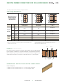
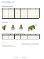
1
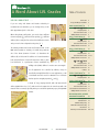
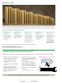
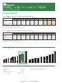
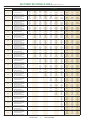
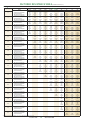
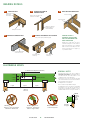
LVL User’s Guide
Technical Data for LVL Headers, Beams, Columns and Rim Board Applications
for Residential Floor and Roof Systems
CANADIAN VERSION
Quality Products – Committed Service
OUR HISTORY
In 1955, three Ketcham brothers, Henry Jr., William, and Samuel,
acquiring two sawmills in the U.S. south. A major acquisition occurred
started West Fraser by acquiring a small lumber planing mill in
in 2005 with the purchase of Weldwood of Canada. With this
Quesnel, BC. Throughout the years, they continued to make various
purchase, West Fraser entered the engineered wood business by
sawmill acquisitions in the interior of British Columbia, which
acquiring the world’s first continuous laminated veneer lumber press.
included the associated timber rights. In 1979, West Fraser entered
the pulp industry, constructing a joint venture mill in Quesnel. West
Fraser’s expansion continued into Alberta in 1989 when they entered
into a joint venture newsprint mill in Whitecourt. the Company’s
growth continued in Alberta with the acquisition of a sawmill, MDF
plant, and pulp mill in 1995 and a plywood mill, stud mill and veneer
West Fraser expanded further in 2007 when the Company acquired
13 additional sawmills in the southern U.S. from International Paper
Co. This added 1.8 billion board feet of lumber capacity to West Fraser
for a total capacity of more than 6 billion board feet, making West
Fraser one of the largest lumber producers in North America.
mill in 1999. In 2000, West Fraser entered the United States by
OUR ENVIRONMENTAL STEWARDSHIP
West Fraser Timber Co. Ltd. is committed to responsible stewardship of
• Preventing pollution and continuing to improve our environmental
the environment. A philosophy of continual improvement of our forest
performance by setting and reviewing environmental objectives
practices and manufacturing procedures has been adopted to optimize
and targets.
the use of resources and minimize or eliminate the impact of our
• Conducting periodic environmental audits.
operations on the environment.
• Providing training for employees and contractors to ensure
West Fraser recognizes that environmental excellence is an integral
aspect of long-term business success. Our Company and its employees
environmentally responsible work practices.
• Communicating our environmental performance to employees,
customers, shareholders, local communities and other stakeholders.
are committed to the following:
• Complying with all applicable environmental laws and regulations,
and with other requirements to which the organization subscribes.
• Reviewing, on a regular basis, this policy to ensure that it reflects the
Company’s ongoing commitment to environmental stewardship.
OUR VISION
West Fraser’s vision is to be the leading forest products company in Canada. Our goals are simple – leadership in profits, responsibility in
communities, excellence in people and strength in products.
LVL USER’S GUIDE
2
WEST FRASER TIMBER
A Word About LVL Grades
Table of Contents
Product Line 4
Storage, Handling & Installation 4
DID YOU KNOW THAT . . .
If you are using 2.0E beams and headers exclusively in
3100Fb 2.0E WEST FRASER™ LVL
5
1³⁄₄” AND 3¹⁄₂” THICK
residential wood construction, you are leaving money on the
Design Properties 6
Factored Resistance Table 7 – 8
Multiple Member Connections 9
table approximately 85% of the time.
When sizing beams and headers, you need to have sufficient
3000Fb 1.9E WEST FRASER™ LVL
11
1³⁄₄” THICK
moment capacity (Fb), sufficient shear capacity (Fv), sufficient
stiffness (EI) to satisfy the live and total load deflection criteria
Design Properties 12
Factored Resistance Table 13 – 14
Multiple Member Connections 15
and you need to have adequate bearing sizes (Fc i ).
The industry markets LVL beams and headers based on the
3000Fb 1.8E WEST FRASER™ LVL
17
1¹⁄₂” THICK
MOE value (modulus of elasticity = E) which along with the
size of the beam (moment of inertia = I) determines the
Design Properties 18
Factored Resistance Table 19 – 20
Multiple Member Connections 21
stiffness (EI) of the beam. The stiffness of a beam determines
how much deflection a beam will experience under a given
1³⁄₄” AND 3¹⁄₂” THICK
load. Deflection is a performance criteria established by
building codes (L/360). Stiffness is not the same as strength!
Not all applications are controlled by stiffness, many are
controlled by strength (Fb and Fv). In some applications, a 1.9E
or 2.0E beam cannot be used as a substitute for a 1.8E beam
that has superior strength properties (Fb and Fv).
A beam 16’ long, carrying 300 PLF, with 1.9E material will
deflect 0.0344 inches less (¹⁄₃₂”) under total load compared to the same beam with 1.8E
material. This is not much, especially when you consider the premium you pay for high MOE
products.
Design Properties
Factored Resistance Table
Multiple Member Connections
Columns
22
23 – 24
25
26
2750Fb 1.7E WEST FRASER™ LVL
27
1³⁄₄” AND 3¹⁄₂” THICK
Design Properties 28
1700Fb 1.3E WEST FRASER™ LVL
29
1¹⁄₄” THICK
Design Properties
Factored Resistance Table
1.3E LVL When Used As Rim Board
Multiple Member Connections
30
31
31
32
MISCELLANEOUS DETAILS, SOFTWARE
AND WARRANTY INFORMATION
33
Bearing Details
Allowable Holes
Minimum Nail Spacing
Our Weather Resistant Coating
Our Software
Warranty / Contact Information
LVL USER’S GUIDE
3
WEST FRASER TIMBER
34
34
35
35
35
Back cover
PRODUCT LINE
With the use of ultrasonic grading technology, West Fraser wisely utilizes the inherent attributes of its wood resources to manufacture products that
effectively satisfy the needs of the market while at the same time, contribute to a greener, more sustainable environment. In addition, these attributes
also allow for superior fiber bending strength and workability.
West Fraser™ LVL
3100Fb -2.0E
West Fraser™ LVL
3000Fb -1.9E
West Fraser™ LVL
3000Fb -1.8E
West Fraser™ LVL
2750Fb -1.7E
West Fraser™ LVL
1700Fb -1.3E
• 1³⁄₄” and 3¹⁄₂” thick
in I-Joist and lumber
compatible depths
to 24” deep
• 1³⁄₄” thick in I-Joist and
lumber compatible
depths to 24” deep
• 1¹⁄₂”, 1³⁄₄”, and 3¹⁄₂”
thick in I- Joist and
lumber compatible
depths to 18”. (1³⁄₄”
and 3¹⁄₂” to 24”), 3¹⁄₂”
thick in columns
• 1³⁄₄” and 3¹⁄₂” thick
in I-Joist and lumber
compatible depths
to 24” deep
• 1¹⁄₄” LVL structural rim,
starter joists, stair
stringers, joists and
stringers (single or
double) and multi-ply
headers (dimensional
lumber replacement)
All products have face, back and edges sealed for improved performance under normal construction exposure
CODE EVALUATION REPORT NUMBERS: CCMC 12904-R
Check product availability with supplier prior to specifying LVL sizes.
STORAGE, HANDLING AND INSTALLATION
Failure to follow good procedures for installation, storage and handling could result in unsatisfactory performance and unsafe structures.
•
West Fraser™ LVL should be stored lying
flat and protected from the weather.
•
Stickers to be aligned one above
the other and spaced no more than
8’-0” apart.
•
Do not exceed a storage bundle height
of 10’-0”.
•
Keep the material above ground to
minimize the absorption of ground
moisture and allow circulation of air.
•
Report all forklift damage prior to
shipment.
•
West Fraser™ LVL is for use in covered,
dry conditions only. Protect from the
weather on the job site both before and
after installation.
•
Except for cutting to length, West
Fraser™ LVL shall not be cut, drilled or
notched. Heel cuts may be possible.
Contact your West Fraser representative.
•
Place first set of stickers on hard, level
dry surface.
•
Do not install any damaged LVL.
CAUTION: Wrap may be slippery when wet
10’-0”
max.
Align stickers
one above
the other
Hard, dry,
level surface
These are general recommendations and in some cases, additional precautions may be required.
LVL USER’S GUIDE
4
WEST FRASER TIMBER
8’-0” max.
3100F b – 2.0E LVL
LVL USER’S GUIDE
5
WEST FRASER TIMBER
3100F b – 2.0E 1 3/ 4” and 3 1/ 2” THICK
HEADERS AND BEAMS
DESIGN PROPERTIES
3100Fb-2.0E 1³⁄₄” WEST FRASER™ LVL FACTORED RESISTANCES (STANDARD TERM)
Depth
Design Property
Moment (ft.lbs.)
Shear (lbs.)
Moment of Inertia (in^4)
Weight (lbs./lin.ft.)
5¹⁄₂"
4134
3736
24
2.7
7¹⁄₄"
6967
4925
56
3.6
9¹⁄₄"
11037
6284
115
4.6
9¹⁄₂"
11608
6454
125
4.7
11¹⁄₂"
16652
7813
222
5.7
11⁷⁄₈"
17693
8067
244
5.9
14"
24146
9511
400
7.0
16"
31073
10870
597
8.0
18"
38816
12228
851
9.0
24"
66835
16304
2016
12.0
11⁷⁄₈"
35386
16135
488
11.8
14"
48292
19022
800
14.0
16"
62146
21739
1195
15.9
18"
77631
24457
1701
17.9
24"
133669
32609
4032
23.9
1. Lateral support of beam compression edge is required at intervals of 24” o/c or closer.
2. Lateral support of beam is required at bearing locations.
3. All 16” and greater beam depths are to be used in multiple member units only.
3100Fb-2.0E 3¹⁄₂” WEST FRASER™ LVL FACTORED RESISTANCES (STANDARD TERM)
Depth
Design Property
Moment (ft.lbs.)
Shear (lbs.)
Moment of Inertia (in^4)
Weight (lbs./lin.ft.)
5¹⁄₂"
8269
7473
49
5.5
7¹⁄₄"
13933
9851
111
7.2
9¹⁄₄"
22075
12568
231
9.2
9¹⁄₂"
23215
12908
250
9.5
11¹⁄₂"
33305
15625
444
11.5
1. Lateral support of beam compression edge is required at intervals of 24” o/c or closer.
2. Lateral support of beam is required at bearing locations.
3100Fb -2.0E 1³⁄₄” AND 3¹⁄₂” WEST FRASER™ LVL AVAILABLE SIZES
51⁄ 2”
71⁄₄”
9 1⁄₄”
9 1⁄ 2”
111⁄ 2”
117⁄ 8”
14”
16”*
18”*
24”*
5 1⁄ 2”
71⁄₄”
9 1⁄₄”
9 1⁄ 2”
111⁄ 2”
117⁄ 8”
14”
16”
*can only be used as a 2-ply minimum
3100Fb -2.0E WEST FRASER™ LVL SPECIFIED STRENGTHS (STANDARD TERM)
Modulus of Elasticity
Bending Stress
Shear (joist)
Compression Perpendicular to Grain (joist)
Compression Parallel to Grain
1. Fb based on 12” depths. For other depths, multiply by (12/d)^(1/9).
2. Fc(perp) and E shall not be increased for duration of load.
E = 2.0 x 10^6 psi
Fb = 5729 psi
Fv = 647 psi
Fc(perp) = 1300 psi
Fc(para) = 4786 psi
LVL USER’S GUIDE
6
WEST FRASER TIMBER
18”
24”
FACTORED RESISTANCE TABLES
GENERAL NOTES
•
•
•
Tables are for one-ply 1³⁄₄” beams. When properly connected, double
the values for two-ply beams, triple for three. Minimum bearing lengths
shown for one-ply will be the same for two-ply and three-ply. See page
9 for multiple-ply connection details.
Resistances shown are the maximum factored and/or unfactored
resistances, in pounds per lineal foot, that can be applied to the beam
in addition to its own weight.
Tables are based on uniform loads and the most restrictive of simple or
continuous spans and dry-use conditions. Refer to West Fraser’s sizing
software for other loads or span configurations.
•
Lateral support of beam compression edges is required at intervals of
24” o/c or closer.
•
Lateral support of beams is required at bearing locations.
•
Spans of multiple spans must be at least 40% of adjacent span.
•
West Fraser™ LVL beams are made without camber; therefore, in
addition to complying with the deflection limits of the applicable
building code, other deflection considerations, such as long term
deflection under sustained loads (including creep), must be evaluated.
•
All 16” and deeper beams are to be used in multiple member units only.
•
Unfactored total load resistance is limited to a deflection of L/240.
Unfactored live load resistance is based on a deflection of L/360.
Check local code requirements for other deflection criteria.
•
For an unfactored live load deflection limit of L/480, multiply
UNFACTORED LOAD L/360 resistance by 0.75. The resulting unfactored
live load shall not exceed the total factored load shown.
•
Roof must have positive slope in order to prevent ponding.
•
Tables will accommodate beam slopes to a maximum of 2:12.
•
Bearing lengths are based on 1300 psi specified strength for
3100Fb-2.0E Grade materials which cannot be increased for duration
of load. Bearing length may need to be increased if support member’s
allowable bearing stress is less.
•
Spans shown are measured centre-to-centre of bearing.
INSTRUCTIONS FOR USE
1. Determine the factored total load and unfactored total and live
load on the beam in pounds per lineal foot (plf).
2. Locate a span that meets or exceeds the required beam span,
centre-to-centre of bearing.
3. Scan from left to right within the SPAN row until you find a cell where;
(1) the UNFACTORED LOAD L/360 resistance meets or exceeds the
unfactored live load, (2) the UNFACTORED LOAD L/240 resistance
LVL USER’S GUIDE
7
meets or exceeds the unfactored total load and (3) the FACTORED
TOTAL LOAD resistance meets or exceeds the factored total load. All
three rows must be checked and satisfied. Where no unfactored
resistances are shown, factored total load will control.
4. To size a member for a span not shown, use capacities for the next
larger span shown.
WEST FRASER TIMBER
FACTORED RESISTANCE TABLE (POUNDS PER LINEAL FOOT)
3100Fb-2.0E West Fraser LVL — FLOOR or ROOF (Standard Term)
™
Span (ft)
Depth
5-1/2"
7-1/4"
Unfactored Load (LL) L/360
305
660
455
986
Unfactored Load (TL) L/240
6
916
1545
Factored Total Load
1.5/3.8
2.5/6.4
Min. End / Int. Bearing (in)
197
431
Unfactored Load (LL) L/360
292
643
Unfactored Load (TL) L/240
7
672
1134
Factored Total Load
1.5/3.5
2.2/5.5
Min. End / Int. Bearing (in)
134
296
Unfactored Load (LL) L/360
198
440
Unfactored Load (TL) L/240
8
514
867
Factored Total Load
1.5/3.5
1.9/4.8
Min. End / Int. Bearing (in)
95
211
Unfactored Load (LL) L/360
140
313
Unfactored Load (TL) L/240
9
406
684
Factored Total Load
1.5/3.5
1.7/4.2
Min. End / Int. Bearing (in)
70
156
Unfactored Load (LL) L/360
102
230
Unfactored Load (TL) L/240
10
328
554
Factored Total Load
1.5/3.5
1.5/3.8
Min. End / Int. Bearing (in)
118
Unfactored Load (LL) L/360
174
Unfactored Load (TL) L/240
11
457
Factored Total Load
1.5/3.5
Min. End / Int. Bearing (in)
92
Unfactored Load (LL) L/360
134
Unfactored Load (TL) L/240
12
383
Factored Total Load
1.5/3.5
Min. End / Int. Bearing (in)
73
Unfactored Load (LL) L/360
105
Unfactored Load (TL) L/240
13
326
Factored Total Load
1.5/3.5
Min. End / Int. Bearing (in)
58
Unfactored Load (LL) L/360
84
Unfactored Load (TL) L/240
14
281
Factored Total Load
1.5/3.5
Min. End / Int. Bearing (in)
48
Unfactored Load (LL) L/360
68
Unfactored Load (TL) L/240
15
244
Factored Total Load
1.5/3.5
Min. End / Int. Bearing (in)
Unfactored Load (LL) L/360
Unfactored Load (TL) L/240
16
Factored Total Load
Min. End / Int. Bearing (in)
Unfactored Load (LL) L/360
Unfactored Load (TL) L/240
17
Factored Total Load
Min. End / Int. Bearing (in)
Unfactored Load (LL) L/360
Unfactored Load (TL) L/240
18
Factored Total Load
Min. End / Int. Bearing (in)
Unfactored Load (LL) L/360
Unfactored Load (TL) L/240
19
Factored Total Load
Min. End / Int. Bearing (in)
Unfactored Load (LL) L/360
Unfactored Load (TL) L/240
20
Factored Total Load
Min. End / Int. Bearing (in)
Unfactored Load (LL) L/360
Unfactored Load (TL) L/240
21
Factored Total Load
Min. End / Int. Bearing (in)
Unfactored Load (LL) L/360
Unfactored Load (TL) L/240
22
Factored Total Load
Min. End / Int. Bearing (in)
Unfactored Load (LL) L/360
Unfactored Load (TL) L/240
23
Factored Total Load
Min. End / Int. Bearing (in)
Unfactored Load (LL) L/360
Unfactored Load (TL) L/240
24
Factored Total Load
Min. End / Int. Bearing (in)
Unfactored Load (LL) L/360
Unfactored Load (TL) L/240
26
Factored Total Load
Min. End / Int. Bearing (in)
Unfactored Load (LL) L/360
Unfactored Load (TL) L/240
28
Factored Total Load
Min. End / Int. Bearing (in)
Unfactored Load (LL) L/360
Unfactored Load (TL) L/240
30
Factored Total Load
Min. End / Int. Bearing (in)
* All 16”, 18” and 24” beam depths are to be used in multiple member units only.
LVL USER’S GUIDE
9-1/4"
1263
1890
2105
3.5/8.7
840
1256
1739
3.3/8.4
585
872
1375
3.0/7.6
422
628
1086
2.7/6.7
313
465
878
2.4/6.0
239
354
725
2.2/5.5
186
275
609
2.0/5.0
148
217
518
1.9/4.6
119
174
446
1.7/4.3
97
141
388
1.6/4.0
81
116
340
1.5/3.7
67
97
301
1.5/3.5
57
81
268
1.5/3.5
8
9-1/2"
1353
2025
2177
3.6/9.0
903
1349
1796
3.5/8.6
629
939
1446
3.2/7.9
454
677
1142
2.8/7.1
338
502
924
2.5/6.3
258
382
763
2.3/5.8
201
297
640
2.1/5.3
160
235
545
1.9/4.9
129
188
469
1.8/4.5
105
153
408
1.7/4.2
87
126
358
1.6/3.9
73
105
317
1.5/3.7
62
88
282
1.5/3.5
53
74
253
1.5/3.5
1³⁄₄” WIDTH
11-1/2"
2186
11-7/8"
2363
14"
3473
16"
18"
24"
2793
4.6/11.5
1488
2226
2281
4.4/11.0
1052
1572
1927
4.2/10.6
768
1146
1639
4.1/10.1
576
858
1326
3.6/9.1
442
658
1095
3.3/8.3
346
514
919
3.0/7.6
276
408
783
2.8/7.0
223
329
674
2.6/6.5
183
269
586
2.4/6.0
152
222
515
2.3/5.7
128
186
455
2.1/5.3
108
156
405
2.0/5.0
92
133
363
1.9/4.7
79
113
327
1.8/4.5
69
97
296
1.7/4.3
60
84
270
1.6/4.1
2917
4.8/12.0
1614
3675
6.1/15.1
2423
4490
7.4/18.5
3313
5426
8.9/22.4
9305
15.3/38.3
2377
4.6/11.4
1144
1711
2006
4.4/11.0
837
1250
1734
4.3/10.7
629
938
1410
3.9/9.7
484
719
1164
3.5/8.8
379
563
977
3.2/8.1
302
448
832
3.0/7.4
245
361
716
2.8/6.9
201
296
623
2.6/6.4
167
244
547
2.4/6.0
140
204
484
2.3/5.7
119
172
431
2.1/5.3
101
146
386
2.0/5.0
87
125
348
1.9/4.8
76
107
315
1.8/4.5
66
93
287
1.7/4.3
58
81
262
1.7/4.1
2957
5.7/14.2
1746
3566
6.9/17.1
2423
4244
8.2/20.4
3196
6853
13.2/32.9
2474
5.4/13.6
1293
1932
2126
5.3/13.1
981
1464
1864
5.1/12.8
760
1132
1589
4.8/12.0
599
892
1334
4.4/11.0
480
713
1136
4.1/10.1
390
579
979
3.8/9.4
321
475
852
3.5/8.8
268
394
748
3.3/8.2
225
331
661
3.1/7.7
191
279
589
2.9/7.3
163
238
528
2.8/6.9
141
204
476
2.6/6.5
122
176
431
2.5/6.2
107
153
392
2.4/5.9
94
134
358
2.3/5.7
83
117
328
2.2/5.4
65
91
279
2.0/5.0
53
72
239
1.8/4.6
2956
6.5/16.2
1816
3485
7.7/19.1
2423
5423
11.9/29.8
2525
6.2/15.6
1390
2077
2203
6.1/15.1
1085
1619
1953
5.9/14.8
861
1283
1718
5.7/14.2
694
1032
1463
5.2/13.1
566
841
1260
4.8/12.1
468
694
1097
4.5/11.3
390
578
963
4.2/10.6
329
486
852
4.0/9.9
280
412
759
3.8/9.4
240
352
681
3.6/8.9
207
303
613
3.4/8.4
180
262
556
3.2/8.0
157
228
506
3.1/7.6
138
200
462
2.9/7.3
122
175
424
2.8/7.0
97
137
360
2.6/6.4
78
109
309
2.4/5.9
64
87
268
2.2/5.5
2955
7.3/18.3
1873
4486
11.1/27.7
3700
2565
7.0/17.6
1473
2200
2266
6.8/17.1
1176
1755
2029
6.7/16.7
952
1419
1828
6.5/16.3
781
1162
1575
6.1/15.1
647
962
1371
5.6/14.1
542
804
1204
5.3/13.2
458
678
1066
5.0/12.4
390
577
949
4.7/11.7
335
494
851
4.4/11.1
290
426
767
4.2/10.5
252
370
695
4.0/10.0
221
322
633
3.8/9.6
194
283
578
3.7/9.1
172
249
530
3.5/8.7
136
196
450
3.2/8.0
110
156
387
3.0/7.4
90
126
336
2.8/6.9
3824
10.5/26.3
2976
WEST FRASER TIMBER
3333
10.1/25.2
2423
2952
9.7/24.3
1994
2650
9.5/23.7
1657
2404
9.2/23.1
1390
2073
2199
9.1/22.7
1176
1752
2026
8.9/22.3
1003
1492
1838
8.6/21.5
861
1279
1638
8.1/20.3
744
1104
1469
7.7/19.2
647
959
1325
7.3/18.2
566
837
1200
6.9/17.3
498
735
1093
6.6/16.5
440
648
999
6.3/15.8
390
574
916
6.0/15.1
312
455
779
5.6/13.9
252
367
670
5.2/12.9
207
299
582
4.8/12.0
MULTIPLE MEMBER CONNECTIONS FOR SIDE-LOADED BEAMS: 3100Fb – 2.0E
Verify adequacy of beam in uniform load tables prior to using values listed below.
3100Fb-2.0E 1³₄” WEST FRASER™ LVL
2”
2”
2”
2”
2”
2”
Maximum Factored
Uniform Load (PLF)
Applied to Either
Outside Member
2-PLY LVL
3-PLY LVL
4-PLY LVL*
Nails On One Side
or Through Bolts
Nails Both Sides
or Through Bolts
Through Bolts
Only
2 Rows
885
663
3 Rows
1327
995
2 Rows
1770
1326
3 Rows
2654
1990
2 Rows
2655
1989
3 Rows
3981
2985
24” o.c.
2 Rows
671
503
448
12” o.c.
2 Rows
1342
1006
895
6” o.c.
2 Rows
2684
2012
1790
Connector Spacing
12” o.c.
16d (3¹⁄₂”)
Common
Wire Nails
6” o.c.
4” o.c.
¹⁄₂” A307
Through
Bolts
Rows
Not Applicable
Not Applicable
Not Applicable
2. Bolts are to be material conforming to ASTM Standard A307. Bolt holes are to be the same
diameter as the bolt, and located 2” from the top and bottom of the member. Washers should
be used under head and nut. Start all bolts a minimum of 2¹⁄₂” in from ends.
3. Values listed are for standard term loading.
* 4-ply beams should only be side-loaded when loads are applied to both sides of the member.
1. Nails to be located a minimum of 2” from the top and bottom of the member. Start all nails
a minimum of 2¹⁄₂” in from ends.
400 lbs.
EXAMPLE
533 lbs.
(All loads shown are total factored)
First, convert joist reactions to plf load on each side of the beam by taking the joist reaction (lbs.) divided by
the joist spacing (ft.). 400 lbs/(16/12) = 300 plf and 533 lbs/(16/12) = 400 plf. Check factored resistance
tables to verify that 3 plys can carry the total factored load of 700 plf. The maximum load applied to either
outside member is 400 plf. Use 2 rows of 16d (3¹⁄₂”) common wire nails at 12” o.c. (good for 663 plf).
Joists Spaced
at 16” o.c.
CONNECTION OF MULTIPLE PIECES FOR TOP-LOADED BEAMS
2.0E (1³⁄₄” wide pieces)
•
Minimum of 2 rows of 16d (3¹⁄₂”) nails at 12” o.c. for 5¹⁄₂” through 11⁷⁄₈” beams
•
Minimum of 3 rows of 16d (3¹⁄₂”) nails at 12” o.c. for 14” through 24” beams
LVL USER’S GUIDE
9
WEST FRASER TIMBER
NOTES
LVL USER’S GUIDE
10
WEST FRASER TIMBER
3000F b – 1.9E LVL
LVL USER’S GUIDE
11
WEST FRASER TIMBER
LVL 3000F b – 1.9E 1 3/ 4” THICK
HEADERS AND BEAMS
DESIGN PROPERTIES
3000Fb-1.9E 1³⁄₄” WEST FRASER™ LVL FACTORED RESISTANCES (STANDARD TERM)
Depth
Design Property
Moment (ft.lbs.)
Shear (lbs.)
Moment of Inertia (in^4)
Weight (lbs./lin.ft.)
5¹⁄₂"
4079
3736
24
2.7
7¹⁄₄"
6827
4925
56
3.6
9¹⁄₄"
10751
6284
115
4.6
9¹⁄₂"
11299
6454
125
4.7
11¹⁄₂"
16132
7813
222
5.7
11⁷⁄₈"
17126
8067
244
5.9
14"
23277
9511
400
7.0
16"
29855
10870
597
8.0
18"
37184
12228
851
9.0
24"
63568
16304
2016
12.0
1. Lateral support of beam compression edge is required at intervals of 24” o/c or closer.
2. Lateral support of beam is required at bearing locations.
3. All 16” and greater beam depths are to be used in multiple member units only.
3000Fb - 1.9E 1³⁄₄” WEST FRASER™ LVL AVAILABLE SIZES*
51⁄ 2”
71⁄₄”
91⁄₄”
9 1⁄ 2”
111⁄ 2”
117⁄ 8”
14”
16”*
18”*
24”*
*can only be used as a 2-ply minimum
3000Fb -1.9E WEST FRASER™ LVL SPECIFIED STRENGTHS (STANDARD TERM)
Modulus of Elasticity
Bending Stress
Shear (joist)
E
=
1.9 x 10^6 psi
Fb
=
5544 psi
Fv
=
647 psi
Compression Perpendicular to Grain (joist)
Fc(perp)
=
1300 psi
Compression Parallel to Grain
Fc(para)
=
4000 psi
1. Fb based on 12” depths. For other depths, multiply by (12/d)^(1/7.35).
2. Fc(perp) and E shall not be increased for duration of load.
LVL USER’S GUIDE
12
WEST FRASER TIMBER
5 1⁄ 2”
FACTORED RESISTANCE TABLES
GENERAL NOTES
•
Tables are for one-ply 1³⁄₄” beams. When properly connected, double
the values for two-ply beams, triple for three. Minimum bearing lengths
shown for one-ply will be the same for two-ply and three-ply. See page
15 for multiple-ply connection details.
•
Resistances shown are the maximum factored and/or unfactored
resistances, in pounds per lineal foot, that can be applied to the beam
in addition to its own weight.
•
Tables are based on uniform loads and the most restrictive of simple or
continuous spans and dry-use conditions. Refer to West Fraser’s sizing
software for other loads or span configurations.
•
Lateral support of beam compression edges is required at intervals of
24” o/c or closer.
•
Lateral support of beams is required at bearing locations.
•
West Fraser™ LVL beams are made without camber; therefore, in
addition to complying with the deflection limits of the applicable
building code, other deflection considerations, such as long term
deflection under sustained loads (including creep), must be evaluated.
•
All 16” and deeper beams are to be used in multiple member units only.
•
Unfactored total load resistance is limited to a deflection of L/240.
Unfactored live load resistance is based on a deflection of L/360.
Check local code requirements for other deflection criteria.
•
For an unfactored live load deflection limit of L/480, multiply
UNFACTORED LOAD L/360 resistance by 0.75.
•
Roof must have positive slope in order to prevent ponding.
•
Spans of multiple spans must be at least 40% of adjacent span.
•
Bearing lengths are based on 1300 psi specified strength for
1.9E Grade materials which cannot be increased for duration
of load. Bearing length may need to be increased if support member’s
allowable bearing stress is less.
•
Tables will accommodate beam slopes to a maximum of 2:12.
INSTRUCTIONS FOR USE
1. Determine the factored total load and unfactored total and live load on the beam in pounds per lineal foot (plf).
2. Locate a span that meets or exceeds the required beam span, centre-to-centre of bearing.
3. Scan from left to right within the SPAN row until you find a cell where; (1) the UNFACTORED LOAD L/360 resistance meets or exceeds the unfactored live load,
(2) the UNFACTORED LOAD L/240 resistance meets or exceeds the unfactored total load and (3) the FACTORED TOTAL LOAD resistance meets or exceeds the
factored total load. All three rows must be checked and satisfied. Where no unfactored resistances are shown, factored total load will control.
4. To size a member for a span not shown, use capacities for the next larger span shown.
LVL USER’S GUIDE
13
WEST FRASER TIMBER
FACTORED RESISTANCE TABLE (POUNDS PER LINEAL FOOT)
3000Fb-1.9E West Fraser™ LVL — FLOOR or ROOF (Standard Term)
1³⁄₄” WIDTH
Span (ft)
5-1/2"
7-1/4"
Depth
627
290
Unfactored Load (LL) L/360
433
936
Unfactored Load (TL) L/240
6
904
1514
Factored Total Load
1.5/3.7
2.5/6.2
Min. End / Int. Bearing (in)
409
187
Unfactored Load (LL) L/360
277
610
Unfactored Load (TL) L/240
7
663
1111
Factored Total Load
1.5/3.5
2.1/5.3
Min. End / Int. Bearing (in)
281
127
Unfactored Load (LL) L/360
188
418
Unfactored Load (TL) L/240
8
507
850
Factored Total Load
1.5/3.5
1.9/4.7
Min. End / Int. Bearing (in)
90
201
Unfactored Load (LL) L/360
297
132
Unfactored Load (TL) L/240
9
400
671
Factored Total Load
1.5/3.5
1.7/4.1
Min. End / Int. Bearing (in)
66
148
Unfactored Load (LL) L/360
219
97
Unfactored Load (TL) L/240
10
324
543
Factored Total Load
1.5/3.7
1.5/3.5
Min. End / Int. Bearing (in)
112
Unfactored Load (LL) L/360
165
Unfactored Load (TL) L/240
11
448
Factored Total Load
1.5/3.5
Min. End / Int. Bearing (in)
87
Unfactored Load (LL) L/360
127
Unfactored Load (TL) L/240
12
376
Factored Total Load
1.5/3.5
Min. End / Int. Bearing (in)
69
Unfactored Load (LL) L/360
100
Unfactored Load (TL) L/240
13
320
Factored Total Load
1.5/3.5
Min. End / Int. Bearing (in)
55
Unfactored Load (LL) L/360
80
Unfactored Load (TL) L/240
14
275
Factored Total Load
1.5/3.5
Min. End / Int. Bearing (in)
45
Unfactored Load (LL) L/360
64
Unfactored Load (TL) L/240
15
239
Factored Total Load
1.5/3.5
Min. End / Int. Bearing (in)
Unfactored Load (LL) L/360
Unfactored Load (TL) L/240
16
Factored Total Load
Min. End / Int. Bearing (in)
Unfactored Load (LL) L/360
Unfactored Load (TL) L/240
17
Factored Total Load
Min. End / Int. Bearing (in)
Unfactored Load (LL) L/360
Unfactored Load (TL) L/240
18
Factored Total Load
Min. End / Int. Bearing (in)
Unfactored Load (LL) L/360
Unfactored Load (TL) L/240
19
Factored Total Load
Min. End / Int. Bearing (in)
Unfactored Load (LL) L/360
Unfactored Load (TL) L/240
20
Factored Total Load
Min. End / Int. Bearing (in)
Unfactored Load (LL) L/360
Unfactored Load (TL) L/240
21
Factored Total Load
Min. End / Int. Bearing (in)
Unfactored Load (LL) L/360
Unfactored Load (TL) L/240
22
Factored Total Load
Min. End / Int. Bearing (in)
Unfactored Load (LL) L/360
Unfactored Load (TL) L/240
23
Factored Total Load
Min. End / Int. Bearing (in)
Unfactored Load (LL) L/360
Unfactored Load (TL) L/240
24
Factored Total Load
Min. End / Int. Bearing (in)
Unfactored Load (LL) L/360
Unfactored Load (TL) L/240
26
Factored Total Load
Min. End / Int. Bearing (in)
Unfactored Load (LL) L/360
Unfactored Load (TL) L/240
28
Factored Total Load
Min. End / Int. Bearing (in)
Unfactored Load (LL) L/360
Unfactored Load (TL) L/240
30
Factored Total Load
Min. End / Int. Bearing (in)
* All 16”, 18” and 24” beam depths are to be used in multiple member units only.
LVL USER’S GUIDE
9-1/4"
1200
1795
2105
3.5/8.7
798
1193
1739
3.3/8.4
555
828
1339
2.9/7.4
401
596
1057
2.6/6.5
298
442
855
2.3/5.9
227
336
706
2.1/5.3
177
261
593
2.0/4.9
140
206
504
1.8/4.5
113
165
434
1.7/4.2
93
134
378
1.6/3.9
77
110
331
1.5/3.6
64
92
293
1.5/3.5
54
77
261
1.5/3.5
14
9-1/2"
1286
1924
2177
3.6/9.0
858
1282
1796
3.5/8.6
598
892
1408
3.1/7.7
431
643
1111
2.7/6.9
321
477
899
2.5/6.2
245
363
742
2.2/5.6
191
282
623
2.1/5.1
152
223
530
1.9/4.7
122
179
456
1.8/4.4
100
145
397
1.6/4.1
83
119
348
1.5/3.8
69
99
308
1.5/3.6
59
83
274
1.5/3.5
50
70
246
1.5/3.5
11-1/2"
2077
11-7/8"
2245
14"
3299
16"
4427
18"
24"
2793
4.6/11.5
1413
2114
2281
4.4/11.0
999
1493
1927
4.2/10.6
729
1088
1588
3.9/9.8
547
815
1285
3.5/8.8
420
624
1061
3.2/8.0
329
488
890
2.9/7.3
262
388
758
2.7/6.8
212
313
653
2.5/6.3
174
255
568
2.3/5.9
144
211
498
3.2/5.5
121
176
441
2.1/5.1
103
148
393
1.9/4.9
88
126
352
1.8/4.6
75
107
317
1.7/4.4
65
92
287
1.7/4.1
57
80
261
1.6/3.9
2917
4.8/12.0
1533
2294
2377
4.6/11.4
1087
1625
2006
4.4/11.0
795
1187
1686
4.2/10.4
598
890
1364
3.7/9.4
459
683
1126
3.4/8.5
360
534
946
3.1/7.8
287
425
805
2.9/7.2
233
343
693
2.7/6.7
191
280
603
2.5/6.2
159
232
529
2.3/5.8
133
194
468
2.2/5.5
113
163
417
2.1/5.2
96
138
374
2.0/4.9
83
118
337
1.9/4.6
72
102
305
1.8/4.4
63
88
277
1.7/4.2
55
76
253
1.6/4.0
3675
6.1/15.1
2302
4490
7.4/18.5
3148
5426
8.9/22.4
4093
9305
15.3/38.3
2957
5.7/14.2
1658
3566
6.9/17.1
2302
4244
8.2/20.4
3036
6853
13.2/32.9
2474
5.4/13.6
1228
1835
2126
5.3/13.1
932
1390
1855
5.1/12.7
722
1075
1532
4.6/11.6
569
847
1286
4.2/10.6
456
677
1095
3.9/9.8
371
549
943
3.6/9.1
305
451
821
3.4/8.5
254
374
720
3.2/7.9
214
314
637
3.0/7.4
181
265
568
2.8/7.0
155
226
509
2.7/6.6
134
194
459
2.5/6.3
116
167
415
2.4/6.0
101
145
378
2.3/5.7
89
127
345
2.2/5.4
79
111
316
2.1/5.2
62
86
268
1.9/4.8
50
68
231
1.8/4.4
2956
6.5/16.2
1725
3485
7.7/19.1
2302
5423
11.9/29.8
4427
2525
6.2/15.6
1321
1973
2203
6.1/15.1
1031
1538
1953
5.9/14.8
818
1219
1651
5.4/13.6
659
980
1405
5.0/12.5
538
799
1211
4.7/11.6
444
658
1054
4.3/10.9
371
548
925
4.1/10.2
313
461
818
3.8/9.6
266
391
729
3.6/9.0
228
334
654
3.4/8.5
197
287
589
3.2/8.1
171
248
534
3.1/7.7
149
216
485
2.9/7.3
131
189
444
2.8/7.0
116
166
407
2.7/6.7
92
130
345
2.5/6.2
74
103
297
2.3/5.7
60
83
257
2.1/5.3
2955
7.3/18.3
1779
4486
11.1/27.7
3515
2565
7.0/17.6
1399
2090
2266
6.8/17.1
1117
1667
2029
6.7/16.7
905
1348
1751
6.3/15.6
742
1104
1509
5.8/14.5
615
913
1313
5.4/13.5
515
763
1153
5.1/12.7
435
644
1020
4.8/11.9
371
547
909
4.5/11.2
319
469
815
4.3/10.6
275
404
735
4.0/10.1
240
351
666
3.8/9.6
210
306
606
3.7/9.2
185
268
553
3.5/8.7
163
236
507
3.3/8.4
130
185
431
3.1/7.7
104
148
370
2.8/7.1
85
119
322
2.7/6.6
3824
10.5/26.3
2828
WEST FRASER TIMBER
3333
10.1/25.2
2302
2952
9.7/24.3
1894
2650
9.5/23.7
1574
2350
2404
9.2/23.1
1321
1969
2199
9.1/22.7
1117
1664
1974
8.7/21.7
953
1417
1748
8.2/20.4
818
1215
1558
7.7/19.3
707
1049
1397
7.3/18.2
615
910
259
6.9/17.3
538
795
1141
6.6/16.5
473
697
1039
6.3/15.7
418
615
949
6.0/15.0
371
544
871
5.7/14.4
296
432
740
5.3/13.2
240
348
637
4.9/12.3
197
283
553
4.6/11.4
MULTIPLE MEMBER CONNECTIONS FOR SIDE-LOADED BEAMS: 3000Fb – 1.9E
Verify adequacy of beam in uniform load tables prior to using values listed below.
3000Fb-1.9E 1³₄” WEST FRASER™ LVL
2”
2”
2”
2”
2”
2”
Maximum Factored
Uniform Load (PLF)
Applied to Either
Outside Member
2-PLY LVL
Connector
Spacing
12” o.c.
16d (3¹⁄₂”)
Common
Wire Nails
6” o.c.
4” o.c.
¹⁄₂” A307
Through
Bolts
3-PLY LVL
Rows
Nails On One Side
or Through Bolts
Nails Both Sides
or Through Bolts
2 Rows
827
620
3 Rows
1241
930
2 Rows
1654
1240
3 Rows
2482
1860
2 Rows
2481
1860
3 Rows
3723
2790
4-PLY LVL*
Through Bolts Only
Not Applicable
Not Applicable
Not Applicable
24” o.c.
2 Rows
671
503
448
12” o.c.
2 Rows
1342
1006
895
6” o.c.
2 Rows
2684
2012
1790
* 4-ply beams should only be side-loaded when loads are applied to both sides of the member.
2. Bolts are to be material conforming to ASTM Standard A307. Bolt holes are to be the same
diameter as the bolt, and located 2” from the top and bottom of the member. Washers should
be used under head and nut. Start all bolts a minimum of 2¹⁄₂” in from ends.
3. Values listed are for standard term loading.
1. Nails to be located a minimum of 2” from the top and bottom of the member. Start all nails
a minimum of 2¹⁄₂” in from ends.
400 lbs.
EXAMPLE
533 lbs.
(All loads shown are total factored)
First, convert joist reactions to plf load on each side of the beam by taking the joist reaction (lbs.) divided by
the joist spacing (ft.). 400 lbs/(16/12) = 300 plf and 533 lbs/(16/12) = 400 plf. Check factored resistance
tables to verify that 3 plys can carry the total factored load of 700 plf. The maximum load applied to either
outside member is 400 plf. Use 2 rows of 16d (3¹⁄₂”) common wire nails at 12” o.c. (good for 620 plf).
Joists Spaced
at 16” o.c.
CONNECTION OF MULTIPLE PIECES FOR TOP-LOADED BEAMS
1.9E (1³⁄₄” wide pieces)
•
Minimum of 2 rows of 16d (3¹⁄₂”) nails at 12” o.c. for 5¹⁄₂” through 11⁷⁄₈” beams
•
Minimum of 3 rows of 16d (3¹⁄₂”) nails at 12” o.c. for 14” through 24” beams
LVL USER’S GUIDE
15
WEST FRASER TIMBER
NOTES
LVL USER’S GUIDE
16
WEST FRASER TIMBER
3000F b – 1.8E LVL
LVL USER’S GUIDE
17
WEST FRASER TIMBER
LVL 3000F b – 1.8E 1 1/ 2” THICK
HEADERS AND BEAMS
DESIGN PROPERTIES
3000Fb-1.8E 1¹⁄₂” WEST FRASER™ LVL FACTORED RESISTANCES (STANDARD TERM)
Depth
Design Property
5¹⁄₂”
7¹⁄₄”
9¹⁄₄”
9¹⁄₂”
11¹⁄₂”
11⁷⁄₈”
14”
16”
18”
Moment (ft.lbs.)
3497
5852
9215
9684
13827
14679
19951
25590
31872
Shear (lbs.)
2653
3497
4462
4583
5548
5729
6754
7718
8683
Moment of Inertia (in^4)
21
48
99
107
190
209
343
512
729
Weight (lbs./lin.ft.)
2.1
2.8
3.6
3.7
4.4
4.6
5.4
6.2
6.9
1. Lateral support of beam compression edge is required at intervals of 24” o/c or closer.
2. Lateral support of beam is required at bearing locations.
3. All 14” and greater beam depths are to be used in multiple member units only (1¹⁄₂” thick).
3000Fb-1.8E 1¹⁄₂” WEST FRASER™ LVL AVAILABLE SIZES
51⁄ 2”
71⁄₄”
91⁄₄”
117⁄ 8”
111⁄ 2”
9 1⁄ 2”
14”*
16”*
18”*
*can only be used as a 2-ply minimum
3000Fb-1.8E WEST FRASER™ LVL SPECIFIED STRENGTHS (STANDARD TERM)
Modulus of Elasticity
Bending Stress
Shear (joist)
Compression Perpendicular to Grain (joist)
Compression Parallel to Grain
E
Fb
Fv
Fc(perp)
Fc(para)
=
=
=
=
=
1.8 x 10^6 psi
5544 psi
536 psi
1365 psi
3750 psi
1. Fb based on 12” depths. For other depths, multiply by (12/d)^(1/7.35) .
2. Fc(perp) and E shall not be increased for duration of load.
LVL USER’S GUIDE
18
WEST FRASER TIMBER
FACTORED RESISTANCE TABLES
GENERAL NOTES
•
•
•
Tables are for one-ply 1¹⁄₂” beams. When properly connected, double
the values for two-ply beams, triple for three. Minimum bearing lengths
shown for one-ply will be the same for two-ply and three-ply. See page
21 for multiple-ply connection details.
Resistances shown are the maximum factored and/or unfactored
resistances, in pounds per lineal foot, that can be applied to the beam
in addition to its own weight.
Tables are based on uniform loads and the most restrictive of simple or
continuous spans and dry-use conditions. Refer to West Fraser’s sizing
software for other loads or span configurations.
•
Lateral support of beam compression edges is required at intervals of
24” o/c or closer.
•
Lateral support of beams is required at bearing locations.
•
West Fraser™ LVL beams are made without camber; therefore, in
addition to complying with the deflection limits of the applicable
building code, other deflection considerations, such as long term
deflection under sustained loads (including creep), must be evaluated.
•
All 14” and deeper beams are to be used in multiple member units only.
•
Unfactored total load resistance is limited to a deflection of L/240.
Unfactored live load resistance is based on a deflection of L/360.
Check local code requirements for other deflection criteria.
•
For an unfactored live load deflection limit of L/480, multiply
UNFACTORED LOAD L/360 resistance by 0.75.
•
Roof must have positive slope in order to prevent ponding.
•
Spans of multiple spans must be at least 40% of adjacent span.
•
Bearing lengths are based on 1365 psi specified strength for
1.8E Grade materials which cannot be increased for duration
of load. Bearing length may need to be increased if support member’s
allowable bearing stress is less.
•
Tables will accommodate beam slopes to a maximum of 2:12.
INSTRUCTIONS FOR USE
1. Determine the factored total load and unfactored total and live
load on the beam in pounds per lineal foot (plf).
2. Locate a span that meets or exceeds the required beam span,
centre-to-centre of bearing.
3. Scan from left to right within the SPAN row until you find a cell where;
(1) the UNFACTORED LOAD L/360 resistance meets or exceeds the
unfactored live load, (2) the UNFACTORED LOAD L/240 resistance
LVL USER’S GUIDE
19
meets or exceeds the unfactored total load and (3) the FACTORED
TOTAL LOAD resistance meets or exceeds the factored total load. All
three rows must be checked and satisfied. Where no unfactored
resistances are shown, factored total load will control.
4. To size a member for a span not shown, use capacities for the next
larger span shown.
WEST FRASER TIMBER
FACTORED RESISTANCE TABLE (POUNDS PER LINEAL FOOT)
3000Fb-1.8E West Fraser LVL — FLOOR or ROOF (Standard Term)
™
Span (ft)
1¹⁄₂” WIDTH
Depth
5-1/2"
Unfactored Load (LL) L/360
236
Unfactored Load (TL) L/240
351
6
Factored Total Load
775
Min. End / Int. Bearing (in)
1.5/3.5
Unfactored Load (LL) L/360
152
Unfactored Load (TL) L/240
225
7
Factored Total Load
569
Min. End / Int. Bearing (in)
1.5/3.5
Unfactored Load (LL) L/360
103
Unfactored Load (TL) L/240
153
8
Factored Total Load
435
Min. End / Int. Bearing (in)
1.5/3.5
Unfactored Load (LL) L/360
73
Unfactored Load (TL) L/240
108
9
Factored Total Load
343
Min. End / Int. Bearing (in)
1.5/3.5
Unfactored Load (LL) L/360
54
Unfactored Load (TL) L/240
78
10
Factored Total Load
278
Min. End / Int. Bearing (in)
1.5/3.5
Unfactored Load (LL) L/360
Unfactored Load (TL) L/240
11
Factored Total Load
Min. End / Int. Bearing (in)
Unfactored Load (LL) L/360
Unfactored Load (TL) L/240
12
Factored Total Load
Min. End / Int. Bearing (in)
Unfactored Load (LL) L/360
Unfactored Load (TL) L/240
13
Factored Total Load
Min. End / Int. Bearing (in)
Unfactored Load (LL) L/360
Unfactored Load (TL) L/240
14
Factored Total Load
Min. End / Int. Bearing (in)
Unfactored Load (LL) L/360
Unfactored Load (TL) L/240
15
Factored Total Load
Min. End / Int. Bearing (in)
Unfactored Load (LL) L/360
Unfactored Load (TL) L/240
16
Factored Total Load
Min. End / Int. Bearing (in)
Unfactored Load (LL) L/360
Unfactored Load (TL) L/240
17
Factored Total Load
Min. End / Int. Bearing (in)
Unfactored Load (LL) L/360
Unfactored Load (TL) L/240
18
Factored Total Load
Min. End / Int. Bearing (in)
Unfactored Load (LL) L/360
Unfactored Load (TL) L/240
19
Factored Total Load
Min. End / Int. Bearing (in)
Unfactored Load (LL) L/360
Unfactored Load (TL) L/240
20
Factored Total Load
Min. End / Int. Bearing (in)
Unfactored Load (LL) L/360
Unfactored Load (TL) L/240
21
Factored Total Load
Min. End / Int. Bearing (in)
Unfactored Load (LL) L/360
Unfactored Load (TL) L/240
22
Factored Total Load
Min. End / Int. Bearing (in)
Unfactored Load (LL) L/360
Unfactored Load (TL) L/240
23
Factored Total Load
Min. End / Int. Bearing (in)
Unfactored Load (LL) L/360
Unfactored Load (TL) L/240
24
Factored Total Load
Min. End / Int. Bearing (in)
Unfactored Load (LL) L/360
Unfactored Load (TL) L/240
26
Factored Total Load
Min. End / Int. Bearing (in)
Unfactored Load (LL) L/360
Unfactored Load (TL) L/240
28
Factored Total Load
Min. End / Int. Bearing (in)
Unfactored Load (LL) L/360
Unfactored Load (TL) L/240
30
Factored Total Load
Min. End / Int. Bearing (in)
* All 14”, 16” and 18” beam depths are to be used in multiple member units only.
7-1/4"
509
760
1109
2.0/5.1
332
496
925
2.0/4.9
228
339
729
1.8/4.5
163
242
575
1.6/3.9
120
178
465
1.5/3.5
91
134
384
1.5/3.5
71
103
322
1.5/3.5
56
81
274
1.5/3.5
45
65
236
1.5/3.5
37
52
205
1.5/3.5
LVL USER’S GUIDE
9-1/4"
974
1458
1494
2.7/6.8
648
969
1235
2.6/6.6
451
673
1052
2.6/6.4
325
484
907
2.5/6.2
242
359
734
2.2/5.6
184
273
606
2.0/5.1
144
212
508
1.9/4.7
114
167
433
1.7/4.3
92
134
373
1.6/4.0
75
109
324
1.5/3.7
62
90
284
1.5/3.5
52
75
252
1.5/3.5
44
62
224
1.5/3.5
20
9-1/2"
1044
11-1/2"
1686
11-7/8"
1823
14"
16"
18"
1545
2.8/7.1
696
1041
1275
2.7/6.8
485
724
1085
2.6/6.6
350
522
945
2.6/6.5
261
387
771
2.4/5.9
199
295
637
2.1/5.3
155
229
534
2.0/4.9
123
181
455
1.8/4.5
99
145
392
1.7/4.2
81
118
341
1.6/3.9
67
97
299
1.5/3.7
56
81
264
1.5/3.5
48
68
235
1.5/3.5
41
57
211
1.5/3.5
1983
3.6/9.1
1148
2071
3.8/9.5
1245
2609
4.8/11.9
1869
3188
5.8/14.6
3852
7.1/17.6
1619
3.5/8.6
811
1213
1368
3.3/8.4
592
884
1184
3.3/8.1
444
662
1044
3.2/8.0
341
507
910
3.1/7.6
267
396
764
2.8/7.0
213
315
650
2.6/6.4
172
254
560
2.4/6.0
141
208
487
2.2/5.6
117
172
428
2.1/5.2
98
143
378
2.0/4.9
83
121
337
1.9/4.6
71
102
302
1.8/4.4
61
87
272
1.7/4.2
53
75
246
1.6/3.9
46
65
224
1.5/3.8
1688
3.6/9.0
883
1320
1424
3.5/8.7
646
964
1231
3.4/8.5
485
723
1084
3.3/8.3
373
555
966
3.2/8.1
292
434
811
3.0/7.4
233
345
690
2.7/6.8
189
279
595
2.5/6.4
155
228
517
2.4/5.9
129
188
454
2.2/5.5
108
157
402
2.1/5.2
91
133
358
2.0/4.9
78
113
321
1.9/4.7
67
96
289
1.8/4.4
58
83
262
1.7/4.2
51
72
238
1.6/4.0
45
62
217
1.5/3.8
2100
4.5/11.2
1347
2531
5.4/13.5
1869
3013
6.4/16.1
2466
1756
4.3/10.7
997
1491
1509
4.1/10.4
757
1129
1323
4.0/10.1
586
874
1178
4.0/9.9
462
688
1061
3.9/9.7
375
550
939
3.7/9.3
301
446
809
3.5/8.6
248
367
704
3.2/8.1
206
304
618
3.0/7.5
174
255
547
2.8/7.1
147
216
487
2.7/6.7
126
184
437
2.5/6.3
109
158
394
2.4/6.0
94
136
357
2.3/5.7
82
118
324
2.2/5.4
72
103
296
2.1/5.2
64
90
272
2.0/5.0
50
70
231
1.8/4.6
41
55
198
1.7/4.2
2099
5.1/12.8
1401
2474
6.0/15.1
1869
1792
4.9/12.3
1072
2098
5.8/14.4
1445
1564
4.8/11.9
837
1249
1387
4.7/11.6
664
990
1245
4.6/11.4
535
796
1130
4.5/11.2
437
649
1035
4.4/11.1
361
535
904
4.1/10.3
301
446
794
3.9/9.7
254
375
702
3.6/9.1
216
318
626
3.4/8.6
185
271
561
3.3/8.1
160
233
506
3.1/7.7
139
202
458
2.9/7.3
121
176
417
2.8/7.0
107
154
381
2.7/6.7
94
135
349
2.6/6.4
75
106
297
2.4/5.9
60
84
255
2.2/5.4
49
67
221
2.0/5.1
1821
5.6/13.9
1136
WEST FRASER TIMBER
1609
5.4/13.5
907
1354
1440
5.3/13.2
735
1095
1304
5.2/12.9
602
896
1191
5.1/12.7
499
742
1096
5.0/12.5
418
620
989
4.8/12.1
353
523
875
4.5/11.4
301
445
780
4.3/10.7
259
381
699
4.1/10.1
224
329
630
3.8/9.6
195
285
571
3.7/9.2
170
249
520
3.5/8.7
150
218
475
3.3/8.3
133
192
436
3.2/8.0
105
151
370
2.9/7.3
85
120
318
2.7/6.8
69
97
276
2.5/6.3
MULTIPLE MEMBER CONNECTIONS FOR SIDE-LOADED BEAMS: 3000Fb – 1.8E
Verify adequacy of beam in uniform load tables prior to using values listed below.
3000Fb-1.8E 1¹⁄₂” WEST FRASER™ LVL
2”
2”
2”
2”
2”
2”
Maximum Factored
Uniform Load (PLF)
Applied to Either
Outside Member
2-PLY LVL
Connector
Spacing
12” o.c.
10d (3”)
Common
Wire Nails
6” o.c.
4” o.c.
¹⁄₂” A307
Through
Bolts
3-PLY LVL
Nails On One Side
or Through Bolts
Nails Both Sides
or Through Bolts
2 Rows
698
524
3 Rows
1047
785
2 Rows
1396
1048
3 Rows
2094
1570
2 Rows
2094
1572
3 Rows
3141
2355
Rows
4-PLY LVL*
Through Bolts Only
Not Applicable
Not Applicable
Not Applicable
24” o.c.
2 Rows
575
432
12” o.c.
2 Rows
1150
863
384
767
6” o.c.
2 Rows
2300
1726
1534
2. Bolts are to be material conforming to ASTM Standard A307. Bolt holes are to be the same
diameter as the bolt, and located 2” from the top and bottom of the member. Washers should
be used under head and nut. Start all bolts a minimum of 2¹⁄₂” in from ends.
3. Values listed are for standard term loading.
* 4-ply beams should only be side-loaded when loads are applied to both sides of the member.
1. Nails to be located a minimum of 2” from the top and bottom of the member. Start all nails
a minimum of 2¹⁄₂” in from ends.
400 lbs.
EXAMPLE
533 lbs.
(All loads shown are total factored)
First, convert joist reactions to plf load on each side of the beam by taking the joist reaction (lbs.) divided by
the joist spacing (ft.). 400 lbs/(16/12) = 300 plf and 533 lbs/(16/12) = 400 plf. Check factored resistance
tables to verify that 3 plys can carry the total factored load of 700 plf. The maximum load applied to either
outside member is 400 plf. Use 2 rows of 10d (3”) common wire nails at 12” o.c. (good for 524 plf).
Joists Spaced
at 16” o.c.
CONNECTION OF MULTIPLE PIECES FOR TOP-LOADED BEAMS
1.8E (1¹⁄₂” wide pieces)
•
Minimum of 2 rows of 10d (3”) nails at 12” o.c. for 5¹⁄₂” through 11⁷⁄₈” beams
•
Minimum of 3 rows of 10d (3”) nails at 12” o.c. for 14” through 18” beams
LVL USER’S GUIDE
21
WEST FRASER TIMBER
3000F b – 1.8E 1 3/ 4” and 3 1/ 2” THICK
HEADERS AND BEAMS
DESIGN PROPERTIES
3000Fb-1.8E 1³⁄₄” WEST FRASER™ LVL FACTORED RESISTANCES (STANDARD TERM)
Depth
Design Property
Moment (ft.lbs.)
Shear (lbs.)
Moment of Inertia (in^4)
Weight (lbs./lin.ft.)
5¹⁄₂"
4079
3095
24
2.5
7¹⁄₄"
6827
4080
56
3.3
9¹⁄₄"
10751
5206
115
4.2
9¹⁄₂"
11299
5347
125
4.3
11¹⁄₂"
16132
6472
222
5.2
11⁷⁄₈"
17126
6683
244
5.3
14"
23277
7879
400
6.3
16"
29855
9005
597
7.2
18"
37184
10130
851
8.1
24"
63568
13507
2016
10.8
11⁷⁄₈"
34252
13367
488
10.7
14"
46553
15758
800
12.6
16"
59709
18010
1195
14.4
18"
74368
20261
1701
16.2
24"
127136
27014
4032
21.6
1. Lateral support of beam compression edge is required at intervals of 24” o/c or closer.
2. Lateral support of beam is required at bearing locations.
3. All 16” and greater beam depths are to be used in multiple member units only.
3000Fb-1.8E 3¹⁄₂” WEST FRASER™ LVL FACTORED RESISTANCES (STANDARD TERM)
Depth
Design Property
Moment (ft.lbs.)
Shear (lbs.)
Moment of Inertia (in^4)
Weight (lbs./lin.ft.)
5¹⁄₂"
8159
6191
49
4.9
7¹⁄₄"
13654
8161
111
6.5
9¹⁄₄"
21501
10412
231
8.3
9¹⁄₂"
22597
10693
250
8.5
11¹⁄₂"
32264
12944
444
10.3
1. Lateral support of beam compression edge is required at intervals of 24” o/c or closer.
2. Lateral support of beam is required at bearing locations.
3000Fb - 1.8E 1³⁄₄” AND 3¹⁄₂” WEST FRASER™ LVL AVAILABLE SIZES
51⁄ 2”
71⁄₄”
9 1⁄₄”
9 1⁄ 2”
111⁄ 2”
117⁄ 8”
14”
16”*
18”*
5 1⁄ 2”
24”*
71⁄₄”
9 1⁄₄”
9 1⁄ 2”
111⁄ 2”
117⁄ 8”
14”
16”
*can only be used as a 2-ply minimum
(except for 3 1/2” thick)
3000Fb -1.8E WEST FRASER™ LVL SPECIFIED STRENGTHS (STANDARD TERM)
Modulus of Elasticity
Bending Stress
Shear (joist)
Compression Perpendicular to Grain (joist)
Compression Parallel to Grain
1. Fb based on 12” depths. For other depths, multiply by (12/d)^(1/7.35).
2. Fc(perp) and E shall not be increased for duration of load.
E = 1.8 x 10^6 psi
Fb = 5544 psi
Fv = 536 psi
Fc(perp) = 1365 psi
Fc(para) = 3750 psi
LVL USER’S GUIDE
22
WEST FRASER TIMBER
18”
24”
FACTORED RESISTANCE TABLES
GENERAL NOTES
•
•
•
Tables are for one-ply 1³⁄₄” beams. When properly connected, double the
values for two-ply beams, triple for three. Minimum bearing lengths
shown for one-ply will be the same for two-ply and three-ply. See page
25 for multiple-ply connection details.
Resistances shown are the maximum factored and/or unfactored
resistances, in pounds per lineal foot, that can be applied to the beam
in addition to its own weight.
Tables are based on uniform loads and the most restrictive of simple or
continuous spans and dry-use conditions. Refer to West Fraser’s sizing
software for other loads or span configurations.
•
Lateral support of beam compression edges is required at intervals of
24” o/c or closer.
•
Lateral support of beams is required at bearing locations.
•
West Fraser™ LVL beams are made without camber; therefore, in
addition to complying with the deflection limits of the applicable
building code, other deflection considerations, such as long term
deflection under sustained loads (including creep), must be evaluated.
•
All 16” and deeper beams are to be used in multiple member units only.
•
Unfactored total load resistance is limited to a deflection of L/240.
Unfactored live load resistance is based on a deflection of L/360.
Check local code requirements for other deflection criteria.
•
For an unfactored live load deflection limit of L/480, multiply
UNFACTORED LOAD L/360 resistance by 0.75.
•
Roof must have positive slope in order to prevent ponding.
•
Spans of multiple spans must be at least 40% of adjacent span.
•
Bearing lengths are based on 1365 psi specified strength for
1.8E Grade materials which cannot be increased for duration
of load. Bearing length may need to be increased if support member’s
allowable bearing stress is less.
•
Tables will accommodate beam slopes to a maximum of 2:12.
INSTRUCTIONS FOR USE
1. Determine the factored total load and unfactored total and live
load on the beam in pounds per lineal foot (plf).
2. Locate a span that meets or exceeds the required beam span,
centre-to-centre of bearing.
3. Scan from left to right within the SPAN row until you find a cell where;
(1) the UNFACTORED LOAD L/360 resistance meets or exceeds the
unfactored live load, (2) the UNFACTORED LOAD L/240 resistance
LVL USER’S GUIDE
23
meets or exceeds the unfactored total load and (3) the FACTORED
TOTAL LOAD resistance meets or exceeds the factored total load. All
three rows must be checked and satisfied. Where no unfactored
resistances are shown, factored total load will control.
4. To size a member for a span not shown, use capacities for the next
larger span shown.
WEST FRASER TIMBER
FACTORED RESISTANCE TABLE (POUNDS PER LINEAL FOOT)
3000Fb-1.8E West Fraser™ LVL — FLOOR or ROOF (Standard Term)
1³⁄₄” WIDTH
Span (ft)
Depth
5-1/2"
7-1/4"
594
275
Unfactored Load (LL) L/360
410
887
Unfactored Load (TL) L/240
6
904
1294
Factored Total Load
1.5/3.5
2.0/5.1
Min. End / Int. Bearing (in)
388
177
Unfactored Load (LL) L/360
263
578
Unfactored Load (TL) L/240
7
664
1079
Factored Total Load
1.5/3.5
2.0/4.9
Min. End / Int. Bearing (in)
120
266
Unfactored Load (LL) L/360
178
396
Unfactored Load (TL) L/240
8
507
850
Factored Total Load
1.8/4.4
1.5/3.5
Min. End / Int. Bearing (in)
85
190
Unfactored Load (LL) L/360
126
282
Unfactored Load (TL) L/240
9
400
671
Factored Total Load
1.5/3.5
1.6/4.0
Min. End / Int. Bearing (in)
63
140
Unfactored Load (LL) L/360
92
207
Unfactored Load (TL) L/240
10
324
543
Factored Total Load
1.5/3.5
1.5/3.6
Min. End / Int. Bearing (in)
106
Unfactored Load (LL) L/360
156
Unfactored Load (TL) L/240
11
448
Factored Total Load
1.5/3.5
Min. End / Int. Bearing (in)
83
Unfactored Load (LL) L/360
121
Unfactored Load (TL) L/240
12
376
Factored Total Load
1.5/3.5
Min. End / Int. Bearing (in)
65
Unfactored Load (LL) L/360
95
Unfactored Load (TL) L/240
13
320
Factored Total Load
1.5/3.5
Min. End / Int. Bearing (in)
53
Unfactored Load (LL) L/360
75
Unfactored Load (TL) L/240
14
275
Factored Total Load
1.5/3.5
Min. End / Int. Bearing (in)
43
Unfactored Load (LL) L/360
61
Unfactored Load (TL) L/240
15
239
Factored Total Load
1.5/3.5
Min. End / Int. Bearing (in)
Unfactored Load (LL) L/360
Unfactored Load (TL) L/240
16
Factored Total Load
Min. End / Int. Bearing (in)
Unfactored Load (LL) L/360
Unfactored Load (TL) L/240
17
Factored Total Load
Min. End / Int. Bearing (in)
Unfactored Load (LL) L/360
Unfactored Load (TL) L/240
18
Factored Total Load
Min. End / Int. Bearing (in)
Unfactored Load (LL) L/360
Unfactored Load (TL) L/240
19
Factored Total Load
Min. End / Int. Bearing (in)
Unfactored Load (LL) L/360
Unfactored Load (TL) L/240
20
Factored Total Load
Min. End / Int. Bearing (in)
Unfactored Load (LL) L/360
Unfactored Load (TL) L/240
21
Factored Total Load
Min. End / Int. Bearing (in)
Unfactored Load (LL) L/360
Unfactored Load (TL) L/240
22
Factored Total Load
Min. End / Int. Bearing (in)
Unfactored Load (LL) L/360
Unfactored Load (TL) L/240
23
Factored Total Load
Min. End / Int. Bearing (in)
Unfactored Load (LL) L/360
Unfactored Load (TL) L/240
24
Factored Total Load
Min. End / Int. Bearing (in)
Unfactored Load (LL) L/360
Unfactored Load (TL) L/240
26
Factored Total Load
Min. End / Int. Bearing (in)
Unfactored Load (LL) L/360
Unfactored Load (TL) L/240
28
Factored Total Load
Min. End / Int. Bearing (in)
Unfactored Load (LL) L/360
Unfactored Load (TL) L/240
30
Factored Total Load
Min. End / Int. Bearing (in)
* All 16”, 18” and 24” beam depths are to be used in multiple member units only.
LVL USER’S GUIDE
9-1/4"
1137
1701
1743
2.7/6.8
756
1131
1440
2.6/6.6
526
785
1227
2.6/6.4
379
565
1058
2.5/6.2
282
419
856
2.2/5.6
215
318
707
2.0/5.1
168
247
593
1.9/4.7
133
195
505
1.7/4.3
107
157
435
1.6/4.0
88
127
378
1.5/3.7
73
105
332
1.5/3.5
61
87
293
1.5/3.5
51
73
261
1.5/3.5
24
9-1/2"
1218
11-1/2"
1967
11-7/8"
2126
14"
16"
18"
24"
1803
2.8/7.1
812
1214
1488
2.7/6.8
566
845
1266
2.6/6.6
409
609
1102
2.6/6.5
304
452
900
2.4/5.9
232
344
743
2.1/5.3
181
267
623
2.0/4.9
144
211
531
1.8/4.5
116
169
457
1.7/4.2
95
138
397
1.6/3.9
78
113
349
1.5/3.7
66
94
308
1.5/3.5
56
79
275
1.5/3.5
47
67
246
1.5/3.5
2313
3.6/9.1
1339
2416
3.8/9.5
1453
3044
4.8/11.9
2181
3719
5.8/14.6
4494
7.1/17.6
7708
12.1/30.3
1889
3.5/8.6
947
1415
1596
3.3/8.4
691
1031
1382
3.3/8.1
518
772
1218
3.2/8.0
398
592
1061
3.1/7.6
312
462
891
2.8/7.0
248
368
758
2.6/6.4
201
296
653
2.4/6.0
165
242
568
2.2/5.6
137
200
499
2.1/5.2
115
167
441
2.0/4.9
97
141
393
1.9/4.6
83
119
352
1.7/4.4
71
102
317
1.7/4.1
62
88
287
1.6/3.9
54
76
261
1.5/3.8
1969
3.6/9.0
1030
1539
1661
3.5/8.7
753
1125
1436
3.4/8.5
566
844
1265
3.3/8.3
435
647
1127
3.2/8.1
341
506
946
3.0/7.4
272
403
805
2.7/6.8
220
325
694
2.5/6.4
181
266
604
2.4/5.9
150
220
530
2.2/5.5
126
184
469
2.1/5.2
107
155
418
2.0/4.9
91
131
374
1.9/4.6
78
112
337
1.8/4.4
68
97
305
1.7/4.2
59
84
278
1.6/4.0
52
73
254
1.5/3.8
2450
4.5/11.2
1571
2953
5.4/13.5
2181
3516
6.4/16.1
2876
5676
10.4/26.0
2049
4.3/10.7
1163
1739
1761
4.1/10.4
883
1318
1544
4.0/10.1
684
1019
1374
4.0/9.9
539
803
1238
3.9/9.7
432
642
1096
3.7/9.3
351
521
944
3.5/8.6
289
428
821
3.2/8.1
241
355
721
3.0/7.5
203
298
638
2.8/7.1
172
252
568
2.7/6.7
147
214
510
2.5/6.3
127
184
459
2.4/6.0
110
159
416
2.3/5.7
96
138
378
2.2/5.4
84
120
346
2.1/5.2
74
105
317
2.0/5.0
59
82
269
1.8/4.6
47
65
231
1.7/4.2
2449
5.1/12.8
1634
2886
6.0/15.1
2181
4492
9.4/23.5
2091
4.9/12.3
1251
2448
5.8/14.4
1685
3715
8.7/21.9
1824
4.8/11.9
976
1457
1618
4.7/11.6
775
1155
1453
4.6/11.4
624
929
1319
4.5/11.2
510
757
1207
4.4/11.1
421
624
1054
4.1/10.3
351
520
926
3.9/9.7
296
437
819
3.6/9.1
252
371
730
3.4/8.6
216
317
654
3.3/8.1
186
272
590
3.1/7.7
162
236
534
2.9/7.3
142
205
486
2.8/7.0
124
180
444
2.7/6.7
110
158
407
2.6/6.4
87
123
346
2.4/5.9
70
98
297
2.2/5.4
57
79
258
2.0/5.1
2125
5.6/13.9
1325
3167
8.3/20.7
2679
1877
5.4/13.5
1058
1580
1680
5.3/13.2
857
1277
1521
5.2/12.9
703
1046
1389
5.1/12.7
583
866
1278
5.0/12.5
488
724
1154
4.8/12.1
412
610
1021
4.5/11.4
351
519
910
4.3/10.7
302
445
816
4.1/10.1
261
383
736
3.9/9.6
227
333
666
3.7/9.1
199
290
607
3.5/8.7
175
254
554
3.3/8.3
155
224
508
3.2/8.0
123
176
432
2.9/7.3
99
140
371
2.7/6.8
81
113
322
2.5/6.3
2760
7.9/19.9
2181
WEST FRASER TIMBER
2445
7.7/19.2
1795
2194
7.5/18.7
1492
1990
7.3/18.2
1251
1821
7.1/17.9
1058
1577
1678
7.0/17.6
902
1343
1555
6.9/17.3
775
1152
1449
6.8/17.1
670
994
1357
6.7/16.9
583
863
1261
6.6/16.5
510
753
1142
6.3/15.7
448
661
1040
6.0/15.0
396
583
951
5.7/14.3
351
516
872
5.5/13.7
280
410
741
5.0/12.6
227
330
638
4.7/11.7
186
269
554
4.3/10.9
MULTIPLE MEMBER CONNECTIONS FOR SIDE-LOADED BEAMS: 3000Fb – 1.8E
Verify adequacy of beam in uniform load tables prior to using values listed below.
3000Fb-1.8E 1³⁄₄” WEST FRASER™ LVL
2”
2”
2”
2”
2”
2”
Maximum Factored
Uniform Load (PLF)
Applied to Either
Outside Member
2-PLY LVL
Connector
Spacing
12” o.c.
16d (3¹⁄₂”)
Common
Wire Nails
6” o.c.
4” o.c.
¹⁄₂” A307
Through
Bolts
3-PLY LVL
Rows
Nails On One Side
or Through Bolts
Nails Both Sides
or Through Bolts
2 Rows
827
620
3 Rows
1241
930
2 Rows
1654
1240
3 Rows
2482
1860
2 Rows
2481
1860
3 Rows
3723
2790
4-PLY LVL*
Through Bolts Only
Not Applicable
Not Applicable
Not Applicable
24” o.c.
2 Rows
671
503
448
12” o.c.
2 Rows
1342
1006
895
6” o.c.
2 Rows
2684
2012
1790
2. Bolts are to be material conforming to ASTM Standard A307. Bolt holes are to be the same
diameter as the bolt, and located 2” from the top and bottom of the member. Washers should
be used under head and nut. Start all bolts a minimum of 2¹⁄₂” in from ends.
3. Values listed are for standard term loading.
* 4-ply beams should only be side-loaded when loads are applied to both sides of the member.
1. Nails to be located a minimum of 2” from the top and bottom of the member. Start all nails
a minimum of 2¹⁄₂” in from ends.
400 lbs.
EXAMPLE
533 lbs.
(All loads shown are total factored)
First, convert joist reactions to plf load on each side of the beam by taking the joist reaction (lbs.) divided by
the joist spacing (ft.). 400 lbs/(16/12) = 300 plf and 533 lbs/(16/12) = 400 plf. Check factored resistance
tables to verify that 3 plys can carry the total factored load of 700 plf. The maximum load applied to either
outside member is 400 plf. Use 2 rows of 16d (3¹⁄₂”) common wire nails at 12” o.c. (good for 620 plf).
Joists Spaced
at 16” o.c.
CONNECTION OF MULTIPLE PIECES FOR TOP-LOADED BEAMS
1.8E (1³⁄₄” wide pieces)
•
Minimum of 2 rows of 16d (3¹⁄₂”) nails at 12” o.c. for 5¹⁄₂” through 11⁷⁄₈” beams
•
Minimum of 3 rows of 16d (3¹⁄₂”) nails at 12” o.c. for 14” through 24” beams
LVL USER’S GUIDE
25
WEST FRASER TIMBER
COLUMNS: 3000Fb – 1.8E
ALLOWABLE FACTORED AXIAL LOADS (LBS)
Column Length (ft)
3¹⁄₂" x 3¹⁄₂"
3¹⁄₂" x 4₃⁄₈"
3¹⁄₂" x 5¹⁄₂"
3¹⁄₂" x 8₅⁄₈"
3¹⁄₂" x 7¹⁄₄"
3
29528
35645
42891
52930
59895
4
26678
32173
38688
47748
54072
5
23161
27939
33629
41606
47232
6
19503
23568
28442
35350
40283
7
16124
19541
23671
29592
33872
8
13219
16076
19558
24602
28289
9
10814
13200
16129
20413
23576
10
8856
10849
13312
16947
19653
12
5993
7390
9137
11753
13729
14
4132
5120
6367
8256
9701
1. Loads are based on the allowable crushing of the LVL material, i.e., steel bearing connections.
COLUMN DETAILS
BEAM ON COLUMN CAP
COLUMN BASE
ELEVATED COLUMN BASE
BEAM ON COLUMN
Engineered
wood rim board
for lateral
support.
West Fraser™ LVL column
ALLOWABLE FACTORED AXIAL LOADS (LBS) – WOOD PLATE BEARING CONNECTIONS
Column Length (ft)
3¹⁄₂" x 3¹⁄₂"
3¹⁄₂" x 4₃⁄₈"
3¹⁄₂" x 5¹⁄₂"
3¹⁄₂" x 7¹⁄₄"
3¹⁄₂" x 8₅⁄₈"
3–9
7526
9408
11827
15590
18547
10
7526
9408
11827
15590
18547
12
5993
7390
9137
11753
13729
14
4132
5120
6367
8256
9701
1. Loads are based on the allowable crushing of a wood plate (SPF, any grade), Fcp = 768 psi.
GENERAL NOTES
•
•
•
•
•
Tables apply to solid, one-piece members only.
Tables assumes that columns are unbraced, except at column ends.
Column members to be used in dry service conditions only.
Column length is the distance between the centers of restraining members.
LVL USER’S GUIDE
•
•
26
Tables include an eccentricity equal to ¹⁄₆ of the larger column dimension (thickness or width).
Loads are based on simple axial loaded columns. For side loads or other combined bending
and axial loads, see the provisions of CSA Standard 086-09.
Factored resistances are based on standard term loading.
WEST FRASER TIMBER
2750F b – 1.7E LVL
LVL USER’S GUIDE
27
WEST FRASER TIMBER
2750F b – 1.7E 1 3/ 4” and 3 1/ 2” THICK
HEADERS, BEAMS AND COLUMNS
DESIGN PROPERTIES
2750Fb-1.7E 1³⁄₄” WEST FRASER™ LVL FACTORED RESISTANCES (STANDARD TERM)
Depth
Design Property
5¹⁄₂"
7¹⁄₄"
9¹⁄₄"
9¹⁄₂"
11¹⁄₂"
11⁷⁄₈"
14"
16"
18"
24"
Moment (ft.lbs.)
3667
6180
9791
10297
14772
15695
21419
27564
34432
59287
Shear (lbs.)
3095
4080
5206
5347
6472
6683
7879
9005
10130
13507
Moment of Inertia (in^4)
24
56
115
125
222
244
400
597
851
2016
Weight (lbs./lin.ft.)
2.5
3.3
4.2
4.3
5.2
5.3
6.3
7.2
8.1
10.8
1. Lateral support of beam compression edge is required at intervals of 24” o/c or closer.
2. Lateral support of beam is required at bearing locations.
3. All 16” and greater beam depths are to be used in multiple member units only.
2750Fb-1.7E 3¹⁄₂” WEST FRASER™ LVL FACTORED RESISTANCES (STANDARD TERM)
Depth
Design Property
5¹⁄₂"
7¹⁄₄"
9¹⁄₄"
9¹⁄₂"
11¹⁄₂"
11⁷⁄₈"
14"
16"
18"
24"
Moment (ft.lbs.)
7335
12360
19582
20594
29544
31390
42838
55128
68864
118573
Shear (lbs.)
6191
8161
10412
10693
12944
13367
15758
18010
20261
27014
Moment of Inertia (in^4)
49
111
231
250
444
488
800
1195
1701
4032
Weight (lbs./lin.ft.)
4.9
6.5
8.3
8.5
10.3
10.7
12.6
14.4
16.2
21.6
1. Lateral support of beam compression edge is required at intervals of 24” o/c or closer.
2. Lateral support of beam is required at bearing locations.
2750Fb - 1.7E 1³⁄₄” AND 3¹⁄₂” WEST FRASER™ LVL AVAILABLE SIZES
51⁄ 2”
71⁄₄”
9 1⁄₄”
9 1⁄ 2”
111⁄ 2”
117⁄ 8”
14”
16”*
18”*
24”*
5 1⁄ 2”
71⁄₄”
9 1⁄₄”
9 1⁄ 2”
111⁄ 2”
117⁄ 8”
14”
16”
*can only be used as a 2-ply
minimum
2750Fb -1.7E WEST FRASER™ LVL SPECIFIED STRENGTHS (STANDARD TERM)
Modulus of Elasticity
Bending Stress
Shear (joist)
Compression Perpendicular to Grain (joist)
Compression Parallel to Grain
1. Fb based on 12” depths. For other depths, multiply by (12/d)^(1/9).
2. Fc(perp) and E shall not be increased for duration of load.
E = 1.7 x 10^6 psi
Fb = 5082 psi
Fv = 536 psi
Fc(perp) = 1363 psi
Fc(para) = 3756 psi
LVL USER’S GUIDE
28
WEST FRASER TIMBER
18”
24”
1700F b – 1.3E LVL
LVL USER’S GUIDE
29
WEST FRASER TIMBER
1700F b – 1.3E 1 1/ 4” THICK
HEADERS, BEAMS AND RIM BOARD
DESIGN PROPERTIES
1700Fb-1.3E 1¹⁄₄” WEST FRASER™ LVL FACTORED RESISTANCES (STANDARD TERM)
Design Property
Depth
9¹⁄₂”
11⁷⁄₈”
14”
16”
Moment (ft.lbs.)
4554
6942
9474
12192
Shear (lbs.)
2893
3616
4263
4872
MOI (in^4)
89
174
286
427
Weight (lbs./lin.ft.)
3.1
3.8
4.5
5.1
1. Lateral support of beam compression edge is required at intervals of 24” o/c or closer.
2. Lateral support of beam is required at bearing locations.
3. All 11⁷⁄₈” and deeper beam depths are to be used in multiple member units only (except for rim board applications).
1700Fb-1.3E 1¹⁄₄” WEST FRASER™ LVL AVAILABLE SIZES
1700Fb-1.3E WEST FRASER™ LVL SPECIFIED STRENGTHS (STANDARD TERM)
Modulus of Elasticity
Bending Stress
Shear (joist)
Compression Perpendicular to Grain (joist)
Compression Parallel to Grain
91⁄ 2”
117⁄ 8”*
14”*
E
Fb
Fv
Fc(perp)
Fc(para)
= 1.3 x 10^6 psi
=
=
=
=
3147 psi
406 psi
1088 psi
2872 psi
1. Fb based on 12” depths. For other depths, multiply by (12/d)^(1/9).
2. Fc(perp) and E shall not be increased for duration of load.
16”*
*can only be used as a 2-ply minimum
GENERAL NOTES FOR FACTORED RESISTANCE TABLE
•
deflection considerations, such as long term deflection under sustained loads
(including creep), must be evaluated.
Tables are for one-ply 1¹⁄₄” beams. When properly connected, double the
values for two-ply beams, triple for three. Minimum bearing lengths shown
for one-ply will be the same for two-ply and three-ply. See page 32 for
multiple-ply connection details.
•
Resistances shown are the maximum factored and/or unfactored resistances,
in pounds per lineal foot, that can be applied to the beam in addition to its
own weight.
•
Tables are based on uniform loads and the most restrictive of simple or
continuous spans and dry use conditions. Refer to West Fraser’s sizing
software for other loads or span configurations.
•
Lateral support of beam compression edges is required at intervals of 24”
o/c or closer.
•
Lateral support of beams is required at bearing locations.
•
West Fraser™ LVL beams are made without camber; therefore, in addition to
complying with the deflection limits of the applicable building code, other
LVL USER’S GUIDE
30
•
All 11⁷⁄₈” and deeper beams are to be used in multiple member units only
(except for rim board).
•
Unfactored total load resistance is limited to a deflection of L/240.
Unfactored live load resistance is based on a deflection of L/360. Check
local code requirements for other deflection criteria.
•
For an unfactored live load deflection limit of L/480, multiply UNFACTORED
LOAD L/360 resistance by 0.75.
•
Roof must have positive slope to prevent ponding.
•
Spans of multiple spans must be at least 40% of adjacent span.
•
Bearing lengths are based on 1088 psi specified strength for 1.3E Grade
materials which cannot be increased for duration of load. Bearing length may
need to be increased if support member’s allowable bearing stress is less.
• Tables
will accommodate beam slopes to a maximum of 2:12.
WEST FRASER TIMBER
FACTORED RESISTANCE TABLE (POUNDS PER LINEAL FOOT)
1700Fb-1.3E West Fraser™ LVL — FLOOR or ROOF (Standard Term)
INSTRUCTIONS FOR USE
1₁⁄₄” WIDTH
Span (ft)
1. Determine the factored total load and
unfactored total and live load on the
beam in pounds per lineal foot (plf).
Depth
Unfactored Load (LL) L/360
Unfactored Load (TL) L/240
Factored Total Load
Min. End / Int. Bearing (in)
Unfactored Load (LL) L/360
Unfactored Load (TL) L/240
Factored Total Load
Min. End / Int. Bearing (in)
Unfactored Load (LL) L/360
Unfactored Load (TL) L/240
Factored Total Load
Min. End / Int. Bearing (in)
Unfactored Load (LL) L/360
Unfactored Load (TL) L/240
Factored Total Load
Min. End / Int. Bearing (in)
Unfactored Load (LL) L/360
Unfactored Load (TL) L/240
Factored Total Load
Min. End / Int. Bearing (in)
Unfactored Load (LL) L/360
Unfactored Load (TL) L/240
Factored Total Load
Min. End / Int. Bearing (in)
Unfactored Load (LL) L/360
Unfactored Load (TL) L/240
Factored Total Load
Min. End / Int. Bearing (in)
Unfactored Load (LL) L/360
Unfactored Load (TL) L/240
Factored Total Load
Min. End / Int. Bearing (in)
Unfactored Load (LL) L/360
Unfactored Load (TL) L/240
Factored Total Load
Min. End / Int. Bearing (in)
Unfactored Load (LL) L/360
Unfactored Load (TL) L/240
Factored Total Load
Min. End / Int. Bearing (in)
Unfactored Load (LL) L/360
Unfactored Load (TL) L/240
Factored Total Load
Min. End / Int. Bearing (in)
6
2. Locate a span that meets or exceeds
the required beam span, centre-tocentre of bearing.
7
8
3. Scan from left to right within the SPAN
row until you find a cell where; (1) the
UNFACTORED LOAD L/360 resistance
meets or exceeds the unfactored live
load, (2) the UNFACTORED LOAD L/240
resistance meets or exceeds the
unfactored total load and (3) the
FACTORED TOTAL LOAD resistance
meets or exceeds the factored total
load. All three rows must be checked
and satisfied. Where no unfactored
resistances are shown, factored total
load will control.
9
10
11
12
13
4. To size a member for a span not shown,
use capacities for the next larger span
shown.
14
15
16
9-1/2"
628
939
975
2.7/6.7
419
626
741
2.4/6.0
292
435
566
2.1/5.2
211
313
447
1.8/4.6
157
232
361
1.7/4.1
120
177
298
1.5/3.8
93
137
250
1.5/3.5
74
108
213
1.5/3.5
60
87
183
1.5/3.5
49
70
159
1.5/3.5
40
58
139
1.5/3.5
11-7/8"*
1097
14"*
1612
16"*
1306
3.6/9.0
749
1646
4.5/11.3
1125
2011
5.5/13.9
1538
1064
3.4/8.6
531
793
864
3.2/7.9
389
579
682
2.8/7.1
292
434
552
2.5/6.3
224
333
455
2.3/5.8
176
260
382
2.1/5.3
140
207
325
1.9/4.9
114
167
280
1.8/4.5
93
136
243
1.7/4.2
77
112
213
1.6/3.9
1324
4.3/10.6
810
1597
5.1/12.8
1125
1108
4.1/10.2
600
896
931
3.9/9.6
455
678
753
3.5/8.7
353
524
622
3.1/7.9
278
413
522
2.9/7.2
223
330
444
2.7/6.6
181
267
382
2.5/6.1
149
219
332
2.3/5.7
124
182
292
2.1/5.4
1324
4.9/12.2
843
* All 11⁷⁄₈”, 14” and 16” beam depths are to be used in multiple member units only.
1700Fb -1.3E LVL WHEN USED AS RIM BOARD
LSD FACTORED RESISTANCES FOR 1¹⁄₄” 1700Fb-1.3E WEST FRASER™ LVL AS RIM BOARD
Depth (in.)
Uniform Vertical
Load Capacity (plf)
Concentrated Vertical
Load Capacity (lbs.)
Lateral Load
Transfer Capacity (plf)
9¹⁄₂
7100
4000
270
11⁷⁄₈
6300
4000
270
14
5500
4000
270
16
4550
4000
270
1. Values above may NOT be increased for duration of load.
2. For use in dry service conditions only.
3. No preservative or fire retardant treatments permitted.
4. The above values are as recommended by West Fraser.
RECOMMENDATIONS FOR INSTALLATION
1. Rim Board to be placed at the end of joists where the joists are spaced no greater than 24” o.c.
2. Toe nail Rim Board to top wall plate with minimum 2¹⁄₂” box nails at 6” o.c.
3. Install a minimum of 1-2¹⁄₂” box nail through the Rim Board into the joist top and bottom.
4. Provide minimum 1-2¹⁄₂” box nail each side of joist through the joist flange into wall top plate. These nails do not touch the Rim Board.
5. Provide minimum 2¹⁄₂” box nails at 6” o.c. through the sheathing and into the top of Rim Board.
LVL USER’S GUIDE
31
WEST FRASER TIMBER
1130
4.7/11.7
645
963
970
4.5/11.1
504
750
801
4.0/10.1
400
594
672
3.7/9.3
322
478
572
3.4/8.5
263
389
492
3.2/7.9
217
321
428
3.0/7.4
181
267
376
2.8/6.9
MULTIPLE MEMBER CONNECTIONS FOR SIDE-LOADED BEAMS: 1700Fb – 1.3E
Verify adequacy of beam in uniform load tables prior to using values listed below.
1700Fb-1.3E 1¹⁄₄” WEST FRASER™ LVL
Maximum Factored
Uniform Load (PLF)
Applied to Either
Outside Member
2”
2”
2”
2”
3-PLY LVL
4-PLY LVL*
Rows
Nails On One Side
or Through Bolts
Nails Both Sides
or Through Bolts
Through Bolts
Only
2 Rows
568
426
3 Rows
852
639
2 Rows
1136
852
3 Rows
1704
1278
2 Rows
1704
1278
3 Rows
2556
1917
24” o.c.
2 Rows
479
360
12” o.c.
2 Rows
958
719
639
6” o.c.
2 Rows
1916
1438
1278
12” o.c.
6” o.c.
4” o.c.
¹⁄₂” A307
Through
Bolts
2”
2-PLY LVL
Connector Spacing
8d (2¹⁄₂”)
Common
Wire Nails
2”
* 4-ply beams should only be side-loaded when loads are applied to both sides of the member.
1. Nails to be located a minimum of 2” from the top and bottom of the member. Start all nails
a minimum of 2¹⁄₂” in from ends.
EXAMPLE
Not Applicable
Not Applicable
Not Applicable
320
2. Bolts are to be material conforming to ASTM Standard A307. Bolt holes are to be the same
diameter as the bolt, and located 2” from the top and bottom of the member. Washers should
be used under head and nut. Start all bolts a minimum of 2¹⁄₂” in from ends.
3. Values listed are for standard term loading.
400 lbs.
(All loads shown are total factored)
533 lbs.
First, convert joist reactions to plf load on each side of the beam by taking the joist
reaction (lbs.) divided by the joist spacing (ft.). 400 lbs/(16/12) = 300 plf and 533
lbs/(16/12) = 400 plf. Check factored resistance tables to verify that 3 plys can carry a
total factored load of 700 plf. The maximum load applied to either outside member is
400 plf. Use 2 rows of 8d (2¹⁄₂”) common wire nails at 12” o.c. (good for 426 plf).
Joists Spaced at 16” o.c.
CONNECTION OF MULTIPLE PIECES FOR TOP-LOADED BEAMS
1.3E (1¹⁄₄” wide pieces)
•
Minimum of 2 rows of 8d (2¹⁄₂”) nails at 12” o.c. for 9¹⁄₂” to 11⁷⁄₈” beams
•
Minimum of 3 rows of 8d (2¹⁄₂”) nails at 12” o.c. for 14” and 16” beams
LVL USER’S GUIDE
32
WEST FRASER TIMBER
Miscellaneous Details, Software and Warranty Information
LVL USER’S GUIDE
33
WEST FRASER TIMBER
BEARING DETAILS
B1
B2
BEARING AT WALL
Engineered wood
rim board for
lateral support
B3
BEARING FOR DOOR OR
WINDOW HEADER
BEAM-TO-BEAM CONNECTION
Face-mount hanger
Strap per code if top plate is not
continuous over headers
Top-mount hanger
Trimmers (see minimum
bearing lengths from
uniform load tables)
Built-up wood column
B4
B5
BEARING AT CONCRETE WALL
BEARING AT WOOD OR STEEL COLUMN
BEARING LENGTH IS
EXTREMELY CRITICAL AND
MUST BE CONSIDERED FOR
EACH APPLICATION.
Verify column capacity and bearing length.
Multiple pieces of West Fraser™ LVL can be
nailed or bolted together to form a header or
beam of the required size, up to a maximum
width of 5 inches for 1¹⁄₄” wide pieces and 7
inches for 1³⁄₄” wide pieces. See pages 9, 15,
21, 25 and 32 for details.
Protect wood from direct
contact with concrete
Wood column with
column cap
Steel column with
column cap
ALLOWABLE HOLES
GENERAL NOTES
2 x diameter of the largest hole (minimum)
•
The Allowed Hole Zone in this chart is suitable for
Uniformly loaded beams using maximum loads for
any tables listed. For other load conditions or hole
configurations, please contact West Fraser.
•
If more than one hole is to be cut in the beam, the length
of the uncut beam between holes must be a minimum of
twice the diameter of the largest hole.
•
Rectangular holes are not allowed.
•
Holes in cantilevers require additional analysis.
•
For beam depths of 3¹⁄₂”, 5¹⁄₂” and 7¹⁄₄”, the maximum
hole diameter is 3⁄₄”, 1¹⁄₈” and 1¹⁄₂” respectively. For
deeper beams, the maximum hole diameter is 2”. The
maximum number of holes for each span is limited to 3.
¹⁄₃ depth
Allowable Hole Zone
¹⁄₃ depth
¹⁄₃ depth
¹⁄₃ span
¹⁄₃ span
¹⁄₃ span
Allowed
Hole Zone
Do not
bevel-cut
beam past
inside
face of
support
Do not cut,
West Fraser ™ LVL except as indicated
in illustration for allowable holes
Do not notch underside of
beam at bearing location
Do not overhang seat cuts
on West Fraser™ LVL beams from
inside face of support member
LVL USER’S GUIDE
34
WEST FRASER TIMBER
Inside face
of support
MINIMUM NAIL SPACING
Parallel to
Glue Lines
Connector
8d Box
Nailing Parallel to Glue Line
Nailing Perpendicular to Glue Line
3"
2"
8d Common
3"
2"
10d and 12d Box
4"
2"
10d and 12d Common
4"
3"
16d Common
8"
3"
Perpendicular
to Glue Lines
OUR WEATHER RESISTANT COATING
One of the inherent problems with LVL is its inability to resist the
effects of moisture. West Fraser addresses this problem by coating all
our LVL beams and headers with a protective sealer. This sealer gives
our LVL superior resistance to warping, cupping, and swelling compared
to other unprotected competitive products. While this coating is not
intended to provide long-term protection, it does improve protection
against the moisture associated with the construction process. The
sealer also contains UV inhibitors to retard graying.
Photo shows example of the beading that occurs because of our coating process.
OUR SOFTWARE
West Fraser provides its LVL customers with quality design software. Using the latest technology it’s fast and reliable, providing
you with an easy to understand output. Our software will enhance your in-house design capabilities and productivity.
LVL USER’S GUIDE
35
WEST FRASER TIMBER
LIMITED LIFETIME WARRANTY
(*to non-consumer buyers)
Sundre Forest Products Inc. warrants that its WEST FRASERTM LVL is free from defects in materials and workmanship, and, when correctly
installed, will perform in accordance with Sundre Forest Products Inc.’s published specifications for the lifetime of the building.
West FraserTM LVL used anywhere else except as shown in our published specifications is not covered in this warranty.
*A non-consumer is a person or entity who purchases a product for purposes of resale or to incorporate into another product which will be resold.
LIMITATIONS
DISCLAIMER
Sundre Forest Products Inc. must be given a reasonable opportunity to
inspect its WEST FRASERTM LVL before it will honor any claims under
the above warranty.
If, after inspection, Sundre Forest Products Inc. determines that a
product failure exists covered by the above warranty, Sundre Forest
Products Inc. will pay to the owner of the structure an amount equal
to the reasonable cost of labor and materials required to remove and
replace or repair the defective product. The product must be protected
from exposure to moisture from whatever source in accordance with
provisions of the applicable building standards. Failure to protect the
product from moisture, except for incidental exposure during
construction, may cause the product to fail to perform as warranted
and will void this limited lifetime warranty. Exposure to standing water
and accumulations of snow and ice without reasonably prompt
removal thereof will void this limited lifetime warranty.
Except for the express warranty and remedy set out above, Sundre
Forest Products Inc. disclaims all other warranties and guaranties,
express or implied, including implied warranties of merchantability or
fitness for a particular purpose. No other warranty or guaranty will be
made by or on behalf of the manufacturer or the seller or by operation
of law with respect to the product or its installation, storage, handling,
maintenance, use, replacement or repair. Neither Sundre Forest
Products Inc. nor the seller shall be liable by virtue of any warranty or
guaranty, or otherwise, for any special, incidental or consequential loss
or damage resulting from the use of the product. Sundre Forest
Products Inc. makes no warranty or guaranty with respect to
installation of the product by the builder or the builder's contractor or
any other installer.
For information on the above warranty, contact West Fraser LVL Sales Office at 250-991-5350.
(250) 991-5350
EMAIL: [email protected]
WWW.WESTFRASER.COM/PRODUCTS/LVL
DISTRIBUTED BY
Out of respect for our environment, this brochure has been printed on 50% Recycled content and 25% PC FSC Mixed.
0612 CDN