1
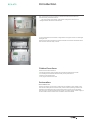
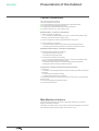
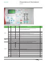
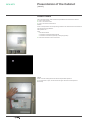
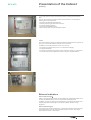
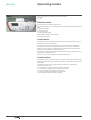
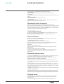
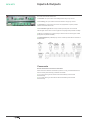
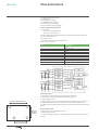
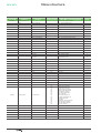
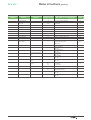
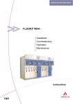
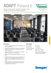
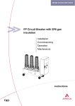
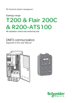
Medium Voltage Distribution RCX-ATS Automatic Transfer Switch-over unit vertical & horizontal RCX-ATS User Guide 6.0 www.schneider-electric.com RCX-ATS Contents ■ Introduction......................................................................................................... 3 □ Cabinet functions ........................................................................................... 3 □ Automation ..................................................................................................... 3 ■ Presentation of the Cabinet............................................................................... 4 □ Cabinet components ...................................................................................... 4 □ Man-Machine interface................................................................................... 4 □ Access levels ................................................................................................. 6 □ External indicators.......................................................................................... 7 ■ Operating modes ................................................................................................ 8 □ Remote mode................................................................................................. 8 □ Local mode..................................................................................................... 8 □ Local control ................................................................................................... 8 ■ Local operations ................................................................................................. 9 □ Operational rules for menus........................................................................... 9 □ Consultation menu ......................................................................................... 9 □ Test reset menu.............................................................................................. 9 □ Standard settings menu ................................................................................ 9 □ Settings menu ................................................................................................ 9 ■ Inputs & Outputs .............................................................................................. 10 ■ Faulty equipment .............................................................................................. 11 ■ Characteristics.................................................................................................. 12 ■ Fuses ................................................................................................................. 13 ■ Remote Signaling assignment table.............................................................. 13 ■ Menu structure.................................................................................................. 14 ■ Glossary ............................................................................................................ 16 2 ATS U.G. 6.0 RCX-ATS Introduction This User Manual covers the following versions of the RCX-ATS cabinet as manufactured by Schneider Electric: □ The vertical RCX-ATS cabinet, used for MV underground networks and designed for MV distribution switchboards. ■ The horizontal RCX-ATS cabinet, integrated into the upper section of a watertight switchgear unit. The RCX-ATS cabinet provides an interface between the two MV load-break switch FUs and their automatic relay controls. Cabinet functions The RCX-ATS cabinet allows to: ■ Switching between power supplies using the Source Switchover function ■ Controlling the load-break switches locally via the push buttons ■ Setting up the cabinet itself ■ Carrying out maintenance tests Automation Source Switch-over The Source Switch-over function is used when the supplies to a sub-station come from two MV cables (Source A & Source B). Under normal operating conditions the sub-station is supplied from just one of these sources. If there is a loss of voltage from this source, the Source Switchover function can switch the sub-station supply to the second MV cable if all switchover conditions have been fulfilled. ATS U.G. 6.0 3 RCX-ATS Presentation of the Cabinet Cabinet components The RCX-ATS cabinet comprises: ■ ■ ■ ■ ■ MV fault detection and warning MV voltage detection from the Functional Units’ Capacitive Dividers Energy unit, including batteries and charger The interface for the load-break switch control mechanisms Automation functions (i.e.: Source Switch-over). RCX-ATS cabinet — mechanical compartments ■ Upper compartment, containing: □ 4 x 12 V (7Ah) pre-cabled batteries in a pack, to ensure that the cabinet works correctly in case of a loss of the auxiliary supply. ■ Central compartment, with the cabinet’s Electronic Control Unit ■ Lower compartment, containing: □ The power supply unit with the fuse holder and the Safety Transformer □ The cabling zone, with cable glands and connectors to electrical controls RCX-ATS horizontal cabinet — mechanical compartments ■ Right hand side compartment, containing: □ The cabinet’s electronic control unit □ The cable zone with cable glands ■ Left hand side compartment, containing: □ 4 x 12 V (7Ah) pre-cabled batteries in a pack, to ensure that the cabinet works correctly in case of a loss of the auxiliary supply. □ The power supply unit with the fuse holder and the Safety Transformer □ Cabling zone with connectors to electrical controls The Electronic Control Unit includes the following functions: ■ Central Unit □ Provides a user-friendly Man-Machine Interface making it possible to customize the cabinet □ Ensure saving of the cabinet settings □ Includes the Source Switch-over function ■ Power Supply powers the whole cabinet from the main supply or from the battery backup source. ■ 2 command interfaces for electrical controls ■ 2 ammetric fault detectors Man-Machine interface The RCX-ATS cabinet has an enhanced, user-friendly, MMI which comprises a display, push buttons and LEDs. The display is a backlit LCD unit, with a 4 lines x 20 characters display. It remains off when operating temperatures are below -20°C or above +70°C 4 ATS U.G. 6.0 Presentation of the Cabinet RCX-ATS (contd.) Description of buttons and LEDs General buttons No Label (French) Label (English) 1 Dist./Local Remote/Local 2 Auto Auto Automation: Enable/Disable automatic switch over fonction L L/R RAZ Reset 4 CO Open Open order: opens the selected electrical control (in conjunction with the EU Validate button) L 5 CE Close Close order: closes the selected electrical control (in conjunction with the EU Validate button) L 6 Valid Selection of EU to open or close (in conjunction with OPEN/CLOSE) L Navigation through menus and scroll through parameter values L Validation of an action or selection L Cancel and action or return to previous menu L Equipment in standby mode: cabinet available (with periodic shutdown) L/R Equipment faulty: Cabinet unavailable (See Chapter 8) L/R Equipment in Remote: cabinet operating in remote mode R Equipment in Local: cabinet operating in local mode L Automation running: The Source Selection function is running L Automation non-operational: The Source Selection function is not running L Absence of auxiliary power supply (1): No mains voltage (1) L 48V supply available L Validate ◄, ►,▲,▼ 8 9 Esc 11 ATS U.G. 6.0 L/R 3 10 Information displayed Remote/Local mode: Changeover from remote to local (or the reverse). In Remote mode the MMI buttons are inactive. In Local mode the MMI buttons are active. Switch-off the external light Reset 48V protection fuse on 48V CT output Restart cabinet after 8 hours without Alternative power supply 7 Navigation controls Description OK OK ! in a red triangle 12 Dist. Remote 13 Local Local 14 En service Operating 15 Hors service Non-operational 16 ~ barred 17 48V 18 ~ barred A Absence of MV on EU A supply L 19 ~ barred B Absence of MV on EU B supply L 20 ~ barred Absence of auxiliary power supply (2): No mains voltage (2) (Redundant option) L 21 Green rectangle associated with load-break switch position Load-break switch OPEN L/R 22 Red rectangle associated with load-break switch position Load-break switch CLOSED L/R 23 Red rectangle associated with a symbol representing a torus (core) Ammetric fault current flow L/R 24 Padlock symbol Electrical control neutralised L 5 RCX-ATS Presentation of the Cabinet (contd.) Access levels There are three levels, used to define the possibilities for access to the cabinet: ■ Level 0: Free access ■ Level 1: Access for users ■ Level 2: Access for maintenance Level 0 Level 0 corresponds to normal operating conditions: all cabinet doors are closed and may be locked using padlocks. The operator can: View: □ MV network faults □ The status of the load-break switches □ The status of the cabinet (standby or faulty equipment) ■ Access the electrical control connectors Level 1 Level 1 access is designed for MV network responsible operators : ■ The main door is open, the two lower and upper doors are closed (Vertical RCX-ATS). 6 ATS U.G. 6.0 RCX-ATS Presentation of the Cabinet (contd.) ■ The right hand door is open and the left hand door is closed (Horizontal RCXATS). The user can change the operating mode: Local or Remote. In Local mode the following actions are authorised: ■ ■ ■ ■ ■ Operating the MV load-break switches, Starting or stopping the automation functions, Viewing of all light indicators, Activation of the RESET button, Basic configuration using the navigation buttons. Level 2 Level 2 is reserved to people in charge of installation and maintenance: All doors are open, and, on the Horizontal RCX-ATS the cover is removed. In addition to the access granted for Level 1, the user can: ■ ■ ■ ■ Access the fuse disconnector to turn on or off the Power Supply. Change the batteries, Intervene on all cabinet components: Fuses, electronic control unit, connections, Access the advanced configuration functions using the navigation buttons. External indicators External indicator light 1 Fitted on the outside of the cabinet, the red indicator light signals that at least one of the FUs has detected the flow of a over current fault current (MV Fault). In addition, the user can change the configuration to group several anomalies, thus, the general purpose indicator light can be used to indicate: MV fault + faulty equipment. External indicator light 2 The operator can choose from between 17 sources of information that can be used to light the indicator, thus, the general purpose indicator can show, for example: Source selection active + 230V absent. ATS U.G. 6.0 7 RCX-ATS Operating modes There are two operating modes for the RCX-ATS cabinet: ■ Remote ■ Local Remote mode In Remote mode, the cabinet is autonomous. The on-site operator can only observe the cabinet status using the following indicator lights: ■ Equipment Standby ■ Faulty equipment ■ Fault current flow ■ External indicator lights. All other LEDs information are turned off. The display remains off. Local mode The cabinet can only be changed to local mode by an operator physically in front of the cabinet (Press the LOCAL button). In Local mode the remote command to turn on or off the automation is disabled. The operator can control the load-break switches locally, turn on or off the Source Selection function, check the configuration of the cabinet and the operational data, configure cabinet operations, run internal tests, etc. The operator can switch the cabinet to Remote Mode from any Local Mode menu, by pressing the Local/Remote button. The LCD contrast can be adjusted using the ◄ and ►buttons. Local control The operator, from any local mode menus, can open or close a FU by simultaneously pressing the CO (or CE) button and the VALID button, corresponding to the FU to be manipulated. The open/close order will only be transmitted to the EU if all of the following conditions have been met: ■ ■ ■ ■ ■ 8 The command is contrary to the current position of the EU The batteries are capable of executing such a command The FU is capable of executing such a command Control has not been neutralized (no cabling faults) No Open/Close command already underway. ATS U.G. 6.0 RCX-ATS Local operations The main menu in Local Mode includes the following options: ■ Consultation: Display product information (faulty equipment, meters, measurements), ■ Test Reset: Used to carry out a test of the indicator (lights, fault detectors) and reset the counters to zero. ■ Standard Settings: Modify the basic configuration of the RCX-ATS. ■ Configuration: Access to various additional parameters (timing delays, assignment of indicator lights and remote commands, languages, etc.). Operational rules for menus The menus are organized hierarchically (See Organizational Flowchart). The menu options, each identified by a title, are listed vertically down the display screen. The ▲and▼ buttons are used to browse through the options. The button validates the selection and triggers the action proposed. The ESC button cancels the action underway and returns to the previous screen display. Consultation menu By selecting and validating the Consultation menu, the operator goes in a menu allowing him to check product information. The information displayed is listed, in detail, in the organizational flowchart. Test reset menu By selecting and validating the Test Reset menu, the operator goes in a menu allowing him to test the lights and detectors. ■ Lamp Light Test: Used to test all the leds ■ Detector Test: Select and test one of the fault detectors. Note: The batteries are tested cyclically. If a battery fault is detected the Faulty Equipment LED lights up and the 48V Present LED goes out. Lamp Test During the lamp test all LEDs are on. The test is stopped either by pressing the ESC button or by waiting one minute. Detector Test The Detector Test needs an AFD to be selected. The test is stopped either by pressing the ESC button or by waiting one minute. Testing the ammetric fault detector is a normal part of the processing of an ammetric fault. Standard settings menu By selecting the STD Setting menu, the operator enters a menu showing him, and allowing him to modify, the standard cabinet operating parameters. The modifiable parameters are listed, in detail, in the organizational flowchart. Operational rules for the setting of parameters Within the parameter menu, the parameters are listed vertically down the screen. For each parameter the display shows a single line with the description title and the current value. The▲ and ▼buttons are used to browse through the parameters. The button is used to select a parameter to modify. Its current value will appear on the line below. The ◄ and ► buttons are used to browse through the available values. The button is used to select the new value. The ESC button cancels the action underway and returns to the previous screen display. Validation of Modifications To validate the modification of one or more parameters, the operator must use the ESC button to return to the main menu. When changing view from the current menu to the main menu, the message Backup is displayed and the parameters are saved. Settings menu By validating the Settings option the operator brings up a menu used to modify additional parameters (timing delays, assignment of LEDs and Remote Signals, Languages, etc.) The information displayed is listed, in detail, in the organizational flowchart ATS U.G. 6.0 9 RCX-ATS Inputs & Outputs The RCX-ATS cabinet is fitted with: ■ Reset Ext.: An input used to acknowledge faults using a dry contact. ■ Ext. locking: An input used to lock the automation using a dry contact. ■ Client Unit: An input used to connect a unit (supplied as an option) used to transmit commands to the FUs. ■ Ext. Indicator Light 1 & 2 An output used to provide power to an external indicator light used to warn of various types of fault (assignment possible via MMI). ■ TS 1 to 7: (C/NO/NC dry contact) output: used to transmit various types of data (assignment is possible via MMI). ■ Faulty Equipment: (C/NO/NC) dry contact: used to provide data on the state of the RCX-ATS. Comments Resets with the Source Selection automation When the Source Selection automation system is running, the fault detectors are reset to standby if the following conditions are fulfilled: ■ For Line A: RPTI-type ‘MV Present‘ data transmitted by both FU A & B simultaneously. ■ For Line B: RPTI-type ‘MV Present‘ data transmitted by both FU A & B simultaneously 10 ATS U.G. 6.0 RCX-ATS Faulty equipment If the “Faulty Equipment“ LED is on (! In a red triangle), there is a fault on the equipment and the cabinet is not fully available. In this case, the Consultation/Faulty Equipment menu can be used to list the problems. The following table lists all causes of faulty equipment and the recommended methods to be used in resolving these problems. Faulty Equipment Table ATS U.G. 6.O Test displayed Description and recommendations Flt Charge Ae1 Charger 1 is faulty: ■ Disconnect and reconnect the cabinet ■ If the problem remains, contact your supplier Flt Charge Ae2 Charger 2 is faulty: ■ Disconnect and reconnect the cabinet ■ If the problem remains, contact your supplier Flt Rmt Fuse At least one battery is connected to an open circuit: ■ Check the condition of the two battery cable fuses ■ Check all connections between batteries and the power supply board ■ Change the batteries Battery Low The batteries need to be replaced or recharged, load break switches can no longer be manoeuvred: ■ Immediately charge the batteries ■ Immediately change the batteries Ram Corrupt The non-volatile system FRAM is faulty: ■ Disconnect and reconnect the cabinet ■ If the problem remains, contact your supplier Backup Prob The backup was not successful (your latest modifications have not been saved): ■ Repeat the modifications and the backup ■ If the problem remains, contact your supplier Incompl. Fua The positional feedback from FU A is incoherent: ■ Check the LV cabling from FU A ■ If the problem remains, contact your MV switchgear supplier Incompl. Fub The positional feedback from FU B is incoherent: ■ Check the LV cabling from FU B ■ If the problem remains, contact your MV switchgear supplier Timeout Fua The time taken to execute an operation on FU A is longer than normal: ■ Execute an operation on FU A ■ If the problem remains, check the cabling and maintenance of your MV switchgear or contact your MV switchgear supplier Timeout Fub The time taken to execute an operation on FU B is longer than normal: ■ Execute an operation on FU B ■ If the problem remains, check the cabling and maintenance of your MV switchgear or contact your MV switchgear supplier II Characteristics RCX-ATS ■ Auxiliary Power Supply: 230V ~ ■ Consumption: <50 VA (batteries charged) <80 VA (batteries not charged) <15 VA (absence of aux. power) ■ 48 V motor control supply voltage = Vertical and Horizontal RCX-ATS ■ Temperature: □ -15 to +55 °C when operating □ -25 to +70 °C when stored ■ Battery life:60 Open/Close operations for a Fluokit M24 type cubicle (Motor: 48 Vdc, 15 A-50 ms & 5 A-7s) ■ Protection: IP2X ■ Interface with the cubicle control mechanism (HAN, 10-pin connector): N° Function 1 0 Vdc 2 Close command 3 Open command 4 Open 5 Closed 6 +48 Vdc 7 Control neutralized 8 Presence/Absence of MV 9 Reserved 10 Reserved ■ General flow diagram Vertical RCX-ATS ■ Dimensions, without mountings: H 600 x W 298 x D 290 (mm) ■ Dimensions, with mountings: H 650 x W 298 x D 310 (mm) ■ Weight: Approx. 33 kg ■ Wall mounting: Using 4 x 10 mm diameter bolts or studs at a horizontal centre-tocentre distance of 250 mm and a vertical centre-to-centre distance of 631 mm. Centreline distance: 507 mm ■ Adapter used to attach the cabinet using an horizontal centre-to-centre distance of 560 mm Horizontal RCX-ATS Centreline distance 310 mm ■ Dimensions: H 285 x W 565 x D 395 (mm) ■ Weight: Approx. 33 kg ■ Cubicle mounting: Using the 4 x 10 mm diameter holes in the lower surface of the cabinet. Centreline distance : 340 mm 12 ATS U.G. 6.0 RCX-ATS Fuses ■ Auxiliary Power Supply: □ Fuse 10 x 38 □ The fuse rating is given on the label alongside the fuse holder: 2A gG ■ Batteries: □ 2 identical 5 x 20 fuses □ The fuse rating is given on the battery cables: 8A TT 125V ■ Electronic Control Unit: □ Re-arming fuse (RESET button) Remote Signaling assignment table Each remote signal and external indicator light can be assigned to one or more of the following pieces of information: ■ Ammetric fault — Line A ■ Ammetric fault — Line B ■ Absence MV-A (Yes/No) ■ Absence MV-B (Yes/No) ■ Pre-alarm A (Yes/No) ■ Pre-alarm B (Yes/No) ■ NC A (Yes/No) ■ NC B (Yes/No) ■ Local (Yes/No) ■ Auto. U/S (Yes/No) ■ Ext. Lock (Yes/No) ■ Cycle running (Yes/No) ■ No 230V AEI (Yes/No) ■ No 230V AEI (Yes/No) ■ No 48 V (Yes/No) ATS U.G. 6.0 I3 Menu structure RCX-ATS Level 1 Consultation Level 2 Meter Readings Test Reset Std Setting I4 Factory preset Min. Max. or list of options Units Fee Faulty Equipment table Phase Fault FU A No. of phase faults on FU A Phase Nr Fault FU A No. of near phase faults on FU A Earth Fault FU A No. of earth faults on FU A Earth Nr Fault FU A No. of earth near faults on FU A Manoeuvres FU A No. of manoeuvres on FU A Nr-Alarm FU A No. of near alarms on FU A Phase Fault FU B No. of phase faults on FU B Phase Nr Fault FU B No. of near phase faults on FU B Earth Fault FU B No. of earth faults on FU B Earth Nr Fault FU B No. of earth near faults on FU B Manoeuvres FU B No. of manoeuvres on FU B Nr-Alarm FU B No. of near alarms on FU B Int. Power Volt. General voltage V Temperature Cabinet temperature °C Batt. AE 1 AE1 battery voltage V Batt. AE 2 AE2 battery voltage (redundant option) V Lamp Test Testing lights and outputs Reset Resets all counters Test AFD A Test detector — FU A Test AFD B Test detector — FU B Max No. Abandons Switch Over Settings Level 3 Faulty Equipment 3 0 (inactive) 3 4 or 5 attempts A to B Yes Yes / No B to A Yes Yes / No No Confirm A + B No Yes / No In parallel No Supply Surge In parallel No Yes / No Auto. Delay Funct. No Yes / No Fault Duration 300 From 40 to 1000 in steps of 20 ms Phase Threshold 450 From I00 to 650 in steps of 50 A Earth Threshold 40 From 20 to 160 in steps of 5 A Telesig Assign Yes Yes No No No No No No No No No No No No No Fault Amp A (Yes/No) Fault Amp B (Yes/No) Absence MV A (Yes/No) Absence MV B (Yes/No) Pre Alarm A (Yes/No) Pre Alarm B (Yes/No) NC A (Yes/No) NC B (Yes/No) Local (Yes/No) Automation off (Yes/No) Ext. lock (Yes/No) Automat. running (Yes/No) No 230V AE1 (Yes/No) No 230V AE2 (Yes/No) No 48V (Yes/No) Conf Ext Indic I Conf Ext Indic 2 Idem Conf Rem Mon 1 Idem Conf Rem Mon 2 Idem Conf Rem Mon 3 Idem Conf Rem Mon 4 Idem Conf Rem Mon 5 Idem ATS U.G. 6.0 Menu structure (contd.) RCX-ATS Level I Level 2 Factory preset Min. Max. or list of options Units 10 1,2,3,4,5 ,10,20,30,40,50,60 S Pre. Man Time B 10 1,2,3,4,5 ,10,20,30,40,50,60 S Add. Delay 1000 50,100,200,500,1000,2000,30000, 4000,50000 Pulse Dur Rem A 2500 From 500 to 5000 in steps of 500 ms Pulse Dur Rem B 2500 From 500 to 5000 in steps of 500 ms Max Surv Time A 30 1,2,3,4,5,10,20,30,40,50,60 S Max Surv Time B 30 1,2,3,4,5,10,20,30,40,50,60 S Auto Time Delay 5 1,2,3,4,5,10,20,30,40,50,60 S Nor Time Delay 30 30,35,40,45,50,55,60 Near Fault T/Out 40 From 40 to 1000 in steps of 20 Timeout Reset 2 0,1,2,3,4,8,16,32,96 Inrush Timing 0 0(inactive),100,200,300,400,500,600 ,700,800,900,1000,1500, 2000,3000. Ivd Threshold 4 0,1,2,3,4,5,6,7 General Info ATS U.G. 6.0 Level 3 Pre. Man Time A Sel. Switch Option No Norm A Backup B Yes / No Sel. Switch Option No Norm B Backup A Yes / No Grouped Reset/ Setting AFD Yes Regroup Rst Yes / No Afd Setting / Line A Indep No LINE A INDEP Yes / No Afd Setting / Line B Indep No Line B Indep Yes / No Ic onfig No No Yes 8 (Yes/No) 16 (Yes/No) 8+8 (Yes/No) AE2 Option No Yes / No Setting IVD No No A integrated (Yes/No) B integrated (Yes/No) Ext Ind 1 Flashing Yes Ext Ind 1 Flashing Yes / No Ext Ind 2 Flashing Yes Ext Ind 2 Flashing Yes / No ms S ms H ms h 15 RCX-ATS 16 Glossary AE Power supply MMI Man-machine Interface ATS Automatic Transfer Switchover LED Light Emitting Diode LCD Liquid Crystal Display MV Medium Voltage PS Source Selection RCX Remote Control X TC Remote Order (Télécommande) TCD Double Remote Order (Télécommande Double) TS Remote-signaling (TéléSignalisation) FU Functional Unit (or cubicle) NC Load-break & disconnector switch IVD MV voltage detector VEXT External Light Indicator N/B Normal/Backup AFD Ammetric Fault Detector RPTI Voltage presence indicator relay Remote Mode = Controlled remotely ATS U.G. 6.0 Appendices ATS U.G. 6.0 Notes I7 ©2010 Schneider Electric - All rights reserved Schneider Electric 35, rue Joseph Monier CS 30323 92506 Rueil-Malmaison Cedex, France RCS Nanterre 954 503 439 Capital social 896 313 776 € www.schneider-electric.com ATS U.G. 6.0 As standards, specifications and designs change from time to time, please ask for confirmation of the information given in this publication. This document has been printed on ecological paper Publishing: Schneider Electric Design: Schneider Electric Printing: 11-2010