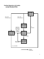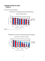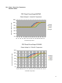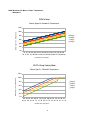
1
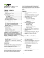
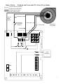
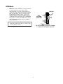
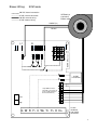
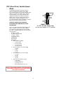
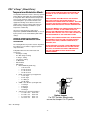
nrgMax
nrgMax
9103i
Advanced Universal Oil
Furnace Control
User's Guide
1
nrgMax
nrgMax
9103i Advanced Universal
Oil Furnace Control
Table of Contents
OVERVIEW....................................................................2
Features....................................................................2
Optional Advanced Features....................................2
SPECIFICATIONS.........................................................5
Terminals and Connections:.....................................5
Low Voltage:........................................................5
Line Voltage:........................................................5
Burner Connections:............................................6
Status LED Flashing Patterns .................................6
SETTING OPTIONS WITH JUMPER.......................6
OPERATIONAL MODES:..............................................8
Standard PSC (Direct Drive) Mode........................10
Enhanced PSC (Direct Drive) Mode ......................10
ECM Mode: ............................................................12
PSC (Direct Drive) Variable Speed Mode: ............14
PSC “eTemp” (Direct Drive) TemperatureModulation Mode: ..................................................16
PWM “eTemp” Temperature-Modulation Mode: .. .20
BURNER CONNECTIONS..........................................22
Riello, Standard......................................................22
Riello, Post-purge...................................................22
Riello, with Post-purge module...............................22
Beckett/Carlin (no post-purge)...............................23
Beckett/Carlin (no post-purge) Optional method ...23
Beckett/Carlin with Post Purge (Alternate).............24
Standard PSC Heating & Cooling Sequences............25
Heating Sequence (all mode except Standard PSC). .26
Cooling Sequence (all modes except Standard PSC) 27
VARIABLE SPEED BLOWER CHARTS......................28
PSC Direct Drive Variable Speed Mode:................28
PWM (Brushless DC -Motor) Variable Speed Mode:
................................................................................28
PSC “eTemp” (Direct Drive) TemperatureModulation Mode: ..................................................29
PWM (Brushless DC Motor)“eTemp” TemperatureModulation:.............................................................30
The control is suitable for use with Direct-Drive PSC motors
and ECM motors. ECM motors can be controlled in the
common “thermostat-mode” or with other innovative and
optional methods. PSC motors are controlled with traditional
heavy-duty relay outputs, but can also be controlled in a
variable speed method using the optional low-cost plug-in
adaptor.
Features
•
•
•
•
•
•
•
•
•
•
Industry-standard footprint, mounting and
connections
compatible with American burners (Beckett, Carlin
etc) as well as Riello Burners with no additional
relays required
Industry-standard 9-pin burner connection
120VAC Connections for:
◦ Heat (Speed 1) motor winding
◦ Cool (Speed 2) motor winding
◦ Electronic Air Cleaner (EAC)
◦ Humidifier
◦ Continuous Fan
24VAC Thermostat Connections for:
◦ 5-wire (R,C,W,Y,G), plus
◦ W2 (Stage 2 Heating)
◦ Y2 (Stage 2 cooling)
◦ Yx (dummy connection)
◦ O/B (Heat Pump reversing valve)
◦ DH (Dehumidification)
16-pin connection to GE/Beloit-style ECM Motors
LED Status indicator
Solid-State resettable fuse for 50VA Transformer
protection
Double-sided Copper-clad PC board, soldered top
and bottom for optimum strength, rigidity and
durability
Multipurpose DIP-switch for field settings
Optional Advanced Features
•
•
•
•
OVERVIEW
•
The nrgMAX 9103i is the only oil-furnace control you will ever
need. It is a feature-rich control designed to meet the needs
of modern energy-efficient oil furnaces while still offering
backwards compatibility with legacy products.
Mounting in the industry-standard footprint with familiar layout
and connections this high quality design meets the needs of
an entire industry sector. It eliminates the need for additional
controls to accommodate Euro-style burners, and offers an
array of variable speed options to suit any requirement.
•
•
2
Enhanced operation of Standard Direct-Drive PSC
Blowers
Variable speed control of traditional PSC blower
motors with plug-in module
Variable speed control of alternate ECM (Brushless
DC) motors using PWM signal
Variable speed based on DIP-switch Settings or
optional plug-in plenum temperature sensor
Data-port to allow PC communication to view:
◦ Status
◦ Plenum temperature
◦ Thermostat inputs
◦ Limit string status
◦ Burner status
◦ DIP-switch Settings:
Alternate Burner Connection (for burners with postpurge capability)
Automatic dehumidification
Features
120VAC Mains
Supply
connections
120VAC Neutral Burner 9-pin
Connections
connector
Humidifier
Connection
(120VAC)
Alternate Burner
connection with
continuous
120VAC
Terminals for
unused blower
wires
120VAC outputs
to loads and
accessories
Built-in burner
supply relay
(powers limit
string and burner)
Heavy duty relays
power blowers up
to 15Amps
2-D Scan code for
rapid access to this
user document online
via smart-phones
Data Port for
Windows® PC
diagnostics and
troubleshooting
24VAC Transformer
input connection.
Protected by Solidstate resettable fuse
Field-selectable
option jumpers
16-pin connector
for ECM Motors
Plug-in port for
Optional supply
air temperature
sensor
Multipurpose
Dip-switch for
user settings
Plug-in port for
variable speed
control of optional
motors
Industry-Standard
mounting holes
and footprint
Standard 5-wire
thermostat
connections
Extended
thermostat
connections
Bright LED for
status indication
Patents Pending
3
◦
SPECIFICATIONS
•
•
•
Electrical Ratings:
◦ Power Requirements:
▪ Voltage: 24Vac, 50/60 Hz.
▪ Current: 4 VA at 24 Vac.
▪ PTC Fuse (resettable) trips at 4.5A
◦ Contact Ratings:
▪ Circulating Fan: 15A Full Load, 30A Locked
Rotor at 115 Vac (includes optional EAC
load).
▪ Burner: 5.8 A Continuous Load (7.4A with
interrupted ignition)
Settings: Standard Configuration
◦ Heating:
▪ Blower On Delay: 30 seconds, fixed.
▪ Blower Off Delay (BOD): 90, 120, 150, 180
seconds, field-adjustable.
◦ Timing Tolerance: less than 1 second
Environmental Ratings:
◦ Temperature: -40 to +150° F [-40° to +66° C].
◦ Humidity: 95% maximum, non-condensing.
Terminals and Connections:
◦
Line Voltage:
•
•
•
•
•
•
•
•
•
•
•
•
•
Thermostat:
◦ G:
Blower On
◦ W:
Call for heat (0.08A load)
◦ R:
24VAC out to thermostat
◦ Y1:
Cooling, Stage 1
◦ C:
24VAC common
◦ W2:
Heating, Stage 2
◦ Y2:
Cooling, Stage 2
◦ Yx:
Dummy terminal, no connection
◦ O:
Heat pump reversing valve
◦ DH:
Dehumidification
Snsr:
Plenum Temperature Sensor (Thermistor,
5Kohm @ 25°C (77°F). (Optional)
Vsp:
Pulse-Width-Modulation (PWM) output to
alternate variable speed motors.
◦ Brushless DC (BLDC) Mode: 0-5VDC, 80Hz,
0-100% with 0.4% resolution
◦
•
•
•
•
•
Triac Mode: 60Hz Phase Modulation, ≈70-100%
with 5% resolution (Use with triac module)
CLASS 2 TRANSFORMER 50VA Max (overload
protected)
◦ X:
24VAC
◦ C
24VAC Common
16-PIN ECM Connector: Convenient interface
between 10-position thermostat, DIP-switches and
ECM motors.
Data Port:
Edge connect to communication
adapter
Option Jumpers: Selectable Options:
Unused: No connection (2 terminals)
L1:
120VAC 60Hz, 1ph, 15 A mp (Max) supply
N:
120VAC Neutral supply
Neutrals: Connection points for loads, tied internally
to N (6 terminals)
120VAC : L1 supply to accessories, continuously
powered (3 terminals)
Cont.
120VAC to Continuous speed of blower.
Normally energized, it is de-energized whenever
Cool or Heat terminals are energized
EAC:
120VAC to Electronic Air Cleaner.
Energized along with Cool or Heat terminals
Heat-Spd1:
120VAC 15A, 1HP blower speed.
Cool-Spd2:
120VAC 15A, 1HP blower speed
H:
120VAC 1A to Humidifier. Powered by
burner motor feedback (Pins 7-8 on 9-pin burner
connector).
Burner Connections:
Low Voltage:
•
F1 Variable Speed PSC Direct Drive Mode (for
use with ACC001 PSC Speed Module)
F2: Enhanced PSC Direct Drive Mode:
9-PIN AMP Connector:
(MATES WITH TYCO PART #350720)
1) Safety Limit string (return)
2) 120VAC to Oil Burner (high-limit protected)
3) Burner T-T (internally connected to Pin 6)
4) Neutral (internally connected to Pin5 and N)
5) Neutral (internally connected to Pin 4 and N)
6) Burner T-T (internally connected to Pin 3)
7) Burner Motor (internally connected to Pin 8)
8) Burner Motor (internally connected to Pin 7)
9) 120VAC to Safety Limit string. Normally off,
energized on call for heat by Relay K1
Edge Connector (Alternate, 6 conductor) mates with
Molex 09-01-6061.
◦ Motor: Burner Motor
◦ Limit: 120VAC to Safety Limit string. Normally
off, energized on call for heat by Relay K1
◦ Limit: Safety Limit string (return)
◦ L1:
120VAC to Oil Burner (high-limit
protected)
◦ 120V: 120VAC Continuous (not limit
protected)INSTALLATION
When Installing this Product...
1. Read these instructions carefully. Failure to follow them
could damage the product or cause a hazardous
condition.
2. Check the ratings and specifications given in the
Instructions and on the product to assure the product is
suitable for your application.
3. Installer must be a trained, experienced service
technician.
4. After installation is complete, check out the product
operation as provided in these instructions.
4
CAUTION
Disconnect power supply before wiring to prevent
electrical shock or equipment damage.
Location and Mounting
The 9103i is mounted in the appliance wiring
compartment using four No. 6 screws (obtained locally)
through standoffs on the corners of the board.
is used in PSC or BLDC Variable Speed Modes the
control immediately recognizes it and will begin to
adapt the variable speed operation to Temperature
Modulation Mode. If the sensor is unplugged at any
time the control reverts back to normal Variable
Speed Mode.
Wiring
All wiring must comply with local codes and ordinances.
Disconnect power before making wiring connections.
Setting Options
Status LED Flashing Patterns
Standby
1
sec
1
sec
1
sec
Heating
jumper
NO
OPTIONS
SELECTED
F1
F2
Cooling
F3
Hi Limit
Limit reset
No Burner
SETTING OPTIONS WITH JUMPER
The Option Jumper Pins are located beside the
micro-controller chip, above the thermostat G
terminal. The factory-default has the jumper in the
upper-most position indicating Standard operation
(No options enabled). Position F1 enables the
variable speed PSC option. F2 enables the
Enhanced PSC (Direct Drive) features.
F3 is reserved for OEM-specific customization. See
OEM furnace guide for details of this feature.
PSC-Variable F1
Speed Mode
F2
F3
PSC
Enhanced
Mode
F1
F2
F3
OPERATIONAL MODES:
All operational modes are simultaneously active on
the 9103i, and the user needs only to make the
appropriate connections to make use of them. The
DIP-Switch is interpreted by the on-board software
differently for each mode of operation.
Custom
Furnace-OEM
Program
F1
F2
F3
Whenever the optional plenum temperature sensor
5
Speed (Speed2/Cool Speed)
Standard PSC (Direct Drive) Mode
•
•
Blower motor is driven by on-board heavy duty
relays. Heat, Cool and Continuous speeds are
available from 0.250” male spade terminals clearly
marked on board. Compatible with all 5+ wire
thermostats and responds to:
◦ W: heating
◦ Y1: cooling
◦ Y2: cooling
◦ G: Blower On
◦ DIP-Switch:
▪ Blower Off Delay (BOD):
•
A: 90 Seconds
•
B: 120 Seconds
•
C: 150 Seconds
•
D: 180 Seconds
▪ Heat: no function
▪ Cool: no function
▪ Adj: no function
jumper
NO
OPTIONS
SELECTED
NOTE: FOR 2-STAGE COOLING IN ENHANCED
MODE USE YX AND Y2. YX IS A DUMMY
TERMINAL AND IS IGNORED BY THE CONTROL
LOGIC BUT PROVIDES A CONVENIENT
CONNECTION POINT FOR THE AC
COMPRESSOR. WHEN THE THERMOSTAT
CALLS FOR STAGE 1 COOLING (A Y1 SIGNAL
FROM THE THERMOSTAT) IT IS TERMINATED
AT YX, BUT THE THERMOSTAT ALSO
ACTIVATES G SIMULTANEOUSLY. THE 9103I
THEN ENERGIZES THE LOWER SPEED HEAT
TERMINAL AS LONG AS THE CONDITION
EXISTS. IF Y2 IS ENERGIZED (TOGETHER WITH
Y1/G, OR SEPARATELY) THE CONTROL WILL
SWITCH TO THE HIGHEST SPEED. THIS
ALLOWS FOR 2 DIFFERENT BLOWER SPEEDS
FOR 2-STAGE COOLING
F1
F2
F3
Option Jumper
For Standard PSC Direct Drive
mode ensure that Jumper is in
default “No-Option” position
Enhanced PSC (Direct Drive) Mode
Selected by placing the option jumper across
position # F2 on the Option Select pins (See “Setting
Options”). All wiring and connections remain the
same as the Standard PSC mode, however the
operation is enhanced.
ATTENTION:
ENABLE THIS OPTION ONLY WHEN THE COOLSpd 2 TERMINAL IS CONNECTED TO A HIGHER
BLOWER SPEED THAN HEAT-Spd1 OUTPUT.
jumper
F1
F2
EXAMPLE:
“HEAT-Spd1” CONNECTED TO MEDHIGH
“COOL-Spd2” CONNECTED TO HIGH
•
Cooling: Blower is initially started on Lower
Speed for 4 minutes to allow for
dehumidification, after which the blower
switches to Higher Speed. If the the 24VAC
signal to the DH terminal opens this signals
a call to dehumidify and the blower drops
down to Lower Speed to encourage greater
condensation across the cooling coil. When
the 24VAC signal reappears on DH the
blower is switched back up to Higher Speed
◦ Y1 (24V signal): 4 minutes at Lower
speed to dehumidify, then to Higher
speed
◦ DH (NO 24V signal): immediately
drops from Higher speed to Lower
speed to dehumidify.
◦ DH (24V signal returns): Blower
stepped up to Higher Speed
◦ Y2 (24V signal) overrides DH and Y1
keeping Higher Speed energized as
long as signal on Y2 is present
◦ G (24V signal alone without Y1, Y2, or
W): energizes Lower Speed terminal
F3
Option Jumper
For Enhanced PSC Direct Drive
mode ensure that Jumper is in F2
position
Heating:
◦ W (24V signal) activates Lower Speed
(Speed1/Heat Speed) output
◦ W+W2 (24V signals) activate Higher
6
Blower Wiring:
Standard and Enhanced PSC (Direct Drive) Modes
120 VAC internal connection
24 VAC internal connection
120 VAC external wiring
24 VAC external wiring
Unused
Motor
Speed
Continuous speed
Continuous
Fan Switch
(Optional)
Heat speed
Multi-Speed
PSC Blower
Cool speed
Neutral
N
4
1
Spare
7
8
Cool
Heat
EAC
Cont
2
3
6
X
C
9
BURNER (Alternate)
L1
24 VAC
Transformer
Snsr
Vsp
G W R Y1 C W2 Y2 YX O DH
7
ECM Mode:
•
ECM Motor handles all blower speed logic in factoryset “thermostat mode” and it monitors all ten
thermostat inputs. The 9103i control continues to
energize the Burner, EAC and H terminals normally.
While the DIP-Switch settings are now directed to
the ECM motor through the 16-pin connector the
9103i will continue to interpret the BOD settings to
establish the delay period before de-energizing EAC
terminal. Please note that the OEM factory -settings
for the ECM blower-off delay may not co-ordinate
with the EAC delay.
jumper
NO
OPTIONS
SELECTED
F1
F2
F3
THE 9103I CONTROLLER HAS NO INFLUENCE
OVER THE ECM MOTOR AS ALL SIGNALS ARE
“PASS-THROUGH” ONLY.
Option Jumper
For ECM mode ensure that Jumper
is in default “No-Option” position
8
Blower Wiring:
ECM mode
120 VAC internal connection
24 VAC internal connection
GE/Beloit (or
equivalent)
Blower motor
120 VAC external wiring
24 VAC external wiring
120VAC (L1)
Neutral
N
4
1
Spare
7
8
Cool
Heat
EAC
Cont
2
3
6
X
C
9
BURNER (Alternate)
L1
24 VAC
Transformer
16-pin AMP Connector
(internally connected to all
points on Dip-switch and
thermostat terminals)
Snsr
Vsp
G W R Y1 C W2 Y2 YX O DH
16-wire
conductor
and mating
connectors
9
PSC (Direct Drive) Variable Speed
Mode:
A compatible Direct Drive PSC blower motor is
driven by optional plug-in ACC001 PSC Motor
Speed Control Module in conjunction with Dip-switch
settings. Heat and Cool outputs on the 9103i are
routed through the speed control module to the
appropriate windings on the blower motor. The
module reduces the line voltage delivered to the
blower thereby slowing according to the userselectable Dip Switch settings allowing fine-tuning of
blower speed in Heat and Cool operation.
jumper
F1
F2
F3
REFER TO SPEED CURVES FOR MORE
INFORMATION ON TEMPERATURE-SPEED
RELATIONSHIP
Option Jumper
For PSC Variable Speed mode
ensure that Jumper is in F1 position
Speeds are derived from DIP-switch settings (SEE
. A jumper must be placed on the Option
selector pins by connecting Pin 2 and 3 to enable
this feature. Compatible with all 5+ wire thermostats
and responds to:
◦ W: Stage1 heating
◦ W + W2: Stage 2 heating
◦ Y: Stage 1 cooling
◦ Y2: Stage 2 cooling
◦ G: Blower On
◦ Dehumidistat
◦ DIP-Switch:
▪ Blower Off Delay (BOD):
•
A: 90 Seconds
•
B: 120 Seconds
•
C: 150 Seconds
•
D: 180 Seconds
▪ Heat: (Sets blower speed in heating)
•
A: 100%
•
B: 90%
•
C: 80%
•
D: 70%
▪ Cool: (Sets blower speed in cooling)
•
A : 100%
•
B : 90%
•
C : 80%
•
D : 70%
▪ Adj: (Fine tunes blower speeds)
•
A No adjust
•
B Heat speed -5%
•
C Cool speed - 5%
•
D Heat and Cool speeds - 5%
NOTE 1)
NOTE 1: TRIAC SPEED CONTROL OF PSC MOTORS IS
APPROXIMATE. THEREFORE FRACTIONAL POWER
AND SPEED IS ESTIMATED.
10
Multi-Speed
PSC Blower
Blower Wiring: PSC Variable Speed Mode
120 VAC internal connection
24 VAC internal connection
120 VAC external wiring
24 VAC external wiring
Neutral
Unused Motor Speeds
Lower
Speed
Higher
Speed
ACC001
PSC Speed
Control Module
120VAC
N
4
1
Spare
7
8
Cool
Heat
EAC
Cont
2
3
6
X
C
9
BURNER (Alternate)
L1
24 VAC
Transformer
Snsr
Vsp
G W R Y1 C W2 Y2 YX O DH
11
PSC “eTemp” (Direct Drive)
Temperature-Modulation Mode:
A compatible PSC blower motor is driven by optional
plug-in ACC001 PSC Motor Speed Control Module
in conjunction with a ACC003 Plenum Temperature
Sensor. Heat and Cool outputs on the 9103i are
routed through the speed control module to the
appropriate windings on the blower motor. The
module reduces the line voltage delivered to the
blower thereby slowing it to maintain a speedtemperature relationship.
Speeds are derived from the delivered air
temperature (TARGET TEMPERATURE) as sensed
by the plenum sensor and modified by DIP-switch
settings.
REFER TO SPEED CURVES FOR MORE
INFORMATION ON TEMPERATURE-SPEED
RELATIONSHIP
The Heating blower off period is not time dependent,
but continues to run until the supply temperature
drops below 90 F.
Compatible with all 5+ wire thermostats and
responds to:
◦ W: Stage1 heating
◦ W + W2: Stage 2 heating
◦ Y: Stage 1 cooling
◦ Y2: Stage 2 cooling
◦ G: Blower On
◦ Dehumidistat
◦ DIP-Switch:
▪ Blower Off Delay (EAC only)
•
A: 90 Seconds
•
B: 120 Seconds
•
C: 150 Seconds
•
D: 180 Seconds
▪ HEAT- 100% blower speed applied at:
•
A: 150 deg F
•
B: 156 deg F
•
C: 162deg F
•
D: 168 deg F
▪ COOL- 100% blower speed applied at:
•
A: 34deg F
•
B: 40deg F
•
C: 46deg F
•
D: 52deg F
▪ Adj: Fine tunes target temperatures
•
A: Heat= N/C* Cool= N/C*
•
B: Heat= +5F
Cool= N/C
•
C: Heat= N/C* Cool= -3F
•
D: Heat= +5F
Cool= -3F
TARGET TEMPERATURES ARE A REFERENCE POINT
ON THE SPEED-TEMPERATURE CURVE WHERE THE
BLOWER IS SET TO OPERATE AT 100% FULL LINE
VOLTAGE.
UNDER NORMAL CIRCUMSTANCES THE BLOWER
WILL FIND A STEADY-STATE HEATSPEED AT A
TEMPERATURE LOWER THAN THE TARGET, AND FIND
A STEADY-STATE COOL SPEED AT A TEMPERATURE
HIGHER THAN THE COOLING TARGET TEMPERATURE.
IN COOLING MODE A LOW TEMPERATURE LIMIT OF 45
DEGREES F IS FIXED. IF THE PROBE DETECTS A
CHILLED AIR TEMPERATURE BELOW THIS LIMIT THE
BLOWER WILL RECIEVE 100% FULL LINE VOLTAGE TO
PREVENT DAMAGE TO THE COOLING SYSTEM.
STEADY STATE TEMPERATURES WILL BE DEPENDENT
ON VARIABLES SUCH AS LINE VOLTAGE, BLOWERDESIGN, DUCT WORK, BURNER FIRING-RATE, AC
TONNAGE, ETC.
AFTER REACHING A STEADY STATE TEMPERATURE
THE INSTALLER SHOULD ADJUST THE DIP-SWITCH
SETTINGS TO ACHIEVE THE IDEAL TEMPERATURE
FOR THE EQUIPMENT IN BOTH HEATING AND
COOLING MODES
jumper
F1
F2
F3
Option Jumper
For PSC Variable Speed mode
ensure that Jumper is in F1 position
* N/C = No Change
12
Multi-Speed
PSC Blower
Blower Wiring: eTemp Variable Speed PSC
120 VAC internal connection
24 VAC internal connection
120 VAC external wiring
24 VAC external wiring
Neutral
Unused Motor Speeds
Lower
Speed
Higher
Speed
ACC001
PSC Speed
Control Module
120VAC
N
4
1
Spare
7
8
Cool
Heat
EAC
Cont
2
3
6
X
Optional
Temperature
Sensor
# ACC003
C
9
BURNER (Alternate)
L1
24 VAC
Transformer
Snsr
Vsp
G W R Y1 C W2 Y2 YX O DH
13
PWM Variable Speed Mode:
A compatible BLDC (Brushless DC) Blower Motor is
driven by a 0 to 5Vdc 80Hz Pulse-width modulated
signal from Vsp terminal from 0 to 100% duty cycle,
representing 0 to 100% full power to the motor.
jumper
F1
F2
Heat, Cool and Continuous speeds are all derived
using this method. Speeds are derived from DIPswitch settings (SEE NOTE 2) . This features is always
enabled if there is no option jumper required.
F3
REFER TO SPEED CURVES FOR MORE
INFORMATION ON TEMPERATURE-SPEED
RELATIONSHIP
Option Jumper
For PWM Variable Speed mode for
Brushless DC motor ensure that
Jumper is in default “no option”
position
Compatible with all 5+ wire thermostats and
responds to:
◦ DIP-Switch
◦ W: Stage1 heating
◦ W + W2: Stage 2 heating
◦ Y: Stage 1 cooling
◦ Y2: Stage 2 cooling
◦ G: Blower On
◦ Dehumidistat
◦ DIP-Switch:
▪ Blower Off Delay (BOD):
•
A: 90 Seconds
•
B: 120 Seconds
•
C: 150 Seconds
•
D: 180 Seconds
▪ Heat: (Sets blower speed in heating)
•
A: 30%
•
B: 50%
•
C: 70%
•
D 90%
▪ Cool: (Sets blower speed in cooling)
•
A 65%
•
B 75%
•
C 85%
•
D 95%
▪ Adj: (Fine tunes blower speeds)
•
A No adjust
•
B Heat speed -10%
•
C Cool speed - 5%
•
D Heat -10% AND Cool -5%
NOTE 2: FAILURE TO PROPERLY INSTALL THE OPTION
SELECTOR PINS MAY RESULT IN ERRATIC RESPONSE
FROM THE BLDC MOTOR
14
Blower Wiring:
PWM BLDC (Brushless DC Motor) mode
Brushless DC
Motor with PWM
Speed Control
(0-5VDC, 80Hz)
120 VAC internal connection
24 VAC internal connection
120 VAC external wiring
24 VAC external wiring
120VAC (L1)
Neutral
N
4
1
Spare
7
8
Cool
Heat
EAC
Cont
2
3
6
X
C
9
BURNER (Alternate)
L1
24 VAC
Transformer
Snsr
Vsp
G W R Y1 C W2 Y2 YX O DH
15
PWM “eTemp” TemperatureModulation Mode:
A compatible BLDC Blower Motor is driven by a 0 to
5Vdc 80Hz Pulse-width modulated signal from Vsp
terminal from 0 to 100% duty cycle, representing 0 to
100% full power to the motor in conjunction with a
plenum temperature sensor.
Speeds are derived from the delivered air
temperature as sensed by the plenum sensor and
modified by DIP-switch settings.
REFER TO SPEED CURVES FOR MORE
INFORMATION ON TEMPERATURE-SPEED
RELATIONSHIP
The blower off period is not time dependent, but
continues to run until the supply temperature drops
below 90 F.
Compatible with all 5+ wire thermostats and
responds to:
◦ W: Stage1 heating
◦ W + W2: Stage 2 heating
◦ Y: Stage 1 cooling
◦ Y2: Stage 2 cooling
◦ G: Blower On
◦ Dehumidistat
◦ DIP-Switch:
▪ Blower Off Delay (EAC only)
•
A: 90 Seconds
•
B: 120 Seconds
•
C: 150 Seconds
•
D: 180 Seconds
▪ HEAT- 100% blower speed applied at:
•
A: 140 deg F
•
B: 150 deg F
•
C: 160 deg F
•
D: 170 deg F
▪ COOL- 100% blower speed applied at:
•
A: 55 deg F
•
B: 49 deg F
•
C: 43 deg F
•
D: 37 deg F
▪ Adj: Fine tunes target temperatures
•
A: Heat= N/C* Cool= N/C*
•
B: Heat= +5F
Cool= N/C
•
C: Heat= N/C* Cool= -3F
•
D: Heat= +5F
Cool= -3F
TARGET TEMPERATURES ARE A REFERENCE POINT
ON THE SPEED-TEMPERATURE CURVE WHERE THE
BLOWER IS SET TO OPERATE AT 100% FULL SPEED.
UNDER NORMAL CIRCUMSTANCES THE BLOWER
WILL FIND A STEADY-STATE HEATSPEED AT A
TEMPERATURE LOWER THAN THE TARGET AND FIND
A STEADY-STATE COOL SPEED AT A TEMPERATURE
HIGHER THAN THE COOLING TARGET TEMPERATURE
IN COOLING MODE A LOW TEMPERATURE LIMIT OF 45
DEGREES F IS FIXED. IF THE PROBE DETECTS A
CHILLED AIR TEMPERATURE BELOW THIS LIMIT THE
BLOWER WILL OPERATE AT 100% FULL SPEED TO
PREVENT DAMAGE TO THE COOLING SYSTEM.
STEADY STATE TEMPERATURES WILL BE DEPENDENT
ON VARIABLES SUCH AS BLOWER-DESIGN, DUCT
WORK, BURNER FIRING-RATE, AC TONNAGE, ETC.
AFTER REACHING A STEADY STATE TEMPERATURE
THE INSTALLER SHOULD ADJUST THE DIP-SWITCH
SETTINGS TO ACHIEVE THE IDEAL TEMPERATURE
FOR THE EQUIPMENT IN BOTH HEATING AND
COOLING MODES
jumper
F1
F2
F3
Option Jumper
For PWM Variable Speed mode for
Brushless DC motor ensure that
Jumper is in default “no option”
position
* N/C = No Change
16
Blower Wiring: PWM eTemp BLDC Temperature Modulation Mode
Brushless DC
Motor with PWM
Speed Control
(0-5VDC, 80Hz)
120 VAC internal connection
24 VAC internal connection
120 VAC external wiring
24 VAC external wiring
120VAC (L1)
Neutral
N
4
1
Spare
7
8
Cool
Heat
EAC
Cont
2
3
6
X
Optional
Temperature
Sensor
#ACC003
C
9
BURNER (Alternate)
L1
24 VAC
Transformer
Snsr
Vsp
G W R Y1 C W2 Y2 YX O DH
17
BURNER CONNECTIONS
Riello, with Post-purge module
Riello, Standard
1
4
7
2
5
8
3
6
9
Other safety
devices as
required
Limit Control
Oil Burner Primary Safety
Control
N
L 7
Burner
Motor
Riello, Post-purge
Oil Burner Primary
Safety Control
Post purge
Module
Burner (Alternate)
N
L
7
Burner Motor
Limit String
120V (Limit Protected)
Neutral
1
120V (Continuous)
Molex # 09-01-6061
18
Burner
Motor
Beckett/Carlin (no post-purge)
1
4
7
Other safety
devices as
required
2
5
8
Limit Control
3
6
9
Oil Burner Primary
Safety Control
T T L1
N
Orange
Burner
Motor
Beckett/Carlin (no post-purge)
Optional method
1
4
7
Other safety
devices as
required
2
5
8
Limit Control
3
6
9
Oil Burner Primary
Safety Control
T T L1
N
Orange
Burner
Motor
19
Beckett/Carlin with Post Purge
(Alternate)
T
T
Oil Burner Primary
Safety Control
Burner (Alternate)
Motor Limit
Burner Motor
Limit String
120V (Limit Protected)
Neutral
1
120V (Continuous)
Burner
Motor
Molex # 09-01-6061
20
N
L1
Standard PSC Heating & Cooling
Sequences
Standby
Burner=OFF
Blower=OFF
CALL FOR
HEAT ON W
Y1, Y2
or G
Circulate
Burner=OFF
Blower=COOL
Timer=OFF
CALL FOR
HEAT ON W
BURNER DETECTED
Pre-Heat BURNER NOT
Burner=Enabled DETECTED
Blower=OFF
Timer=30Sec
Burner=OFF
Blower=HEAT
Timer=BOD
BURNER DETECTED
LIMIT CLOSED
High Limit
Burner=Enabled
Blower=HEAT
Timer=OFF
No Ignition
Burner=Enabled
Blower=OFF
Timer=OFF
Heat-1
LIMIT OPEN Burner=Enabled
Blower=HEAT
Timer=OFF
BURNER NOT
DETECTED
TIMER EXPIRES
Limit-Reset
Lost Flame
Burner=Enabled
Blower=HEAT
Timer=BOD
NORMAL SEQUENCE
W CLEARS
ABNORMAL SEQUENCE
Post-Heat
Burner=OFF
Blower=HEAT
Timer=BOD
21
Heating Sequence (all mode
except Standard PSC)
Standby
Burner=OFF
Blower=OFF
CALL FOR
HEAT ON W
G
ALONE
Circulate
Burner=OFF
Blower=HEAT
Timer=OFF
CALL FOR
HEAT ON W
BURNER DETECTED
Pre-Heat BURNER NOT
Burner=Enabled DETECTED
Blower=OFF
Timer=30Sec
Burner=OFF
Blower=HEAT
Timer=BOD
No Ignition
Burner=Enabled
Blower=OFF
Timer=OFF
BURNER DETECTED
LIMIT CLOSED
High Limit
Burner=Enabled
Blower=HEAT
Timer=OFF
BURNER NOT
DETECTED
Heat-1
LIMIT OPEN Burner=Enabled
Blower=HEAT
Timer=OFF
W2 IS
ENERGIZED
TIMER EXPIRES
Limit-Reset
Lost Flame
Burner=Enabled
Blower=HEAT
Timer=BOD
BURNER NOT
Heat-2
Burner=Enabled DETECTED
Blower=COOL
Timer=OFF
LIMIT OPEN
W CLEARS
NORMAL SEQUENCE
Post-Heat
Burner=OFF
Blower=HEAT
Timer=BOD
ABNORMAL SEQUENCE
22
Cooling Sequence (all modes
except Standard PSC)
Standby
Burner=OFF
Blower=OFF
CALL FOR
COOLING ON Y1
CALL FOR
COOLING ON Y2
PRE-COOL
Blower=HEAT
Timer=240Sec
COOL-2
Burner=Enabled
Blower=COOL
Timer=OFF
SWITCHES
BETWEEN
COOL 1 AND
COOL 2
ACCORDING
TO Y2
Y1
CLEARS
COOL-1
Blower=COOL
Timer=OFF
DH CLEARS
Dehumidify
DH
ENERGIZED
Blower=HEAT
Timer=OFF
Y1 & Y2 CLEAR
NORMAL
SEQUENCE
23
VARIABLE SPEED BLOWER
CHARTS
PSC Direct Drive Variable Speed Mode:
PSC Direct Drive Variable Speed (Heat and Cool Windings)
Approximate Applied Voltage
Applied Line Voltage
120%
100%
80%
HEAT Spd
COOL Spd
60%
40%
20%
0%
+ ADJ
+ ADJ
+ADJ
+ ADJ
Prog A
Prog B
Prog C
Prog D
DIP Switch Program Selection
PWM (Brushless DC -Motor) Variable Speed Mode:
PWM Brushless DC Motor Variable Speed (Heat and Cool Modes)
Programmed Percentage of Full Speed
120%
% Full Speed
100%
80%
HEATING
COOLING
60%
40%
20%
0%
+ ADJ
+ ADJ
+ ADJ
+ ADJ
Prog A
Prog B
Prog C
Prog D
DIP Switch Program Selection
24
PSC “eTemp” (Direct Drive) TemperatureModulation Mode:
PSC Direct Drive eTemp-HEATING
Blower Voltage Vs. Heated Air Temperature
Approximate Applied Voltage
120%
100%
Prog A
Prog B
Prog C
Prog D
80%
60%
40%
20%
0%
74 82 90 98 106 114 122 130 138 146 154 162 170 178
70 78 86 94 102 110 118 126 134 142 150 158 166 174
Heated Air Temperature
PSC Direct Drive eTemp-COOLING
Blower Voltage Vs. Chilled Air Temperature
Approximate Applied Voltage
120%
100%
Prog A
Prog B
Prog C
Prog D
80%
60%
40%
20%
0%
96 92 88 84 80 76 72 68 64 60 56 52 48 44 40 36 32
98 94 90 86 82 78 74 70 66 62 58 54 50 46 42 38 34
Chilled Air Temperature
25
PWM (Brushless DC Motor)“eTemp” TemperatureModulation:
PWM eTemp
Blower Speed Vs Heated Air Temperature
Blower Speed % of Maximum
120%
100%
80%
Prog A
Prog B
Prog C
Prog D
60%
40%
20%
0%
74 82 90 98 106 114 122 130 138 146 154 162 170 178 186 194
70 78 86 94 102 110 118 126 134 142 150 158 166 174 182 190 198
Heated Air Temperature
BLDC eTemp Cooling Mode
Blower Spd Vs. Chilled Air Temperature
Blower Speed % of Maximum
120%
100%
80%
Prog A
Prog B
Prog C
Prog D
60%
40%
20%
0%
96 92 88 84 80 76 72 68 64 60 56 52 48 44 40 36
98 94 90 86 82 78 74 70 66 62 58 54 50 46 42 38 34
Chilled Air Temperature
26