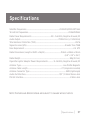
1
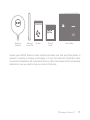
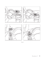
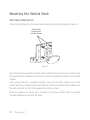
User Guide
Stratus 5
Satellite Radio
Here’s your new
SIRIUS® Stratus 5
Plug & Play Radio
Your new SIRIUS Stratus 5 Plug & Play Radio comes with everything you need to enjoy
SIRIUS® in your car. With available SIRIUS Universal Docking accessories you can use
your Stratus 5 just about anywhere.
Your new Stratus 5 gives you powerful features:
>> Easy-to-read 3-line display.
>> Built-in wireless FM transmitter so you can listen to SIRIUS through your car’s FM
stereo. An FM Presets button makes transmitter frequency changes quick and easy.
>> Jump button that lets you jump to and from your local traffic and weather report
channel with the touch of just one button
Use this manual to familiarize yourself with all of your SIRIUS Stratus 5’s features and
capabilities. For the latest information about your Stratus 5 and other SIRIUS products
and accessories, visit http://www.siriuscanada.ca.
Table of Contents
Table of Contents
4
Warning & Safety Information
6
Canadian Compliance
General Precautions
Warnings
Copyrights & Trademarks
6
7
8
9
Package Contents
10
Installation
12
Location
Mounting the Vehicle Dock
Installing the Magnetic Antenna
Connecting the Cigarette Lighter Adapter
Docking Your SIRIUS Radio
Cable Separation and Routing
Connecting Your Stratus 5 to Your Vehicle’s Audio System
Subscribing to the SIRIUS Service
SIRIUS Stratus 5 Front Panel
Controls
Vehicle Dock Reference Guide
12
14
18
35
35
36
38
44
45
45
47
Operation
48
Display Screen Information
48
[ Table of Contents ]
Changing Channels and Categories
Selecting Channels Directly (Direct Tuning)
Channel Presets
FM Presets/Menu Button
Jump Button
Menu Options
SIRIUS ID
FM Transmitter
Settings
Brightness and Contrast
Signal
Factory Default
Troubleshooting
49
49
50
51
52
53
54
55
57
58
64
64
66
Specifications
67
SIRIUS ID
68
[ Table of Contents ]
Warning & Safety Information
Warning
Changes or modifications not expressly approved by the manufacturer
could void the user’s authority to operate the equipment.
Canadian Compliance
This Class B digital apparatus complies with Canadian ICES-003.
IC STATEMENT
Operation is subject to the following two conditions: (1) this device may not cause interference, and (2) this device must accept any interference, including interference that
may cause undesired operation of the device. For product available in the Canada market, only channel 1~11 can be operated. Selection of other channels is not possible. This
device and its antenna(s) must not be co-located or operation in conjunction with any
other antenna or transmitter. To reduce potential radio interference to other users, the
antenna type and its gain should be so chosen that the equivalent isotropically radiated
power (e.i.r.p) is not more than that permitted for successful communication. IC Radiation Exposure Statement: This equipment complies with IC RSS-102 radiation exposure
limits set forth for an uncontrolled environment. This equipment should be installed and
operated with minimum distance 20cm between the radiator & your body.
[ Warning and Safety Information ]
General Precautions
Liquid Crystal Precautions
If the LCD screen on the radio is damaged, do not to touch the liquid crystal fluid. If any
of the following situations happen, take the action indicated:
1.
If the liquid crystal fluid comes in contact with your skin, wipe the skin area with a
cloth and then wash the skin thoroughly with soap and running water.
2. If the liquid crystal fluid gets into your eye, flush the eye with clean water for at
least 15 minutes. Seek medical care.
3. If the liquid crystal fluid is ingested, flush your mouth thoroughly with water. Drink
large quantities of water and induce vomiting. Seek medical care.
Safety Precautions
Be sure to observe the following warnings. Failure to follow these safety instructions and warnings may result in a serious accident.
• Do not operate your Stratus 5 in a way that might divert your attention from driving
safely. As a driver, you alone are responsible for safely operating your vehicle in
accordance with traffic safety laws at all times.
• Do not install the unit where it may obstruct your view through the windshield, or of
your vehicle’s indicator displays.
• Do not install the unit where it may hinder the function of safety devices such as an
airbag. Doing so may prevent the airbag from functioning properly in the event of
an accident.
• Be sure the unit is installed as described in the installation instructions which
accompany each accessory kit. SIRIUS Satellite Radio is not responsible for issues
arising from installations which were not installed according to the instructions.
• To avoid short circuits, do not open the unit, and never put or leave any metallic
objects (coins, tools, etc.) inside the unit.
• If the unit emits smoke or unusual odors, turn the power off immediately, and
[ Warning and Safety Information ]
disconnect the unit from any power source.
• Do not drop the unit or subject it to strong shocks.
• If the unit doesn’t seem to be working properly, turn the unit off, wait 10 seconds and
then turn it on again.
• The installation and use suggestions contained in this manual are subject to any
restrictions or limitations that may be imposed by applicable law. The purchaser
should check applicable law for any restrictions or limitations before installing
and/or operating this unit.
Warnings
Operating Temperature
The Stratus 5 is designed to operate between -20° to +85° C (-4° to +185° F). Avoid
leaving the radio in a vehicle or elsewhere where the temperature may fall outside this
range. Extreme temperatures or extreme temperature fluctuations can degrade the performance of the LCD display screen, and possibly damage it.
Cleaning and Maintenance
If the radio or accessories become dirty, turn the power off and wipe it clean with a
soft cloth. Do not use hard cloths, strong cleaning fluids, paint thinner, alcohol, or other
volatile solvents to clean. These may cause damage to the radio.
Cigarette Lighter Adapter
The Vehicle Dock cannot be powered directly from a vehicle’s 12VDC power system.
It must be powered from the vehicle’s cigarette lighter or similar power port using the
included Cigarette Lighter Adapter or an equivalent DC power adapter (see your local
electronics dealer). Connecting the Vehicle Dock directly to the vehicle’s 12VDC power
system may result in damage to the Vehicle Dock or SIRIUS radio, or both.
[ Warning and Safety Information ]
Copyrights & Trademarks
© 2008 SIRIUS Satellite Radio Inc. All Rights Reserved.
® “SIRIUS”, the SIRIUS dog logo, channel names and logos are trademarks of SIRIUS
Satellite Radio Inc. All other trademarks, service marks, sports team names, album art,
and logos are the property of their respective owners. All Rights Reserved.
Portions of the software on this radio are licensed under the eCos License. Distribution of eCos requires that the eCos source code be made available to Sirius Satellite
Radio customers. The eCos License and eCos source code are available to the public at
http://www.sirius.com/ecoslicense.
Sirius Satellite Radio reserves all rights to all radio software not covered under the
eCos license. This includes all portions of radio software that were not distributed to
Sirius as part of the eCos operating system.
Hardware, subscription and activation fee required. For full Terms & Conditions, visit
http://siriuscanada.ca. Prices and programming are subject to change. Not available
in HI and AK. Equipment and subscription sold separately. Installation required with
some equipment.
[ Copyrights & Trademarks ]
Package Contents
The following items are included with your purchase of the SIRIUS Stratus 5 radio:
Stratus 5 Radio
Adhesive Dash Mount
10
[ Package Contents ]
Vehicle Dock
Vent Mount &
Extended Vent Hooks
Cigarette Lighter
Adapter
Magnetic
Antenna
Antenna
Cover/Tail
Screws
Alcohol
Swab
User Guide
Unpack your SIRIUS Stratus 5 radio carefully and make sure that everything shown is
present. If anything is missing or damaged, or if your the radio fails to operate, notify
your dealer immediately. We recommend that you retain the original carton and packing
materials in case you need to ship your radio in the future.
[ Package Contents ]
11
Installation
SIRIUS suggests that you have your Stratus 5 professionally installed in your vehicle.
Professional installation provides an experienced technician to install this product in
your vehicle, advice for selecting a suitable mounting location for the Vehicle Dock,
installation of the antenna, and proper routing of all the necessary wires and cables.
If the locations of your SIRIUS radio and your vehicle’s FM antenna make the performance
the SIRIUS radio’s built in FM transmitter within your vehicle poor, a professional
installer will have the necessary accessories to install an optional FM Direct Adapter or
audio cable to connect the audio output of the Vehicle Dock directly to your vehicle’s
audio system. Ask your SIRIUS retailer if they provide professional installation services
or can recommend a professional installation service.
Location
When installing the Vehicle Dock in your vehicle, choose a location in your vehicle where
it will not block your vision, interfere with the vehicle controls, or obstruct the air bag.
The location should be easily accessible and provide good visibility of the display, and
should not be located where it will be in direct sunlight which will affect the visibility of
the display screen.
Figure 1 shows two examples of the Stratus 5 mounted in a vehicle: A is the dash mount
method, and B is the vent mount method using the vent mount clip.
12
[ Installation ]
B.
A.
A.
B.
Figure 1
[ Installation ]
13
Mounting the Vehicle Dock
Dash Mount Method (A)
Attach the dash mount to the vehicle dock using the provided screws (see Figure 2).
Attach Dock
to Mount with
Included Screws
Figure 2
Select the mounting position carefully before adhering the mount to your vehicle. Once
the mount has been adhered to a surface, it will not be possible to remove it and adhere
it again.
Once you’ve selected a mounting location, clean the mounting surface area in the
vehicle with the provided alcohol swab. Peel the protective material off the adhesive on
the foot and press the foot firmly against the vehicle surface.
Allow the adhesive to adhere for a minimum of 2-4 hours before using the mount.
The best adhesion occurs after 24 hours.
14
[ Installation ]
Vent Mount Method (B)
To mount the vehicle dock using the vent mount, install the vent mount as follows:
1.
If the vent louvers in your vehicle are recessed, you may need to use the supplied
longer vent hooks with the vent mount. Refer to Figure 3 and install the longer
vent hooks into the vent mount. Be sure to observe the orientation of the vent
hooks as shown.
Remove
End Cap
Slide Short
Vent Hooks Out
Slide Extended
Vent Hooks In
Replace
End Cap
Figure 3
2. Attach the vent mount to the vehicle dock using the provided screws (see
Figure 4).
Attach Dock
to Mount with
Included Screws
Figure 4
[ Installation ]
15
3. Refer to Figure 5 and attach the vent mount to a heating/air conditioning vent in
your vehicle. Position the two tension springs A against a vent louver B. Then push
the vent mount into the vent, far enough so that the hooks C drop down and hook
the rear of the vent louver (see Figure 6). Once you are sure that the hooks have
grasped a vent louver, the tension springs A will keep the vent mount hooked to
the louver.
A
B
PUSH
C
FM OUT
ANT
D
Figure 5
FM OUT
HOOKED
ANT
Figure 6
16
[ Installation ]
4. The angle of the docking station may be changed by changing the position of foot
D on the vent mount to a different adjustment hole (see Figure 7).
FM OU
T
ANT
ADJUSTMENT
HOLES
D
Figure 7
[ Installation ]
17
Installing the Magnetic Antenna
Caution
Because adhesive is used in the installation of the Rubber Antenna Cover/Tail, we
recommend that you install the antenna at or above room temperature (68° F).
The adhesive on the Rubber Cover/Tail may not adhere properly to the vehicle roof at
temperatures lower than this. Warmer temperatures will also make it easier to route of
the antenna cable through the rubber molding around the windows and in other areas
in the vehicle. Maximum adhesion usually occurs within 72 hours at room temperature,
so you should avoid car washes as well as other contact with the antenna and Rubber
Cover/Tail during this 72 hour period.
Warning
Be sure not to cut, damage, or puncture the external jacket of the antenna
cable during the installation procedure. Damage to the antenna cable can
degrade the SIRIUS signal or make it unavailable, and can also cause water to intrude
via the cable into the antenna causing the antenna to fail.
Do not lengthen or shorten the antenna cable by cutting it. Doing so will cause the
antenna to not function properly.
Installation
Installing the magnetic antenna consists of two steps:
• Mounting the magnetic antenna and Rubber Antenna Cover/Tail on the vehicle
• Routing the antenna cable through the vehicle to the Vehicle Dock
18
[ Installation ]
Antenna Mounting
The SIRIUS Magnetic Mount Vehicle Antenna has a strong magnetic mount designed
to hold it in place during normal driving conditions (highway/city). This also makes the
antenna easy to remove for transferring it to other vehicles.
Figure 8 shows the optimal mounting location for the antenna on several types of
vehicles. These mounting positions should be observed when installing the antenna:
Sedan/Coupe
Pickup Truck
SUV/Mini-Van
Convertible
Figure 8
• Sedan/Coupe/SUV/Mini-Van: Install the antenna at the rear center of the roof, near
the rear window.
• Pickup Truck: Install the antenna at the front center of the roof, near the windshield.
• Convertible: Install the antenna at the front center of the trunk lid, near the rear
window.
[ Installation ]
19
The SIRIUS antenna needs to have an unobstructed area of 3 inches by 3 inches
around it. It is important to mount the antenna where no obstructions will block the
antenna from receiving the SIRIUS signal. Objects which can obstruct the antenna could
be a roof rack, a sunroof, a roof-mounted cargo container, another antenna, etc. If your
vehicle has a potential obstruction, be sure that the SIRIUS antenna is mounted at least
3 inches away from it (but no closer than 3 inches from the roof edge, or trunk lid in the
case of a convertible).
Note: Read
the
Do
and
Do Not
installation tips beginning on page
30
for
additional antenna installation information.
Follow this procedure to mount the antenna:
1.
Select an appropriate mounting position for your type of vehicle that has an
unobstructed area of 3 inches by 3 inches around the antenna.
2. Attach the Rubber Cover/Tail to the antenna, as shown in Figure 9, and press
the antenna cable into the rubber cover/tail. The Rubber Cover/Tail will help to
position the antenna the correct distance from the edge of the roof or trunk lid.
Protective
Strips
Strain
Relief
Rubber Antenna
Cover/Tail
Cable
Magnetic Antenna
(Upside-Down)
Figure 9
3. Clean the surface area of the vehicle where you will be installing the antenna with
the alcohol prep pad.
20
[ Installation ]
4. Peel the protective material from the adhesive strips (see Figure 9) and press the
Rubber Cover/Tail firmly into place on the vehicle.
5. Double check that the location of the antenna and Rubber Cover/Tail are correct, and
continue to press firmly down on the Rubber Cover/Tail for another 30 seconds.
At room temperature (68° F), maximum adhesion usually occurs within 72 hours.
During this period, avoid car washes and other contact with the antenna and the
Rubber Cover/Tail.
Cable Routing
After you have mounted the antenna you can route the antenna cable to the SIRIUS
Vehicle Dock. Separate antenna cable routing procedures are provided for each type of
vehicle: Sedan/Coupe, Pickup Truck, SUV/Mini-Van and Convertible.
Note that additional breakout illustrations for each step of the antenna cable routing
procedures can be found on the SIRIUS website at http://www.siriuscanada.ca. Click
on the Install/Activate link and then follow the link for the Car Installation Tips.
[ Installation ]
21
Sedan/Coupe Antenna Cable Routing Procedure
Figure 10 shows how the antenna cable should be routed from the antenna to your
SIRIUS radio in a sedan/coupe.
2. Route Cable Out of
Window Molding and
Into Weatherstripping
Around Trunk Opening
1. Feed Cable Under
Rubber Molding
Around Window
6. Bring Cable Out To
SIRIUS Receiver
Location
ANTENNA
5. Bring Cable out from
Trim and Route Under
Carpet to Dashboard
or Console.
3. Route Cable
Along Trunk Wall
and Into Cabin
4. Route Cable from Trunk Under
Interior Trim, into Cabin and
Towards Front of Vehicle
Figure 10
22
[ Installation ]
Follow these detailed cable installation instructions:
1.
2.
3.
4.
5.
6.
Feed the cable from the antenna underneath the rubber molding around the rear
window. Use a plastic putty knife or similar object to lift the rubber molding around
the rear window and tuck the antenna cable underneath the molding. Route the
antenna cable around and down the window to the lowest point. If your rear window
does not have rubber molding, SIRIUS recommends consulting with a professional
installer.
Route the antenna cable out of the window molding and into the rubber weather
stripping around the trunk opening. Lift the weather stripping from the opening
and tuck the cable inside it, then replace the weather stripping. To avoid sharp
bends in the cable, run the cable inside of the weather stripping for a few inches,
then remove the cable from the weather stripping inside of the trunk. Keep the
cable away from hinges, gears, etc., that could damage it.
Route the cable out from the rubber weather stripping and along the trunk wall.
Continue routing the cable into the cabin through a conduit or along an existing
wiring harness.
Route the cable through the main cabin area under the interior trim, towards the front
of the vehicle. Use the plastic putty knife to lift the plastic trim just enough to tuck the
cable under underneath. Avoid side airbag locations on back pillars and above the
doors. (Airbag locations are marked with “SRS” logos.) Be careful not to crimp or
cut the cable.
Bring the cable out from the trim near the firewall and route it under the carpet
toward the dashboard or console. Coil any excess cable in a hidden location, such
as under the carpet, keeping it away from any vehicle pedals or controls. Secure
the excess cable with wire ties.
Bring the end of the cable out at the SIRIUS Vehicle Dock location. Leave yourself
enough cable so you can easily connect it to the antenna connector on the Vehicle
Dock.
[ Installation ]
23
Pickup Truck Antenna Cable Routing Procedure
Figure 11 shows how the antenna cable should be routed from the antenna to your SIRIUS
radio in a pickup truck.
ANTENNA
1. Route Cable Under
Rubber Molding
Around Windshield
2. Continue Tucking Cable
Under Molding To
Bottom of Windshield
5. Bring Cable Out to
SIRIUS Receiver
Location
4. Bring Cable out from
Weatherstripping and
Route Under Carpet
Figure 11
24
[ Installation ]
3. Route Cable Out of Molding
and Into Weatherstripping
Around Door Opening.
Continue to Bottom of
Door Opening.
Follow these detailed cable installation instructions:
1.
2.
3.
4.
5.
Use a plastic putty knife or similar tool to lift the rubber molding around the
windshield and tuck the antenna cable underneath it.
Continue tucking the cable underneath the windshield molding around the
windshield to the lowest corner.
At the lowest corner of the windshield, route the cable out of the windshield
molding and into the rubber weather stripping around the door opening. Lift the
weather stripping from the opening and tuck the cable inside it, then replace the
weather stripping. Run the cable inside of the weather stripping to the bottom of
the door opening.
Pull the cable out of the weather stripping at the bottom of the door opening and
route it under the carpet toward the dashboard. Coil any excess cable in a hidden
location, such as under the carpet, keeping it away from any vehicle pedals or
controls. Secure the excess cable with wire ties.
Bring the end of the cable out at the SIRIUS Vehicle Dock location. Leave yourself
enough cable so you can easily connect it to the antenna connector on the Vehicle
Dock.
[ Installation ]
25
SUV/Mini-Van Antenna Cable Routing Procedure
Figure 12 shows how the antenna cable should be routed from the antenna to your
SIRIUS radio in an SUV or a Mini-Van.
1. Feed Cable Under
Rubber Seal Around
Hatch Opening
4. Bring Cable Out To
SIRIUS Receiver
Location
ANTENNA
3. Route Cable
Under Carpet
to Dashboard
2. Route Cable Under Interior
Trim, into Cabin and
Towards Front of Vehicle
Figure 12
26
[ Installation ]
Follow these detailed cable installation instructions:
1.
Feed the antenna cable underneath the rubber weather stripping of the rear
tailgate window/door and route the cable along the rear hatch. Lift the weather
stripping from the opening and tuck the cable inside it, then replace the weather
stripping. Pull the cable out from weather stripping and route it into the cabin
under the interior trim. Avoid hinges or gears that could crimp or cut the cable.
2. Route the cable through the SUV’s main cabin area under the interior trim, towards
the front of the vehicle. Use a plastic putty knife to lift the plastic trim just enough
to tuck the cable under underneath. Avoid side airbag locations on back pillars and
above the doors. (Airbag locations are marked with “SRS” logos.) Be careful not to
crimp or cut the cable.
3. Bring the cable out from the trim near the firewall and route it under the carpet
toward the dashboard or console. Coil any excess cable in a hidden location, such
as under the carpet, keeping it away from any vehicle pedals or controls. Secure
the excess cable with wire ties.
4. Bring the end of the cable out at the SIRIUS Vehicle Dock location. Leave yourself
enough cable so you can easily connect it to the antenna connector on the Vehicle
Dock.
[ Installation ]
27
Convertible Antenna Cable Routing Procedure
Figure 13 shows how the antenna cable should be routed from the antenna to your
SIRIUS radio in a convertible.
6. Bring Cable Out To
SIRIUS Receiver
Location
1. Bring Cable from
Antenna Into Inside
of Trunk Lid
5. Bring Cable out from
Trim and Route Under
Carpet to Dashboard
or Console.
ANTENNA
4. Route Cable from Trunk
Under Interior Trim, into
Cabin and Towards Front
of Vehicle
2. Tape Cable Along
Inside of Lid to
Hinge Strut
3. Tie Cable to Hinge Strut, Allowing
Slack for Lid to Open and Close.
Route Cable Into Cabin
Through Existing Wire
Channel.
Figure 13
28
[ Installation ]
Follow these detailed cable installation instructions:
1.
2.
3.
4.
5.
6.
Bring the cable from the antenna into the trunk at the front edge of the trunk lid.
Keep any bends in the cable loose.
Tape or tie the cable along the inside of the trunk lid to the trunk lid hinge strut.
Allow enough slack in the cable so the trunk lid can easily open and close and keep
the cable away from hinges, gears, etc., that could crimp or cut it.
Route the cable along the trunk wall and into the cabin through a conduit or along
an existing wiring harness.
Route the cable through the main cabin area under the interior trim, towards the
front of the vehicle. Use a plastic putty knife to lift the plastic trim just enough to
tuck the cable under underneath. Avoid side airbag locations on back pillars and
above the doors. (Airbag locations are marked with “SRS” logos.) Be careful not to
crimp or cut the cable.
Bring the cable out from the trim near the firewall and route it under the carpet
toward the dashboard or console. Coil any excess cable in a hidden location, such
as under the carpet, keeping it away from any vehicle pedals or controls. Secure
the excess cable with wire ties.
Bring the end of the cable out at the SIRIUS Vehicle Dock location. Leave yourself
enough cable so you can easily connect it to the antenna connector on the Vehicle
Dock.
[ Installation ]
29
Tips
The following Do and Do Not antenna mounting tips illustrate how to install the antenna
for optimal performance, and also illustrate where the antenna should not be installed.
DO
Mount the antenna
on the roof, at least
3 inches from the
edge.
DO
Mount the antenna
on the roof where
it has a clear view
of the sky in all
directions.
30
[ Installation ]
DO
Mount the antenna
on the roof where
it has at least 3
inches of clear space
around it.
DO
Use the supplied
Rubber Tail Cover to
protect the antenna
cable.
3”
[ Installation ]
31
Do
Not
Don’t mount the
antenna inside the
vehicle, for example,
on the dashboard.
Do
Not
Don’t mount the
antenna on any of
the vehicle’s front,
back or side pillars.
32
[ Installation ]
Do
Not
Don’t mount the antenna close to a roof
rack. Adjust the rack
so it’s further away
from the antenna or
move the antenna
closer to the center
of the roof.
Do
Not
Don’t mount the
antenna close to
another antenna.
Mount it at least 3
inches away.
[ Installation ]
33
Do
Not
Don’t mount the
antenna closer than
3 inches from the
edge of the roof. Use
the supplied rubber
tail/cover as a guide
for judging proper
length and correct
positioning.
After you’ve routed the cable to the SIRIUS Vehicle Dock, connect the antenna cable to
the Ant connection on the right side of the Vehicle Dock. (See Figure 14.)
Antenna
Connection
FM OUT
ANT
Vehicle Dock
(Right Side)
Figure 14
34
[ Installation ]
Antenna
Cable
Connector
Connecting the Cigarette Lighter Adapter
Connect the provided cigarette lighter adapter to the 5VDC connector on the back of the
Vehicle Dock. (See Figure 15.)
Cigarette Lighter
Adapter
Vehicle
Dock
(Left Side)
Power
Connection
12V
Power
Outlet
PWR
AUDIO
Figure 15
Note: Do
Vehicle Dock directly from your vehicle’s 12VDC power
Cigarette Lighter Adapter. This could damage the
Vehicle Dock, your SIRIUS receiver or both.
not power the
system without using the
Docking Your SIRIUS Radio
To place your Stratus 5 into the
Vehicle Dock, align the radio
against the rear of the Dock so
that the rails on the Dock fit into
the mounting slots in the back
of the radio (see Figure 16). Slide
the radio all the way down onto
the Dock so that it fits firmly.
Mounting
Rails
Figure 16
[ Installation ]
35
Cable Separation and Routing
FCC Information
The satellite antenna cable, FM Transmitter Antenna (FMTA) cable and cigarette lighter
adapter (CLA) power cable must be appropriately separated and routed for your radio to
be compliant with federal regulations.
Step 1
The connections on your vehicle dock are
clearly marked. Install your vehicle dock
and connect the antenna cable into the
connection labeled “ANT”, the CLA power
cable into the power connection marked
“PWR” (or 5VDC) and the FMTA cable
into the connection marked “FM OUT”.
(See Figure 17.)
Step 2
LEFT
RIGHT
Power
PWR
FMTA
Antenna
AUDIO
Figure 17
It is important that you keep the three cables as separate from each other as
possible and that you keep the two antenna cables away from the vehicle dock and
from the CLA power cable. The cables must not be bundled together as they exit the
dock (see Figure 18, on page 37).
As a guide, you can follow the diagram in Figure 18, adapting the example to suit your
own vehicle’s configuration. For example, if you cigarette lighter socket is to the left
of the vehicle dock, route the two antenna cables towards the passenger side of the
vehicle. If your cigarette lighter socket is on the right-hand side of the vehicle dock,
route the two antenna cables towards the driver’s door. The CLA cable and antenna
cables MUST be routed in opposite directions. Safely conceal all antenna cables within
door, carpet or cash panels to prevent snags and interference.
36
[ Installation ]
Step 3
Coil any excess cable between the cigarette lighter socket and vehicle dock, keeping it
away from vehicle pedals or controls to prevent any slack which might interfere with the
safe operation of your vehicle. Secure the excess cable with wire ties. If possible, tuck
the coiled part in a hidden location, such as in between the carpet and plastic panel of
the front console (see Figure 19).
Antenna
Cable
SEL
menu
I
2
3
4
5
6
7
8
9
0
FMTA
Cable
Power
Cable
Hide
Excess
Cable
Power
Cable
Figure 18
Step 4
Follow the instructions in this manual
to install, route and hide the antenna
cable and the FMTA cable. Be sure to
coil and secure any excess cable in
a hidden location, such as under the
carpet on the passenger side, keeping it away from vehicle pedals and
controls. The bundled cables should
be as far away from the CLA power
cable as possible (see Figure 20).
Figure 19
D. Route Cable Under Carpet or Console
to vehicle dock or SIRIUS radio
C. Coil Excess Cable Under Carpet
or Mat
B. Pull Carpet or Mat Back
A. Bring Antenna Cable
out from Trim
Figure 20
[ Installation ]
37
Connecting Your Stratus 5 to Your Vehicle’s Audio System
There are two ways to connect your SIRIUS Stratus 5 to your vehicle’s audio system:
Direct Connection or Wireless Connection. Which one will perform best in your vehicle
depends on your vehicle’s audio system.
For the latest information go to http://www.siriuscanada.ca/en/install/vehicle.aspx.
Direct Wired Audio Connection
If your vehicle’s audio system has an “Aux In” or “Line In” jack it is the best quality audio
connection you can use for your SIRIUS radio. (And if the Aux In or Line In connector is
located somewhere on the front of your vehicle radio or elsewhere in the cabin, this is
also the easiest way to connect your SIRIUS receiver.)
1. Purchase an audio cable that matches the connection type of your vehicle’s audio
system and your SIRIUS Vehicle Dock at your local electronics retailer.
• The Vehicle Dock requires a male 1/8” stereo connector.
2. Plug the cable’s male 1/8” stereo connector into the Audio jack on the left side of the
Vehicle Dock. Plug the other end into the Aux In/Line In connector on your vehicle’s
audio system. (See Figure 21.)
Vehicle Dock
(Left Side)
Vehicle Radio
AUDIO
Jack
To AUX IN
or LINE IN
Connector
PWR
AUDIO
Stereo Cable (Sold Separately)
Figure 21
38
[ Installation ]
Direct FM Audio Connection
If your vehicle’s audio system does not have an Aux In/Line In connection, a SIRIUS
FM Direct Adapter (sold separately) will provide the next best quality connection
between your Stratus 5 and your vehicle radio. You will listen to your Stratus 5 through
your car radio’s FM tuner, but the SIRIUS FM Direct Adapter connects your vehicle’s
FM radio directly to the Vehicle Dock’s FM Out jack, eliminating the outside static
and interference you sometimes experience when using a wireless FM connection.
(See Figure 22.)
Vehicle
Antenna
Vehicle Radio
FM Direct Adapter
(Sold Separately)
Antenna
Connection
Vehicle Dock
(Right Side)
FM OUT
Jack
FM OUT
ANT
Figure 22
NOTE: Professional installation may be required. See your local SIRIUS retailer.
The SIRIUS FM Direct Adapter is available at your local SIRIUS retailer or at
http://shop.siriuscanada.ca. Follow the instructions included with the FM
Direct Adapter.
[ Installation ]
39
Cassette Adapter
If your vehicle’s audio system has a cassette player you can purchase a cassette adapter
from your local electronics retailer or from SIRIUS at http://shop.siriuscanada.ca.
Plug the adapter’s connector into the Audio jack on the left side of the Vehicle Dock, and
insert the adapter into your vehicle’s cassette player. (See Figure 23.)
Cassette Adapter (Sold Separately)
Vehicle Dock
(Left Side)
Vehicle Radio
AUDIO
Jack
PWR
AUDIO
Figure 23
Note: Refer to the cassette adapter’s instructions for correct use.
40
[ Installation ]
Wireless Audio Connection
If you cannot connect your SIRIUS Stratus 5 directly to your vehicle’s audio system,
your SIRIUS Stratus 5 contains an FM transmitter that will ‘broadcast’ its audio to your
vehicle’s FM radio.
To use this you need to tune the Stratus 5’s FM transmitter to an FM frequency that’s not
being used in your area (See Figure 24). If you use an FM channel that is being used by a
local broadcaster, it will interfere with the performance of your SIRIUS radio.
Vehicle
FM Antenna
Vehicle Radio
SIRIUS Stratus 5
Match Channels
Figure 24
1.
Tune through your vehicle radio’s FM channels to find an FM channel (between
88.1MHz and 107.9MHz) that is not broadcasting in your area.
• If you’re not sure which FM channels are not broadcasting in your home or travel
cities, you can also go to http://www.siriuscanada.ca/fmchannel and search
for a suggested FM channel based on your zip code.
2.Once you have located an FM channel that is not broadcasting in your area, save it
as a preset on your vehicle radio. This will become your SIRIUS preset.
3.Dock your Stratus 5 and turn its power ON. Wait for the Channel Update to finish
before pressing any buttons.
[ Installation ]
41
4. Press and hold the FM Presets/Menu button (see Figure 25, left). The Menu
Options screen will appear. Press the Channel UP/DOWN buttons to highlight FM
Transmitter and press the Select button to select it.
SEL
menu
I
2
3
4
5
6
FM Presets/
MENU Button
7
8
9
Select
Button
Channel
UP/DOWN
Buttons
0
Figure 25
5. The FM Transmitter screen will appear (see Figure 25, right). Press the Channel
UP/DOWN buttons to highlight FM Presets and press the Select button to select it.
6. T
he FM Presets screen will appear (see Figure 26, left). FM1 will be highlighted. (FM1
is factory-set to 88.1MHz. This may not be the best frequency for your area.)
Figure 26
7. P
ress the Select button to select FM1. The FM Frequency screen will appear (see
Figure 26, right).
8. Use the Channel UP/DOWN buttons to highlight the FM frequency that matches the
channel that you preset on your vehicle radio in Step 2 on page 41, then press the
Select button to select it. (See Figure 27.)
Figure 27
42
[ Installation ]
To listen to SIRIUS, turn your SIRIUS Stratus 5 ON, then turn your vehicle’s FM radio ON
and press the SIRIUS preset you set in Step 2, on page 41. You should hear your SIRIUS
Stratus 5 through your vehicle’s FM radio.
Tip
Tip: If you regularly travel between cities with different active FM channels,
you may need to find channels that are not broadcasting in each city. Your
SIRIUS Stratus 5 can store 5 different preset FM transmitter channels so you
can easily switch to the best FM channel for each city.
Installing the FM Transmitter Antenna
Note: You will only need to install the FM Transmitter Antenna (FMTA) if you are using
the wireless connection option. The use of the FMTA is highly recommended to improve
your audio quality.
The FMTA brings the FM signal transmitted by your SIRIUS radio closer to your vehicle’s
FM antenna to provide a strong FM signal for good reception. To install the FTMA:
1. Connect the FMTA to the vehicle dock. Insert the FMTA 2.5 mm plug into the FM
OUT connector of the vehicle dock. (See Figure 28, left.)
2. Position FMTA inside the vehicle. The FMTA wire should be run with the power
adaptor wire, and placed on the dash board or even placed under the dash pad (if
possible). (See Figure 28, right.) If your Stiletto is mounted to the center console,
the FTMA wire should be run along console.
3. Hide the wires. Depending on the position of your Stiletto, hide the wires by tucking
them into the seams in the dash board or the console seams where possible.
“FM OUT” JACK
2.5 MM PLUG
Figure 28
[ Installation ]
43
Subscribing to the SIRIUS Service
Before you can listen to the SIRIUS service, you need to subscribe to the SIRIUS
Satellite Radio service. To subscribe, do the following:
1.
Be sure that your SIRIUS Stratus 5 is correctly installed, is properly docked in the
Vehicle Dock, and that the antenna is oriented to receive the SIRIUS signal.
2. Turn on the Stratus 5. After the startup sequence,
it will update the SIRIUS channel line-up (see
Figure 29, top). Wait until the channel updates
have completed before pressing any buttons.
3. Once the channels have been updated, the radio
will automatically tune to channel 184 and the
display will change to Call 1-888-539-SIRIUS to
Subscribe (see Figure 29, second from top). You
will not be able to listen to any other channels
until you activate your SIRIUS subscription.
4. Use the Channel up/down buttons to tune to
channel 0 to display your Stratus 5’s unique
12-digit SIRIUS ID Number (SID). See Figure 29,
third from top. Write the SID number down.
• The SID number is also available on your
Stratus 5’s packaging, and may also be
accessed by pressing the FM Presets/Menu
Figure 29
button and selecting Sirius ID.
5. Have your credit card handy and contact SIRIUS on the Internet at:
https://home.siriuscanada.ca/ and follow the prompts to activate your subscription. You can also call SIRIUS toll-free at: 1-888-539-SIRIUS (1-888-539-7474).
6. When you have successfully subscribed to the SIRIUS service your Stratus 5 will
display an alert message (see Figure 29, bottom). To continue, press any button.
You are now ready to begin enjoying SIRIUS Satellite Radio’s digital entertainment, and
can tune to other channels!
44
[ Installation ]
Controls
SIRIUS Stratus 5 Front Panel
Figure 30 and the section following identify and describe the SIRIUS Stratus 5’s
buttons and controls.
1
2
7
SEL
menu
3
4
8
7
I
2
3
4
5
6
5
7
8
9
0
6
Figure 30
[ Controls ]
45
1. Power Button: Turns the Stratus 5’s power On and Off.
2. FM Presets/Menu Button: Selects between different preset frequencies used by the
built-in wireless FM transmitter. Press and hold to access Menu Options to make
setup and feature changes.
3. Jump Button: Jumps to a pre-selected channel.
4. Preset/Direct Tune Buttons (0 – 9): Sets and selects preset channels. Also lets you
directly tune channels by entering the channel number.
5. Category < > Buttons: Navigates through the Category List screen which displays
SIRIUS channel categories.
6. LCD Display: Displays information about the Stratus 5’s operation and about the
program that is playing.
7. Channel Up/Down Buttons: Navigates through channels and display screens.
8. Select (Sel) Button: Selects items highlighted on the display screen. When at
the Default display screen, a press-and-release will display a prompt to enter a
channel number.
46
[ Controls ]
Vehicle Dock Reference Guide
Figure 31 and the section following identify and describe the Vehicle Dock’s features
and connectors.
PWR
AUDIO
1
2
FM OUT
3
3
4
ANT
5
Figure 31
1.
2.
3.
4.
5.
DC5V Power Connector: Power connection for the supplied cigarette lighter
adapter (see page 37).
Audio Out (Audio) Connector: Audio output for directly connecting to your
vehicle’s audio system (see pages 40 & 42).
Docking Rails: Fit-into slots in the back of the Stratus 5 to secure it while it is docked
(see page 37).
FM Out Connector: FM output for use with the optional FM Direct Adapter
(see page 41).
Antenna (Ant) Connector: Connection for the supplied magnetic antenna
(see page 36).
[ Controls ]
47
Operation
Display Screen Information
Whenever you power your Stratus 5 On, the previously-selected channel will
automatically begin playing, and the Stratus 5’s display screen will show the currentlytuned channel, the song or show being played, the artist name and other information.
This screen is referred to as the Default screen in this manual. Figure 32 identifies the
information displayed when listening to a typical broadcast.
Channel Name
Channel Number
Signal Strength
Artist Name
Song Title
Figure 32
You can choose to have the channel name, category name, or the time displayed
on the Default display screen (see Figure 33). To change the display, press-and-hold the
FM Presets/Menu button, use the Channel UP/DOWN buttons and Select button to highlight and select Settings > Display Options > Mode, and then choose the desired display
option. (See Mode, on page 58.)
Channel Name
Category Name
Figure 33
48
[ Operation ]
Time
Changing Channels and Categories
Pressing the Channel up or down button will cause the Stratus 5 to immediately tune
to the next or previous channel.
Pressing the Category < or > button once will display a list of the channels in the current category, highlighting the currently-tuned channel (see Figure 33). Use the Channel
Up/Down buttons to navigate through the list, and press the Select button to choose
a selected channel. Press the Category < or > buttons to scroll through all the different
categories (see Figure 34).
Figure 34
Selecting Channels Directly (Direct Tuning)
You can directly tune to any channel by entering its channel number. Momentarily press
and release the Select button. At the display prompt (Figure 35), use the Preset/Direct
tune (0 – 9) buttons to enter the channel’s three-digit number.
Figure 35
[ Operation ]
49
Channel Presets
You can store up to 10 of your favorite channels as presets for quick access by pressing
the 0 – 9 buttons.
Storing Channel Presets
To store a favorite channel as a preset, do the following:
1. Tune the Stratus 5 to the channel you want to store as a preset.
2. Press and hold for 1 second the numbered preset button (0 – 9) in which you want
to store the channel. You will hear an audible beep and the display will confirm that
the channel has been stored as a preset (see Figure 36).
Figure 36
Note: If
the preset button already has a channel stored in it, the newly-stored
channel will replace the original preset.
Selecting Presets
To tune to a preset channel, press and release one of the 0 – 9 buttons. If you press a
preset button in which no channel has been saved, the Preset Empty message will be
displayed (see Figure 37).
Figure 37
50
[ Operation ]
FM Presets/Menu Button
If you are using a wireless connection between your Stratus 5 and your vehicle’s
audio system (see page 41), you can easily select between the five different preset FM
transmitter frequencies without having to go through the Menu Options (see page 53).
To quickly access the FM Transmitter menu, press the FM Presets/Menu button.
If the FM Transmitter is set to ON: Each press of the FM Presets/Menu button will
switch to the next preset FM Transmitter frequency (see Figure 38).
Figure 38
If the FM Transmitter is set to OFF: The FM On/Off screen appears (see Figure 39).
Use the Channel UP/DOWN buttons to highlight On, and press the Select button.
Figure 39
After selecting On, the FM Presets screen will appear. Each press of the FM Presets/Menu
button will switch to the next preset FM Transmitter frequency (see Figure 38).
[ Operation ]
51
Jump Button
Your Stratus 5 has a special preset button called the Jump button that lets you quickly
tune to a channel that you want to access frequently, such as a music channel or a
sports channel. Pressing the Jump button ‘jumps’ to the specific channel you have
programmed into the Jump button; pressing the Jump button again ‘jumps’ back to
your original channel.
52
[ Operation ]
Menu Options
Menu Options allows you to set and/or change the various features and settings of
your SIRIUS Stratus 5. Press and hold the FM Presets/Menu button to display the Menu
Options screen (see Figure 40).
Figure 40
Use the Channel UP/DOWN buttons to highlight selections in the menu lists and press
the Select button to select them. To exit a menu, press the FM Presets/Menu button.
If you don’t make a selection within 10 seconds the Stratus 5 will exit the Menu Options
screen and revert to the last active display mode. You can exit any Menu Options screen by
repeatedly pressing the FM Presets/Menu button.
[ Menu Options ]
53
SIRIUS ID
This displays your Stratus 5’s 12-digit SIRIUS ID (SID) number (see Figure 41).
Figure 41
The SID is unique to each SIRIUS radio, and is required to activate your service. We
recommend that you write this number in the space provided near the end of this user guide.
No adjustments are allowed in this mode. To exit, press the FM Presets/Menu button or
the Select button.
54
[ Menu Options ]
FM Transmitter
The FM Transmitter menu option allows you to enable or disable the Stratus 5’s
built-in FM transmitter, and select up to 5 different preset FM transmitter frequencies
(see Figure 42).
Figure 42
FM P resets
You can select from the 5 preset FM transmitter frequencies:
1.
On the FM Transmitter screen (Figure 42), highlight and select FM Presets.
The FM Presets screen will appear (see Figure 43, left).
Figure 43
2. U
se the Channel UP/DOWN buttons to highlight the FM preset you want
(FM1 – FM5), and press the Select button. The FM Frequency screen will appear,
showing the currently-selected frequency for that preset (see Figure 43, right).
3. To select the FM Preset: Press the Select button. To change the FM Preset’s FM
frequency: Use the Channel UP/DOWN buttons to change the FM frequency, then
press the Select button.
To exit, press the FM Presets/Menu button 3 times.
[ Menu Options ]
55
FM On/Off
You can turn the Stratus 5’s FM transmitter ON and OFF:
1.
rom the FM Transmitter screen (see Figure 42, on page 55), highlight and select
F
FM On/Off. The FM On/Off screen will appear (see Figure 44).
Figure 44
2. To turn the FM transmitter ON, highlight and select On; to turn the FM transmitter
OFF, highlight and select Off.
To exit, press the FM Presets/Menu button twice.
56
[ Menu Options ]
Settings
The Settings menu lets you access the Display Options, Audio Level, Tones, Clock, Jump
Settings and Channel Lock menu options (see Figure 45).
Figure 45
Display Options
The Display Options menu (Figure 46) lets you adjust the Stratus 5’s LCD display to
improve its visibility in different lighting conditions, and to display different types of
information.
Figure 46
[ Menu Options ]
57
Brightness and Contrast
Brightness adjusts the overall intensity of the LCD display to help with viewing in different
lighting conditions. Contrast adjusts the relationship between the background and the
text on the LCD display.
Use the Channel UP/DOWN buttons to adjust the brightness and contrast. The bar graphs
will indicate the change (see Figure 47).
Figure 47
Mode
The Mode screen (Figure 48) lets you change the default display screen to display
either the channel name, category name, or the time. See Figure 49 for examples.
Use the Channel Up/Down buttons to select the desired mode and press the Select
button to set your choice.
Figure 48
Channel Name
Category Name
Figure 49
58
[ Menu Options ]
Time
Audio Level
The Audio Level screen lets you use the Channel UP/DOWN buttons to adjust the
Stratus 5’s audio output level (see Figure 50). The bar graph will indicate the change.
Figure 50
Tones
You can select whether to hear an audible confirmation tone as you navigate menus
and lists. To turn the tones on or off, use the Channel Up/Down buttons to select your
choice and press the Select button to set your choice (see Figure 51).
Figure 51
[ Menu Options ]
59
Clock
The Clock screen (see Figure 52) allows you to setup the clock that appears on the
Default screen, based on the format desired and the time zone in which you reside. The
actual time is provided via the SIRIUS satellite signal, and will automatically update
your Stratus 5.
Figure 52
Format
Displays the time in either 12-hour (default) or 24-hour format (see Figure 53).
Figure 53
Time Zone
Since the clock adjusts the time automatically, it is important to specify your time zone.
Select your time zone from the list of the available time zones (see Figure 54).
Figure 54
60
[ Menu Options ]
Daylight Savings Time
Select On if your area observes Daylight Savings Time; select Off if your area does not
(see Figure 55).
Figure 55
[ Menu Options ]
61
Channel Lock
Your SIRIUS Stratus 5 has the ability to lock channels you do not want others (such as
children) to access without your permission. Locked channels will not appear on the
Channel List screen, or when browsing channels with the Channel UP/DOWN buttons.
When the anyone tries to access a locked channel using the Direct Tuning function (see
page 49), an Enter Code screen will be displayed and the channel won’t be accessed until
the correct code is entered.
Locking and Unlocking Channels
1.
Select the Channel Lock menu option. The Channel Lock screen will appear
(see Figure 56, left).
Figure 56
2. Select Lock/Unlock. You will need to enter a lock code to proceed. Refer to Setting
the Lock/Unlock Code, on page 63 for information on how to set the lock code.
3. Once you enter the lock code the Lock/Unlock screen will appear (see
Figure 55, right). Use the Channel UP/DOWN buttons to highlight the channel you
wish to lock or unlock from the channel list. Pressing the Select button will either
add a padlock icon next to the channel name to indicate that the channel will be
locked, or unlock a locked channel by removing the padlock icon.
62
[ Menu Options ]
Setting the Lock/Unlock Code
To set the lock code:
1.
Select the Channel Lock menu option. The Channel Lock screen will appear
(see Figure 56, left, on page 62)
2. Select the Edit Code menu option. The New Code screen will be displayed
(see Figure 57). Enter a four-digit code using the 0 – 9 number buttons. You will
then be prompted to enter the new code again to confirm.
Figure 57
3. When the lock code is confirmed, the lock code is set.
You can use this same procedure to change the lock code after you have set it.
Note: If you have
Service for help.
forgotten your
Channel Lock
code, call
SIRIUS Customer
[ Menu Options ]
63
Signal
When using the optional Home Docking Station or boombox indoors, it is important
to aim the antenna for maximum signal reception. The Signal screen (see Figure 58)
visually shows the strength of the satellite and terrestrial signals being received by the
Stratus 5. (Refer to the Home Docking Station installation guide for more information
about properly orienting the antenna.)
Figure 58
The SAT bar graph indicates the strength of the satellite signal strength; the TER bar
graph indicates the strength of the terrestrial signal strength (if available).
Factory Default
The Factory Default menu option will restore most every feature of the radio to the
original factory settings. The following is a list of all features affected by the Factory
Default option:
•
•
•
•
•
•
64
All Channel Presets are cleared
Radio set to Normal Tuning Mode
Display brightness set to 50%
Display Contrast set to 50%
FM Transmitter set to ON
FM Transmitter Preset #1 set to
88.1 MHz
[ Menu Options ]
• Jump setting is cleared
• Top line display mode set to Channel
Name
• Audio level set to -3dB
• Confirmation Tone set to On
Note that the Parental Control feature is not affected by the Factory Default option. This
prevents someone from circumventing the Channel Lock feature. Channels that have
been locked will remain locked.
To activate the Factory Default feature, and restore the above features to their factory
defaults, do the following:
1.
Highlight and select Factory Default from the Menu Options screen. The
Restore? screen will appear (see Figure 59, left).
Figure 59
2. Highlight and select Yes to restore the above settings to the their factory
default settings, or select No to leave them as-is and return to the Menu Options
screen.
3. If you select Yes, a confirmation screen appears (see Figure 58, right). Use the
Channel UP/DOWN buttons to select Yes to restore all settings to the settings
from the factory, or select No to leave them as-is and return to the Menu Options
menu.
4. If you select Yes, the Stratus 5 will restore the original factory settings (see
Figure 60).
Figure 60
5. When the Restore is complete, the Stratus 5 will tune to the last channel that was
active before the Factory Default was begun.
[ Menu Options ]
65
Troubleshooting
Symptom
Solution
The Stratus 5 does not
power on
Blown fuse, or the power cable is not properly connected.
Display reads:
No Antenna
The satellite antenna is not connected to the radio.
Display reads:
Acquiring Signal
No satellite signal is being received.
• Check for a bad fuse and check power cable connection
• Check the satellite antenna connection to the radio.
• Check for obstacles over or around the satellite antenna.
• Change the vehicle location to eliminate nearby obstacles
(bridges, overpasses, tress, buildings, etc.).
Audio static or loss of
clarity
The FM frequency contains static.
• Locate a quiet FM frequency on your vehicle radio and
set the FM transmitter frequency of the SIRIUS radio to
match.
• If using the Vehicle Dock AUDIO OUT connector, check the
cable connections.
No sound
The audio cables are not connected, or the FM radio is set
to the wrong frequency.
• Check the audio cables at the SIRIUS radio and the vehicle’s audio system.
• Tune the vehicle’s FM radio to the same FM frequency the
SIRIUS FM transmitter is tuned.
66
[ Troubleshooting ]
Specifications
Satellite Frequencies.........................................................................2322.293/2330.207 MHz
Terrestrial Frequencies.........................................................................................2326.250MHz
Radio Power Requirements.......................................... 4.9 – 5.6 Volts, Negative Ground, DC
Audio Output.....................................................................................700mVrms (+/- 50mVrms)
Total Harmonic Distortion (THD)....................................................................................... <0.2%
Signal-to-noise (S/N)..................................................................................... Greater than 73dB
Fuse Requirement.............................................................................................................2A ATC
Radio Dimensions (Length x Width x Depth).................................... 114mm x 48mm x 15mm
(4.5” x 1.9” x 0.6”)
Radio Weight............................................................................................................. 85g (3.0 oz.)
Cigarette Lighter Adapter Power Requirements............. 9 –16 Volts, Negative Ground, DC
Antenna Type............................................................................................. Low Profile Magnetic
Antenna Cable Length........................................................................... 21’ (single micro-cable)
Antenna Connector Type................................................................................ SMB (right-angle)
Audio Out Interface........................................................................... 1/8” / 3.5mm Stereo Jack
FM Out Interface....................................................................................................... 2.5mm Jack
Note: Features and Specifications are subject to change without notice.
[ Specifications ]
67
SIRIUS ID
Write down the SIRIUS ID (SID) of your SIRIUS Stratus 5 in the space provided
below.
SID: ____________________________________
68
[ SIRIUS ID ]
SIRIUS Customer Service: 1-888-539-7474
[email protected]
SIRIUS Canada Inc.
135 Liberty Street, 4th Floor
Toronto, Ontario M6K 1A7
1-888-539-7474
http://
siriuscanada.ca
http: //siriuscanada.ca
SIRIUS Canada Inc.
135 Liberty Street, 4th Floor
Toronto, Ontario M6K 1A7
1-888-539-7474
Stratus 5 User Guide (052708a)