1
Dell OpenManage™ Remote Assistant Card II
USER’S GUIDE
www.dell.com
support.dell.com
Notes, Notices, and Cautions
Throughout this guide, blocks of text may be accompanied by an icon and printed in
bold type or in italic type. These blocks are notes, notices, and cautions, and they are
used as follows:
NOTE: A NOTE indicates important information that helps you make better use of
your computer system.
NOTICE: A NOTICE indicates either potential damage to hardware or loss
of data and tells you how to avoid the problem.
CAUTION: A CAUTION indicates a potentially hazardous situation which, if
not avoided, may result in minor or moderate injury.
____________________
Information in this document is subject to change without notice.
© 2001 Dell Computer Corporation. All rights reserved.
Reproduction in any manner whatsoever without the written permission of Dell Computer
Corporation is strictly forbidden.
Trademarks used in this text: Dell, the DELL logo, PowerEdge, PowerVault, and Dell OpenManage
are trademarks of Dell Computer Corporation; Microsoft, Windows, Windows NT, and MS-DOS
are registered trademarks of Microsoft Corporation; Novell and NetWare are registered trademarks
of Novell, Inc.; Intel is a registered trademark of Intel Corporation.
Other trademarks and trade names may be used in this document to refer to either the entities
claiming the marks and names or their products. Dell Computer Corporation disclaims any proprietary interest in trademarks and trade names other than its own.
November 2001
Rev. A01
Preface
This guide is intended for anyone who uses a Dell OpenManage Remote Assistant
Card II (DRAC II). It can be used by both first-time and experienced system users who
want to learn about the features and operation of the DRAC II. The chapters and
appendixes are summarized as follows:
•
•
•
Chapter 1, “Introduction,” provides an overview of the DRAC II features.
•
Chapter 4, “Maintenance and Troubleshooting,” explains basic troubleshooting
and maintenance of the DRAC II.
•
Appendix A, “Technical Specifications,” contains reference material for users
interested in learning more about the details of the DRAC II.
•
Appendix B, “Racconf Utility,” contains information on configuring the DRAC II
using the racconf utility.
Chapter 2, “Installing the DRAC II,” explains how to install the DRAC II.
Chapter 3, “Configuring and Using the DRAC II,” explains how to configure and
use a DRAC II.
Other Documents You May Need
Besides this User’s Guide, the following documentation is included with your system:
•
Your system’s Installation and Troubleshooting Guide, which provides detailed
information on your system and procedures for removing and replacing parts on
your system
•
Your system’s User’s Guide, which provides general information about your
system
•
•
Your System Information document that came with the system
Your system’s management software documentation
iii
Typographical Conventions
The following list defines (where appropriate) and illustrates typographical
conventions used as visual cues for specific elements of text throughout this
document:
•
Keycaps, the labeling that appears on the keys on a keyboard, are enclosed
in angle brackets.
Example: <Enter>
•
Key combinations are series of keys to be pressed simultaneously (unless
otherwise indicated) to perform a single function.
Example: <Ctrl><Alt><Enter>
•
Commands presented in lowercase bold are for reference purposes only and
are not intended to be typed when referenced.
Example: “Use the format command to . . . .”
In contrast, commands presented in the Courier New font are part of an
instruction and intended to be typed.
Example: “Type format a: to format the diskette in drive A.”
•
Filenames and directory names are presented in lowercase bold.
Examples: autoexec.bat and c:\windows
•
Syntax lines consist of a command and all its possible parameters. Commands
are displayed in lowercase bold; variable parameters (those for which you
substitute a value) are displayed in lowercase italics; constant parameters are
displayed in lowercase bold. The brackets indicate items that are optional.
Example: del [drive:] [path] filename [/p]
•
Command lines consist of a command and may include one or more of the
command’s possible parameters. Command lines are presented in the Courier
New font.
Example: del c:\myfile.doc
•
Screen text is text that appears on the screen of your monitor or display. It can be
a system message, for example, or it can be text that you are instructed to type
as part of a command (referred to as a command line). Screen text is presented
in the Courier New font.
Example: The following message appears on your screen:
No boot device available
Example: “Type md c:\programs and press <Enter>.”
•
Variables are placeholders for which you substitute a value. They are presented in
italics.
Example: DIMM_x (where x represents the DIMM socket designation).
iv
Contents
Chapter 1
Introduction. . . . . . . . . . . . . . . . . . . . . . . . . . . . . . . . . 1-1
DRAC II Kit. . . . . . . . . . . . . . . . . . . . . . . . . . . . . . . . . . . . . . . . . . . . . . . . . . . . . . . .
DRAC II Features. . . . . . . . . . . . . . . . . . . . . . . . . . . . . . . . . . . . . . . . . . . . . . . . . . .
Supported Configurations . . . . . . . . . . . . . . . . . . . . . . . . . . . . . . . . . . . . . . . . . . . .
Hardware Platforms . . . . . . . . . . . . . . . . . . . . . . . . . . . . . . . . . . . . . . . . . . . . .
Operating System Platforms . . . . . . . . . . . . . . . . . . . . . . . . . . . . . . . . . . . . . .
BIOS, ESM, and BMC Requirements. . . . . . . . . . . . . . . . . . . . . . . . . . . . . . . .
Instrumentation Requirements . . . . . . . . . . . . . . . . . . . . . . . . . . . . . . . . . . . . . . . .
Version Compatibility. . . . . . . . . . . . . . . . . . . . . . . . . . . . . . . . . . . . . . . . . . . . . . . .
How the DRAC II Works . . . . . . . . . . . . . . . . . . . . . . . . . . . . . . . . . . . . . . . . . . . . .
DRAC II Software Modules . . . . . . . . . . . . . . . . . . . . . . . . . . . . . . . . . . . . . . .
DRAC II in the Dell OpenManage Environment . . . . . . . . . . . . . . . . . . . . . . . .
When the System is Operational . . . . . . . . . . . . . . . . . . . . . . . . . . . . . . . . . . .
When the System is Nonoperational . . . . . . . . . . . . . . . . . . . . . . . . . . . . . . . .
DRAC II Security . . . . . . . . . . . . . . . . . . . . . . . . . . . . . . . . . . . . . . . . . . . . . . . . . . .
Encrypted Password Authentication . . . . . . . . . . . . . . . . . . . . . . . . . . . . . . . .
Valid Login . . . . . . . . . . . . . . . . . . . . . . . . . . . . . . . . . . . . . . . . . . . . . . . . . . . .
VT100 Connection Capabilities. . . . . . . . . . . . . . . . . . . . . . . . . . . . . . . . . . . . .
DRAC II Web Console . . . . . . . . . . . . . . . . . . . . . . . . . . . . . . . . . . . . . . . . . . .
Chapter 2
1-1
1-1
1-2
1-3
1-3
1-3
1-4
1-5
1-5
1-6
1-7
1-7
1-8
1-8
1-8
1-8
1-9
1-9
Installing the DRAC II . . . . . . . . . . . . . . . . . . . . . . . . . 2-1
System Requirements. . . . . . . . . . . . . . . . . . . . . . . . . . . . . . . . . . . . . . . . . . . . . . .
Upgrading the System BIOS . . . . . . . . . . . . . . . . . . . . . . . . . . . . . . . . . . . . . . . . .
Installing the DRAC II . . . . . . . . . . . . . . . . . . . . . . . . . . . . . . . . . . . . . . . . . . . . . . .
Installing the Software. . . . . . . . . . . . . . . . . . . . . . . . . . . . . . . . . . . . . . . . . . . . . . .
Installing the Managed Node Software Under
Windows NT or Windows 2000 . . . . . . . . . . . . . . . . . . . . . . . . . . . . . . . . . . . .
Express Setup . . . . . . . . . . . . . . . . . . . . . . . . . . . . . . . . . . . . . . . . . . . . . . . . .
Custom Setup . . . . . . . . . . . . . . . . . . . . . . . . . . . . . . . . . . . . . . . . . . . . . . . . .
Installing the Managed Node Software Under
NetWare 5.x and NetWare 6.0 . . . . . . . . . . . . . . . . . . . . . . . . . . . . . . . . . . . . .
2-1
2-1
2-2
2-4
2-5
2-6
2-6
2-8
v
Installing the Managed Node Software Under Red Hat Linux 7.0,
Red Hat Linux 7.1, or Red Hat Linux 7.2 . . . . . . . . . . . . . . . . . . . . . . . . . . . . . 2-9
Kernel Support . . . . . . . . . . . . . . . . . . . . . . . . . . . . . . . . . . . . . . . . . . . . . 2-9
DRAC II Software Basics for Red Hat Linux . . . . . . . . . . . . . . . . . . . . . . 2-11
Open Issues With DRAC II Under Red Hat Linux . . . . . . . . . . . . . . . . . . 2-12
Installing the Management Station Software for Windows NT or
Windows 2000 . . . . . . . . . . . . . . . . . . . . . . . . . . . . . . . . . . . . . . . . . . . . . . . . 2-12
Custom Setup . . . . . . . . . . . . . . . . . . . . . . . . . . . . . . . . . . . . . . . . . . . . . 2-12
Remote Access Service Setup for Windows NT
Management Stations . . . . . . . . . . . . . . . . . . . . . . . . . . . . . . . . . . . . . . . . . . 2-13
Dial-Up Networking Setup for Windows NT Management Stations . . . . . . . 2-14
Remote Access Service Setup for Windows 2000
Management Stations . . . . . . . . . . . . . . . . . . . . . . . . . . . . . . . . . . . . . . . . . . 2-16
Dial-Up Networking Setup for Windows 2000 Management Stations. . . . . . 2-17
Firmware Installation . . . . . . . . . . . . . . . . . . . . . . . . . . . . . . . . . . . . . . . . . . . . . . . 2-17
Chapter 3
Configuring and Using the DRAC II . . . . . . . . . . . . . . 3-1
Configuring the DRAC II in the
Dell OpenManage Environment . . . . . . . . . . . . . . . . . . . . . . . . . . . . . . . . . . . . . . . 3-2
Adding a DRAC II Administrator . . . . . . . . . . . . . . . . . . . . . . . . . . . . . . . . . . . . 3-2
Configuring the Network Properties of the DRAC II . . . . . . . . . . . . . . . . . . . . 3-4
Configuring the Modem Properties of the DRAC II . . . . . . . . . . . . . . . . . . . . . 3-5
Configuring the Alert Properties of the DRAC II. . . . . . . . . . . . . . . . . . . . . . . . 3-6
Configuring Your Network to Access the DRAC II From the Internet . . . . . . . 3-6
Requirements for Management Stations to Access DRAC II
From the Internet . . . . . . . . . . . . . . . . . . . . . . . . . . . . . . . . . . . . . . . . . . . 3-6
Configuring a Desktop, Laptop, or PowerEdge System as
the DRAC II Web Console. . . . . . . . . . . . . . . . . . . . . . . . . . . . . . . . . . . . . 3-8
Configuring the DRAC II Outside the Dell OpenManage Environment . . . . . . . . . . 3-9
Using the Racconf Utility Under Windows NT and Windows 2000 . . . . . . . . 3-9
Using the Racconf Utility Under NetWare . . . . . . . . . . . . . . . . . . . . . . . . . . . 3-10
Using the Racconf Utility Under Red Hat Linux . . . . . . . . . . . . . . . . . . . . . . . 3-13
Using the DRAC II Web Console . . . . . . . . . . . . . . . . . . . . . . . . . . . . . . . . . . 3-14
Connecting to the Serial Port . . . . . . . . . . . . . . . . . . . . . . . . . . . . . . . . . . . . . 3-17
DRAC II Console Redirection With Windows NT and Windows 2000 . . . . . . 3-17
DRAC II Console Redirection With NetWare . . . . . . . . . . . . . . . . . . . . . . . . . 3-18
DRAC II Console Redirection With Red Hat Linux . . . . . . . . . . . . . . . . . . . . 3-18
Connecting to the DRAC II by Modem. . . . . . . . . . . . . . . . . . . . . . . . . . . . . . 3-19
Multiple Sessions in DRAC II Web Console. . . . . . . . . . . . . . . . . . . . . . . . . . 3-20
Missing System Information . . . . . . . . . . . . . . . . . . . . . . . . . . . . . . . . . . . . . 3-20
System Monitoring and Alerting on Windows NT and Windows 2000 . . . . . 3-20
Location of DRAC II Event Logs . . . . . . . . . . . . . . . . . . . . . . . . . . . . . . . 3-21
Paging. . . . . . . . . . . . . . . . . . . . . . . . . . . . . . . . . . . . . . . . . . . . . . . . . . . . . . . 3-22
Alphanumeric Paging . . . . . . . . . . . . . . . . . . . . . . . . . . . . . . . . . . . . . . . 3-22
vi
Test the Pager Feature in IT Assistant . . . . . . . . . . . . . . . . . . . . . . . . . .
Remote Access to the System Utility Partition. . . . . . . . . . . . . . . . . . . .
Using Remote Floppy Boot (RFB) . . . . . . . . . . . . . . . . . . . . . . . . . . . . . . . . .
Platforms Supporting RFB. . . . . . . . . . . . . . . . . . . . . . . . . . . . . . . . . . . .
Starting RFB . . . . . . . . . . . . . . . . . . . . . . . . . . . . . . . . . . . . . . . . . . . . . .
Stopping RFB . . . . . . . . . . . . . . . . . . . . . . . . . . . . . . . . . . . . . . . . . . . . .
Configuring the PowerEdge 8450 for RFB . . . . . . . . . . . . . . . . . . . . . . .
Chapter 4
3-22
3-22
3-23
3-23
3-24
3-24
3-24
Maintenance and Troubleshooting . . . . . . . . . . . . . . 4-1
Replacing the Battery Pack . . . . . . . . . . . . . . . . . . . . . . . . . . . . . . . . . . . . . . . . . . .
Removing the Battery Pack . . . . . . . . . . . . . . . . . . . . . . . . . . . . . . . . . . . . . . .
Installing the New Battery Pack . . . . . . . . . . . . . . . . . . . . . . . . . . . . . . . . . . . .
Common Problem Situations and Solutions . . . . . . . . . . . . . . . . . . . . . . . . . . . . . .
DRAC II Alert Messages . . . . . . . . . . . . . . . . . . . . . . . . . . . . . . . . . . . . . . . . . . . . .
Removing a DRAC II From a System . . . . . . . . . . . . . . . . . . . . . . . . . . . . . . . . . . .
4-1
4-1
4-2
4-2
4-4
4-6
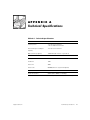
Appendix A
Technical Specifications . . . . . . . . . . . . . . . . . . . . . . . A-1
Appendix B
Racconf Utility . . . . . . . . . . . . . . . . . . . . . . . . . . . . . . . B-5
Command Line Options. . . . . . . . . . . . . . . . . . . . . . . . . . . . . . . . . . . . . . . . . . . . . . B-5
Default Display . . . . . . . . . . . . . . . . . . . . . . . . . . . . . . . . . . . . . . . . . . . . . . . . . . . . B-6
/a (/a–/a15) — Display Administrator Entry . . . . . . . . . . . . . . . . . . . . . . . . . . . . . . . B-7
/b — Display Battery Information . . . . . . . . . . . . . . . . . . . . . . . . . . . . . . . . . . . . . . B-9
/c — Configure Card . . . . . . . . . . . . . . . . . . . . . . . . . . . . . . . . . . . . . . . . . . . . . . . . B-9
/d — Hard Reset . . . . . . . . . . . . . . . . . . . . . . . . . . . . . . . . . . . . . . . . . . . . . . . . . . B-10
/fb — Firmware Upgrade, Boot Block Method (MS-DOS only) . . . . . . . . . . . . . . . B-10
/fi — Firmware Upgrade . . . . . . . . . . . . . . . . . . . . . . . . . . . . . . . . . . . . . . . . . . . . B-11
/h or /? — Help. . . . . . . . . . . . . . . . . . . . . . . . . . . . . . . . . . . . . . . . . . . . . . . . . . . . B-12
/i — Miscellaneous Information. . . . . . . . . . . . . . . . . . . . . . . . . . . . . . . . . . . . . . . B-12
/l — Card Health . . . . . . . . . . . . . . . . . . . . . . . . . . . . . . . . . . . . . . . . . . . . . . . . . . B-13
/m (/m0–/m7) — Display Management Station Entry . . . . . . . . . . . . . . . . . . . . . . B-13
/o — Restore Default Configuration . . . . . . . . . . . . . . . . . . . . . . . . . . . . . . . . . . . B-14
/r — Soft Reset . . . . . . . . . . . . . . . . . . . . . . . . . . . . . . . . . . . . . . . . . . . . . . . . . . . B-15
/s — Card Shutdown . . . . . . . . . . . . . . . . . . . . . . . . . . . . . . . . . . . . . . . . . . . . . . . B-15
/t (/t0–/t7) — Display SNMP Trap Destination Entry . . . . . . . . . . . . . . . . . . . . . . . B-15
/w — Write Configuration File . . . . . . . . . . . . . . . . . . . . . . . . . . . . . . . . . . . . . . . . B-16
Configuration File (racconf.ini) . . . . . . . . . . . . . . . . . . . . . . . . . . . . . . . . . . . . . . . . B-17
AdminEntry. . . . . . . . . . . . . . . . . . . . . . . . . . . . . . . . . . . . . . . . . . . . . . . . . . . B-17
AlertTableConfig. . . . . . . . . . . . . . . . . . . . . . . . . . . . . . . . . . . . . . . . . . . . . . . B-19
AutoRecoveryConfig . . . . . . . . . . . . . . . . . . . . . . . . . . . . . . . . . . . . . . . . . . . B-20
DHCPConfig . . . . . . . . . . . . . . . . . . . . . . . . . . . . . . . . . . . . . . . . . . . . . . . . . . B-21
DialOutConfig . . . . . . . . . . . . . . . . . . . . . . . . . . . . . . . . . . . . . . . . . . . . . . . . . B-21
vii
ESMConfig. . . . . . . . . . . . . . . . . . . . . . . . . . . . . . . . . . . . . . . . . . . . . . . . . . .
ExtModem . . . . . . . . . . . . . . . . . . . . . . . . . . . . . . . . . . . . . . . . . . . . . . . . . . .
ManagementStation . . . . . . . . . . . . . . . . . . . . . . . . . . . . . . . . . . . . . . . . . . .
MiscConfig. . . . . . . . . . . . . . . . . . . . . . . . . . . . . . . . . . . . . . . . . . . . . . . . . . .
NetConfig. . . . . . . . . . . . . . . . . . . . . . . . . . . . . . . . . . . . . . . . . . . . . . . . . . . .
PCCardModem . . . . . . . . . . . . . . . . . . . . . . . . . . . . . . . . . . . . . . . . . . . . . . .
PCIVoltConfig. . . . . . . . . . . . . . . . . . . . . . . . . . . . . . . . . . . . . . . . . . . . . . . . .
PPPConfig . . . . . . . . . . . . . . . . . . . . . . . . . . . . . . . . . . . . . . . . . . . . . . . . . . .
RACTempConfig . . . . . . . . . . . . . . . . . . . . . . . . . . . . . . . . . . . . . . . . . . . . . .
SNMPDest . . . . . . . . . . . . . . . . . . . . . . . . . . . . . . . . . . . . . . . . . . . . . . . . . . .
SnmpServerConfig. . . . . . . . . . . . . . . . . . . . . . . . . . . . . . . . . . . . . . . . . . . . .
TerminalServerConfig . . . . . . . . . . . . . . . . . . . . . . . . . . . . . . . . . . . . . . . . . .
TCPIPConfig. . . . . . . . . . . . . . . . . . . . . . . . . . . . . . . . . . . . . . . . . . . . . . . . . .
WallAdapterVoltConfig. . . . . . . . . . . . . . . . . . . . . . . . . . . . . . . . . . . . . . . . . .
B-21
B-22
B-23
B-23
B-24
B-24
B-25
B-26
B-27
B-28
B-29
B-29
B-29
B-30
Glossary
Index
Figures
Tables
Figure 2-1.
Figure 2-2.
Figure A-1.
DRAC II Connectors . . . . . . . . . . . . . . . . . . . . . . . . . . . . . . . . . . . . . 2-3
DRAC II I/O Connectors. . . . . . . . . . . . . . . . . . . . . . . . . . . . . . . . . . . 2-4
DRAC II Connectors . . . . . . . . . . . . . . . . . . . . . . . . . . . . . . . . . . . . . A-4
Table 1-1.
Table 1-2.
BIOS, ESM, and BMC Requirements . . . . . . . . . . . . . . . . . . . . . . . . 1-3
DRAC II Firmware Level and Matching Managed Node
Software Version . . . . . . . . . . . . . . . . . . . . . . . . . . . . . . . . . . . . . . . . 1-4
Backwards Compatibility . . . . . . . . . . . . . . . . . . . . . . . . . . . . . . . . . . 1-5
Software Modules . . . . . . . . . . . . . . . . . . . . . . . . . . . . . . . . . . . . . . . 1-6
Dell OpenManage Software Modules . . . . . . . . . . . . . . . . . . . . . . . . 1-6
Kernels Supported by DRAC II . . . . . . . . . . . . . . . . . . . . . . . . . . . . . 2-9
Platforms Supporting RFB . . . . . . . . . . . . . . . . . . . . . . . . . . . . . . . . 3-23
DRAC II Alert Messages . . . . . . . . . . . . . . . . . . . . . . . . . . . . . . . . . . 4-4
Technical Specifications . . . . . . . . . . . . . . . . . . . . . . . . . . . . . . . . . . A-1
Table 1-3.
Table 1-4.
Table 1-5.
Table 2-1.
Table 3-1.
Table 4-1.
Table A-1.
viii
CHAPTER 1
Introduction
The Dell OpenManage™ Remote Assistant Card II (DRAC II) is an optional system
management card designed to provide remote management capabilities for Dell™
PowerEdge™ systems. With the addition of the DRAC II, system administrators can
manage and monitor a PowerEdge system through a modem or network connection,
even when the system itself is down.
DRAC II Kit
The DRAC II kit includes:
•
•
•
•
DRAC II hardware
•
•
•
Dell OpenManage Server Assistant CD
DRAC II version 2.4 or later firmware flash diskette
External power adapter and power cable (in countries where certified)
Personal Computer Memory Card International Association (PCMCIA) modem
(optional)
Dell OpenManage Systems Management CD
Documentation CD
DRAC II Features
The DRAC II offers a complete hardware and software solution to the challenge of
remote systems management. A major feature of the DRAC II is the ability to allow an
administrator to remotely access an inoperable system and get the system up and
running as quickly as possible. The DRAC II provides alert notification when the system is down and allows full access to the down system. In addition, the DRAC II logs
the probable cause of the system crash and saves the current error display.
The DRAC II is a peripheral component interconnect (PCI) card, with its own microprocessor and memory. The card is powered by the system when the system has power,
or it can operate from its integrated battery module. In addition, an external power
adapter is provided that allows the DRAC II to remain powered up indefinitely when
the system is off.
support.dell.com
Introduction
1-1
The DRAC II can alert a system administrator before a probable system crash. By
communicating with the system’s embedded system management hardware, it can
report warnings or errors related to voltages, temperatures, and fan speeds.
The DRAC II features include:
•
Remote access via a 10Base-T network connection, a modem or RS232 serial
port
•
Ability to perform a full console redirection (text or graphics), including keyboard
and mouse redirection
•
•
Ability to alert an administrator in the event of a system crash
•
System health monitoring that includes information on a system’s voltages,
temperatures, and cooling fan status via communication with the system’s
embedded system management (ESM) hardware
•
•
•
Out-of-band management capabilities
•
•
•
PCI 2.1-compliant bus interface
•
•
•
One PCMCIA modem socket for the optional modem
•
Access to the DRAC II through the Internet
Ability to deliver alerts by dialing out to a management station, sending a message to a numeric or alphanumeric pager, or sending a Simple Network
Management Protocol (SNMP) trap over the network connection
Ability to view the system event logs and power-on self-test (POST) codes
Ability to perform a shutdown and reset and to control the system’s power from a
remote console
Battery-powered operation for up to 30 minutes in the event of a power failure
External power adapter that allows the DRAC II to remain operational indefinitely
when the system is off
Password-level security management
Remote Floppy Boot (RFB) utility for remotely booting a managed node from a
diskette in the management station
Supported Configurations
The following sections include hardware, operating systems and basic input/output
system (BIOS), embedded server management (ESM), and base management controller (BMC) requirements supported by DRAC II.
1-2
User’s Guide
Hardware Platforms
The following hardware platforms are supported by DRAC II:
PowerEdge: 300, 1300, 1400, 2300, 2400, 2450, 2500, 2550, 4300, 4350, 4400,
6300, 6350, 6400, 6450, and 8450
Operating System Platforms
The following operating system platforms are supported by DRAC II:
•
Microsoft® Windows NT® 4.0, Service Pack 3 (SP3) or later
NOTE: For clusters, the management station and the managed node must have
the same service pack.
•
•
Microsoft Windows® 2000 Advanced Server, Service Pack 1 (SP1)
Novell® NetWare® 4.11 With Support Pack 5 or later, NetWare 4.2, NetWare 5.0,
NetWare 5.1, and NetWare 6.0 (console redirection supports text-mode only)
NOTE: NetWare is not supported on hardware platforms with AGP video, including: PowerEdge 300, 1300, 2300, 4300, and 4350 systems.
•
Red Hat Linux 7.0, Red Hat Linux 7.1, and Red Hat Linux 7.2 (console redirection
supports text-mode only)
NOTE: Linux is not supported on hardware platforms with AGP video, including:
PowerEdge 300, 1300, 2300, 4300, and 4350 systems.
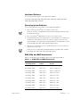
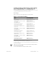
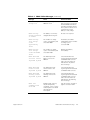
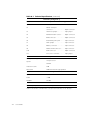
BIOS, ESM, and BMC Requirements
Table 1-1 details BIOS, ESM, and BMC requirements supported by DRAC II:
Table 1-1. BIOS, ESM, and BMC Requirements
support.dell.com
PowerEdge System
BIOS Version
Support
ESM/BMC Version
Support
PowerEdge 300
A00 or later
ESM not supported
PowerEdge 1300
A02 or later
ESM not supported
PowerEdge 1400
A01 or later
ESM not supported
PowerEdge 2300
A05 or later
ESM 3.14 or later
PowerEdge 2400
A00 or later
ESM 3.14 or later
PowerEdge 2450
A00 or later
ESM 5.21 or later
PowerEdge 2500
A00 or later
ESM 5.33 or later
PowerEdge 2550
A00 or later
ESM 5.33 or later
PowerEdge 4300
A02 or later
ESM 3.18 or later
PowerEdge 4350
A04 or later
ESM 3.18 or later
Introduction
1-3
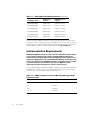
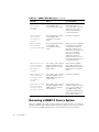
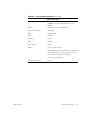
Table 1-1. BIOS, ESM, and BMC Requirements (continued)
PowerEdge System
BIOS Version
Support
ESM/BMC Version
Support
PowerEdge 4400
A00 or later
ESM 3.14 or later
PowerEdge 6300
A03 or later
ESM 3.17 or later
PowerEdge 6350
A00 or later
ESM 3.17 or later
PowerEdge 6400
A02 or later
ESM 5.26 or later
PowerEdge 6450
A02 or later
ESM 5.26 or later
PowerEdge 8450
A00 or later
BMC 0.16 or later
Check your system's BIOS or firmware version level during the boot routine. If the
version is not at the required level, you must update it to the correct version. You can
find instructions to update the BIOS and system management firmware revisions for
all PowerEdge systems on the Dell | Support website at support.dell.com.
Instrumentation Requirements
NOTICE: The DRAC II firmware version must be compatible with the proper
version of the managed node software (Dell OpenManage Hardware
Instrumentation Package [HIP] or Dell OpenManage Server Agent) to be a
supported configuration. If you install Dell OpenManage Server Agent 4.0
or later, you must also install DRAC II firmware version 2.4. Failure to properly match firmware and hardware can cause the DRAC II to work
improperly and adversely affect the console redirect feature.
Do not replace hardware. Update the DRAC II firmware to the level that supports that
managed node software version. The following table matches the correct firmware
versions to the correct managed node software versions.
Table 1-2. DRAC II Firmware Level and Matching Managed Node
Software Version
1-4
User’s Guide
DRAC II Firmware Version
Matching HIP or Server Agent Version
2.0
HIP 3.5
2.1
HIP 3.5
2.2
HIP 3.5.1
2.2.1
HIP 3.5.2
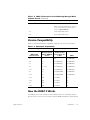
Table 1-2. DRAC II Firmware Level and Matching Managed Node
Software Version (continued)
DRAC II Firmware Version
Matching HIP or Server Agent Version
2.2.2
HIP 3.5.2 with Windows 2000 Patch
NOTE: The Windows 2000 patch for HIP 3.5.2
can be downloaded from the Dell | Support
website at support.dell.com.
2.3
Server Agent 4.0 or later
2.4
Server Agent 4.0 or later
Version Compatibility
Table 1-3 describes backwards compatibility support for the version 2.4 firmware:
Table 1-3. Backwards Compatibility
Management Station
DRAC II Web
Console Version
Network Node
Manager Special
Edition (NNM SE)
Version
Managed Node
Firmware
Version 2.4 and
Server Agent 4.0
or later
DRAC
1.5
1.3
No
Yes DRA Only
2.0
1.4
Yes DRA Only
Yes DRA Only
2.1
1.4
Yes DRA Only
Yes DRA Only
2.2
1.5, 1.5.1
Yes DRA Only
Yes DRA Only
2.2.1
1.5.2
Yes DRA Only
Yes DRA Only
2.3
1.6
Yes DWC/DRA
Yes DRA Only
2.3.1
1.6
Yes DWC/DRA
Yes DRA Only
2.3.2
N/A
Yes DWC
No
2.3.3
N/A
Yes DWC
No
2.4
N/A
Yes DWC
No
2.4.1
N/A
Yes DWC
No
How the DRAC II Works
The DRAC II comes with software modules that provide a set of operating system–
specific services. These services interface with the DRAC II hardware to allow in-band
support.dell.com
Introduction
1-5
configuration as well as console redirection to the out-of-band connection. The
following subsection describes the software modules used with the DRAC II.
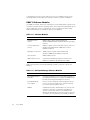
DRAC II Software Modules
The DRAC II software architecture is built upon several independent software modules that run under a specific operating system. The modules include hardware device
drivers, application services, management services, and user interfaces. Table
Table 1-4 summarizes the software modules for the DRAC II.
Table 1-4. Software Modules
Software Module
Description
Hardware Device
Drivers
DRAC II device driver under Windows NT,
Windows 2000, NetWare, and Red Hat Linux operating
systems
Console Redirection
Service
Graphics capture service and virtual mouse service for
Windows NT and Windows 2000; text mode for
NetWare and Linux
Management Services
SNMP extension agent under Windows NT,
Windows 2000, Novell NetWare, and Linux
User Interface
DRAC II Web Console
Address Book Server
Contains the IP address/telephone number of the
DRAC II for Windows NT and Windows 2000
Table 1-5 summarizes the Dell OpenManage software required to operate the
DRAC II.
Table 1-5. Dell OpenManage Software Modules
1-6
User’s Guide
Software Module
Description
Dell OpenManage IT
Assistant
A system management console program installed on
the management station to configure the DRAC II and
provide monitoring and management services.
Dell OpenManage
Server Agent
A set of services installed on the managed node systems to monitor the health of the system and notify
the console when a problem arises.
DRAC II
A hardware interface card that allows for remote management of systems, recreating the management
console in an external system or workstation and
allowing an administrator to access a system either via
a modem, over a local area network (LAN), or RS232.
Hardware device drivers allow applications and other system-level services to access
the DRAC II hardware. These drivers are operating-system specific.
The console redirection service provides the DRAC II with the graphics screen content to send to the remote console. When the system runs in text mode, the DRAC II
hardware captures the screen content automatically.
NOTE: For graphical redirection, the remote system is performing the redirection
process; therefore, a percentage of available microprocessor time is consumed when
the process is active. Dell recommends that you stop console redirection when not
needed so that the system is free for its normal tasks. In addition, Dell recommends
that the managed system run in a low-resolution graphics mode, such as 800 x 600,
and at a maximum of 256 colors to minimize the redirection task.
Management services are operating-system-specific services that support standard
management protocols. An enterprise network system is typically run by a management application. This application is based on certain management standards, such as
SNMP. Management through SNMP uses the in-band network.
The address book system resides on the management station and contains the Internet protocol (IP) address/phone number of the DRAC II. This module works under
Windows NT and Windows 2000.
DRAC II in the Dell OpenManage Environment
The user interfaces for the DRAC II are the Dell OpenManage IT Assistant for in-band
configuration and the DRAC II Web Console for out-of-band access. IT Assistant is
installed on the management console and is used to configure the DRAC II. Dell
OpenManage Server Agent must be installed on the managed node to configure the
DRAC II with IT Assistant.
When the System is Operational
When you access a remote system using the DRAC II, the DRAC II Web Console
gives you the following options for managing the system:
support.dell.com
•
The System Health window lets you view information such as the ambient
temperature of the DRAC II. This window also lists the firmware installed on the
system and the system’s BIOS version, as well as the current status of the DRAC
II’s battery, wall adapter voltage, and PCI bus voltage. The Set Refresh button in
this window allows you to adjust the monitoring polling period.
•
The System Information window specifies which system you are accessing and
the system’s BIOS version, baseboard, microprocessor(s), slots, ports, and
chassis.
•
The Event Log window keeps a record of remote system events, DRAC II
events, and POST logs.
Introduction
1-7
•
The Remote Access window contains the console redirect service, which allows
you to view the screen of the remote system. From this window, you can use the
management station’s mouse and keyboard to perform management functions
such as system reset, power off, power cycle, power on, and graceful shutdown.
You can also take a screen capture of the remote system and store the image as
a .bmp file or as a .txt file in text-only mode.
When the System is Nonoperational
An important feature of the DRAC II is its ability to notify an administrator when a system fails. To do this, the DRAC II sends an alert notification by dialing out to a
management station, sending a page, or sending an SNMP trap. After receiving the
alert, the administrator can connect to the DRAC II using the DRAC II Web Console
application and view the event log to determine the nature of the problem. The DRAC
II Web Console connects to the DRAC II via the 10 Mb/s network interface controller
(NIC) on a local area network/wide area network (LAN/WAN) or the optional PCMCIA
modem, both of which are located on the DRAC II. The DRAC II also captures the
screen at the time of the crash so that the administrator can possibly analyze the
cause.
To get the system up and running again, the administrator can perform a remote reset
or power cycle and view the boot process.
In addition, the RFB feature can be used to remotely boot the system to MS-DOS® or
to diagnostics diskettes when troubleshooting the system.
DRAC II Security
The following sections describe security features of the DRAC II.
Encrypted Password Authentication
DRAC II supports encrypted password authentication for connections via the DRAC II
NIC over TCP/IP and Point-to-Point Protocol (PPP) dial-in connections over the DRAC II
modem. The encryption method used within the PPP connection is the MD5
Challenge-Handshake Authentication Protocol (CHAP). MD5 is a one-way hash algorithm that encrypts American Standard Code for Information Interchange (ASCII) data.
Valid Login
The remote interface to the DRAC II requires a valid login. When establishing a
remote connection to a DRAC II, the user enters a user name and password at the
remote console. The password is then encrypted through the CHAP in the modem
connection, and the user name and encrypted password are sent to the DRAC II. The
DRAC II receives the user name and encrypted password and begins the process of
authentication. The saved password in the DRAC II (for this user name) is also
encrypted. It is compared with the encrypted password received from the remote
1-8
User’s Guide
user. If there is a match, the user is validated and access to the DRAC II is granted. No
other commands are recognized or processed by the authentication process until
validation occurs.
VT100 Connection Capabilities
The DRAC II provides VT100 connection capabilities. Password encryption is not used
for this type of connection. Since the VT100 connection is a direct-connect terminal
emulation, password encryption is not warranted. Terminal security is provided by
nonencrypted authentication of the user name and password. The firmware prevents
display of the password on the terminal. Only system power management features
(such as reset and power cycle) and text console redirection are provided via the
VT100 interface. Access to a graphical operating system is not available.
DRAC II Web Console
The DRAC II Web Console interface is the user interface for remote access to the
DRAC II. It is proprietary and provides no direct access to the host operating system
(OS). Typically remote access to the DRAC II is used when no administrator is locally
logged into the system. If an administrator does log on to the local system, operating
system access is protected by standard OS security measures. Users accessing the
DRAC II remotely use the CHAP and do not use the OS security. When a remote user
accesses a DRAC II and performs a console redirection, a pop-up notification box
appears at the system console stating that remote console redirection is occurring.
The notification box disappears within 5 seconds. In addition, it is possible for the
DRAC II to be remotely accessed through the Internet using a PowerEdge system as
a middle tier management station. For more information, see “Configuring Your Network to Access the DRAC II From the Internet.”
support.dell.com
Introduction
1-9
1-10
User’s Guide
CHAPTER 2
Installing the DRAC II
This chapter describes procedures for performing the following tasks:
•
•
Upgrading the basic input/output system (BIOS) on your system
•
Installing Dell OpenManage Server Agent and Dell OpenManage IT Assistant
Installing the Dell OpenManage Remote Assistant Card II (DRAC II) in a Dell
PowerEdge system
NOTICE: Read the installation instructions in this manual and in the system
Installation and Troubleshooting Guide before installing your DRAC II.
System Requirements
The DRAC II is compatible with Microsoft Windows NT, Windows 2000, Novell
NetWare 4.11 (with Service Pack 5 or later), NetWare 4.2, NetWare 5.0, NetWare 5.1,
NetWare 6.0, Red Hat Linux 7.0, Red Hat Linux 7.1, and Red Hat Linux 7.2. The DRAC
II requires the Dell OpenManage Server Agent to be configurable with Dell OpenManage IT Assistant.
NOTES: If a management station and a managed node both run Windows NT and are
part of a cluster configuration, they must use the same service pack.
If the managed node is running NetWare or Linux, the console redirect feature is text
only.
Upgrading the System BIOS
If you are adding the DRAC II to an existing system, you may need to update the
system’s BIOS prior to installing the DRAC II. Doing so ensures full support for the
DRAC II. For supported configurations, see Chapter 1, “Introduction.” For BIOS
requirements, see Table 1-1.
To update your system’s BIOS, perform the following steps:
1.
Obtain a copy of the most current version of your system’s BIOS.
Upgrades are available on the Dell | Support website at support.dell.com.
support.dell.com
Installing the DRAC II
2-1
2.
Launch the executable file and follow the prompts to create a BIOS flash
diskette.
3.
Insert the BIOS diskette and reboot the system.
The system should boot to the BIOS upgrade menu.
4.
Follow the instructions on the BIOS upgrade menu.
Installing the DRAC II
Perform the following steps to install the DRAC II.
CAUTION: Before you begin installing a DRAC II, carefully read the safety
instructions in your System Information document.
1.
Power down the system and all attached peripheral devices.
2.
Disconnect your system and peripherals from their power sources. Also
disconnect any telephone or telecommunication lines from the system.
Doing so reduces the potential for personal injury or shock.
CAUTION: The power supplies in your system or storage system may produce high voltages and energy hazards, which can cause bodily harm.
Only trained service technicians are authorized to remove the system
covers and access any of the components inside the system.
3.
Remove the system cover according to the instructions in your system
Installation and Troubleshooting Guide.
NOTICE: The PC Card modem cannot be inserted into the DRAC II while the
DRAC II is powered on. When installing a modem, you must first turn off the
system, disconnect the external power adapter from the DRAC II, and
remove the DRAC II from the system. Removing the DRAC II from the system
ensures that its integrated battery is not providing power to the circuitry on
the DRAC II.
4.
If your DRAC II kit included a Personal Computer Memory Card International
Association (PCMCIA) modem, install the modem in the socket on the DRAC II
mounting bracket.
Press firmly to seat the modem in the socket.
5.
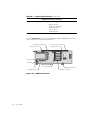
Determine the peripheral component interconnect (PCI) expansion slot in which
you install the DRAC II.
There is a designated slot in systems that support the Dell embedded system
management (ESM) connector. Only this slot has a space that accommodates
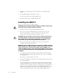
the ESM connector. The ESM connector must align with the corresponding connector in the system board. For example, in a PowerEdge 6300 system, the
DRAC II must be installed in slot PCI3 in order to align with the ESM connector
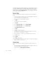
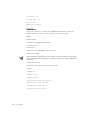
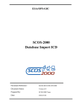
on the system board. See Figure 2-1 below and your PowerEdge system
2-2
User’s Guide
Installation and Troubleshooting Guide or documentation updates (if any) that
were provided with your DRAC II.
NOTE: On a PowerEdge 8450 there is no ESM connector on the system board.
Attach the IPMI connector on the system board. The ribbon cable for a PowerEdge 8450 is supplied in the DRAC II kit.
card-edge connector
ESM connector
IPMI
connector
Figure 2-1. DRAC II Connectors
6.
If another expansion card is already installed in the required slot, move the other
expansion card to another slot.
7.
Follow the instructions for installing PCI expansion cards in your PowerEdge system Installation and Troubleshooting Guide to install the DRAC II.
Ensure that the card-edge connector and the ESM connector are fully seated into
the system board.
8.
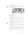
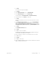
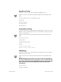
If you will be using a network connection with the DRAC II, attach the twistedpair cable to the RJ45 connector on the DRAC II. See Figure 2-2 for location of
the input/output (I/O) connectors.
NOTE: The DRAC II should be connected only to a switch or hub that supports a
10Base-T Ethernet connection.
9.
If you will be using a modem with the DRAC II, attach a modem adapter cable to
the PCMCIA modem and connect an analog telephone line to the adapter cable.
10. Replace the system cover.
11. If you have an optional external power adapter, plug it into the external power
input connector on the DRAC II. See Figure 2-2 for the location of this connector.
The DRAC II does not require the external power adapter; however, using it
allows the DRAC II to remain operational indefinitely when the system is off.
12. Reconnect the system and all associated peripheral devices to their AC power
sources and turn them on.
support.dell.com
Installing the DRAC II
2-3
external power input connector
PCMCIA socket
activity LED (amber)
RJ-45 connector
link LED (green)
Figure 2-2. DRAC II I/O Connectors
Installing the Software
After you install the DRAC II, you may need to install or upgrade Server Agent and IT
Assistant.
To take advantage of the new features in DRAC II, you may need to:
•
Install or upgrade the software for your managed node from the
Dell OpenManage Systems Management CD
•
Install or upgrade the software for your management station from the
Dell OpenManage Systems Management CD
•
Upgrade the DRAC II firmware
The following subsections provide information on installing the DRAC II software. The
DRAC II software contains two components:
•
Managed node software
A managed node is typically a server that contains a DRAC II, the appropriate version of Dell OpenManage Server Agent, and DRAC II agent. The DRAC II agent
consists of Windows services or Novell NetWare loadable modules (NLMs) or
Linux driver/daemons (depending on the operating system running on the system), that are automatically started when the system is booted.
•
Management station software
The management station is a system (typically a workstation running
Windows NT 4.0 or Windows 2000) that contains the appropriate versions of IT
Assistant and the DRAC II Web Console. The management station software consists of services and a browser-based user interface.
If you want to configure and manage the DRAC II using IT Assistant, use IT Assistant version 5.2 or later.
2-4
User’s Guide
Installing the Managed Node Software Under
Windows NT or Windows 2000
NOTE: The simple network management protocol (SNMP) service must be installed
on the managed node prior to installing the managed node software. The recommended SNMP Traps Community Name is public. The rights for the community
must be set to READ WRITE.
On Windows 2000, the drac2wdm.sys driver must be installed using Windows hardware wizard before installing the DRAC II agents. DRAC II agents installation fails if
the DRAC II driver is not present.
Dell now installs the DRAC II driver for Windows 2000 on your system. However, for
other operating systems (Novell NetWare, Microsoft Windows NT, and Red Hat
Linux), the drivers are installed with the DRAC II agents.
If you are installing or upgrading to Windows 2000, you must install the
drac2wdm.sys driver by performing the following steps:
1.
After the DRAC II is inserted in the system and Windows 2000 starts, the Found
New Hardware Wizard launches automatically if the DRAC II driver is not
installed.
2.
On the Found New Hardware Wizard dialog box, click Next. The Wizard displays these messages: This wizard will complete the installation
for this device: Base System Device.
3.
Click Next to search for a suitable driver for the device.
4.
Deselect Floppy Disk drives if it is checked, and select CD-ROM drives if it is
not already checked.
5.
Insert the Dell OpenManage Server Assistant CD or the Dell OpenManage Systems Management CD into the managed node CD drive.
6.
Click Next.
Autorun on the CD launches while the hardware wizard searches for drivers.
7.
Close the dialog that opens. The box might be titled Dell OpenManage Server
Assistant, Dell OpenManage Setup, or Choose Setup Language, depending
on what CD is used.
The hardware wizard finds drac2wdm.inf on the CD.
8.
Click Next.
9.
Click Finish.
NOTES: When installing the managed node software from Dell OpenManage Systems Management CD, the firmware of the DRAC II must be version 2.4 or later or
the DRAC II does not function properly. Upgrade the DRAC II firmware before or after
the installation of Server Agent. See “Firmware Installation,” found later in this
document.
support.dell.com
Installing the DRAC II
2-5
PowerEdge 2400, 2450, 4400, 6400, and 6450 users should upgrade their video drivers to revision A5393T (ATI version 4.00.1381.3254) for Windows NT and revision
A5.39.2 (ATI version 5.0.2195.3247) for Windows 2000. The drivers are available on
the Dell | Support website at support.dell.com. You might upgrade the video drivers
before or after installing Server Agent.
Express Setup
Perform the following steps to install the managed node software using Express
Setup:
1.
Assuming the DRAC II (and DRAC II driver for Windows 2000) is installed, insert
the Dell OpenManage Systems Management CD.
Autorun launches the Dell OpenManage Installation.
2.
Click Next.
The software license agreement displays.
3.
Click Accept.
4.
On the Select System Type screen, click Managed Node.
5.
On the Select Setup Type screen, click Express Setup.
The Installation Summary displays.
6.
Click Next.
7.
Click Yes to confirm the installation.
The application being installed is highlighted during installation and checked
when installation of that application is complete.
8.
After the installation is complete, you are prompted to reboot your system.
9.
Click Yes to reboot.
10. Click Finish.
11. Click OK to confirm reboot.
12. Go to “Installing the Management Station Software for Windows NT or Windows
2000,” found later in this document.
Custom Setup
Perform the following steps to install the managed node software using Custom
Setup:
1.
Assuming the DRAC II (and DRAC II driver for Windows 2000) is installed, insert
the Dell OpenManage Systems Management CD.
Autorun launches the Dell OpenManage Installation.
2-6
User’s Guide
2.
Click Next.
The software license agreement displays.
3.
Click Accept.
4.
On the Select System Type screen, click Managed Node.
5.
On the Select Setup Type screen, click Custom Setup.
You are prompted for a Destination Drive and Destination Directory.
6.
Accept the defaults or click Browse to change them.
7.
Click Next.
The system automatically selects services for which it detects the necessary
hardware.
8.
At the Management Node Software screen, ensure that Remote Management and Dell OpenManage Server Administrator are selected. Deselect
Storage Management, Diagnostic Service, and Other Management Agents
unless you want to install them. They are not required for the DRAC II.
9.
Click Next.
The Installation Summary displays.
10. Click Next.
11. Click Yes to confirm the installation.
The application being installed is highlighted during installation and checked
when installation of that application is complete.
12. After the installation is complete, you are prompted to reboot your system.
13. Click Yes to reboot.
14. Click Finish.
15. Click OK to confirm reboot.
16. Go to “Installing the Management Station Software for Windows NT or Windows
2000,” found later in this document.
support.dell.com
Installing the DRAC II
2-7
Installing the Managed Node Software Under
NetWare 5.x and NetWare 6.0
To install the DRAC II agent on a managed node running Netware 5.x and
NetWare 6.0 perform the following steps:
1.
Insert the Dell OpenManage Systems Management CD.
2.
At the NetWare prompt, type CDROM.
NetWare responds with the CD volume label.
3.
Type NWCONFIG.
4.
Press <Enter>.
5.
Press the down arrow to Product Options.
6.
Press <Enter>.
7.
Press the up arrow to Install a Product Not Listed.
8.
Press <Enter>.
9.
Press <F3> to specify a path.
10. Type in the volume label of the CD and the path to the DRAC II agent:
Appcd30_a00:\Netware.
11. Press <Enter>.
12. Press the down arrow to highlight DRAC Agent.
13. Press <Enter> to check the box.
14. Press <F10>.
15. The following prompt appears: Do you want to change the default
security settings for the Dell OpenManage Server Agent?
16. Answer No to keep the default password “calvin,” or answer Yes to choose a
new password.
17. Press <Enter>.
18. Press any key to continue.
19. Press <Esc> two times.
20. Press <Enter> to exit nwconfig.
21. At the prompt, type Restart Server.
22. Press <Enter>.
2-8
User’s Guide
Installing the Managed Node Software Under Red Hat
Linux 7.0, Red Hat Linux 7.1, or Red Hat Linux 7.2
The following subsections provide instructions for installing managed node software
on systems running Red Hat Linux versions 7.0, 7.1, and 7.2.
Kernel Support
Table 2-1 identifies the kernels supported by the following software:
Table 2-1. Kernels Supported by DRAC II
System
Kernel Package Name
Red Hat Linux 7.0 (single processor)
kernel-2.2.16-22
DRAC-RH70-UP-2.4-3
DRAC-RH70-Common-2.4-8
Red Hat Linux 7.0 (symmetric multiprocessor [SMP])
kernel-smp-2.2.16-22
DRAC-RH70-SMP-2.4-3
DRAC-RH70-Common-2.4-8
Red Hat Linux 7.0 (enterprise)
kernel-enterprise-2.2.16-22
DRAC-RH70-EN-2.4-3
DRAC-RH70-Common-2.4-8
Red Hat Linux 7.1 (single processor)
kernel-2.4.3-6
DRAC-RH71-SBE-UP-2.4-1
DRAC-RH71-Common-2.4-5
Red Hat Linux 7.1 (symmetric multiprocessor [SMP])
kernel-smp-2.4.3-6
DRAC-RH71-SBE-SMP-2.4-1
DRAC-RH71-Common-2.4-5
Red Hat Linux 7.1 (enterprise)
kernel-enterprise-2.4.3-6
DRAC-RH71-SBE-EN-2.4-1
DRAC-RH71-Common-2.4-5
Red Hat Linux 7.2 (single processor)
kernel-2.4.7-10
DRAC-Driver-2.4.1-3
DRAC-Common-2.4.1-2
Red Hat Linux 7.2 (symmetric multiprocessor [SMP])
kernel-smp-2.4.7-10
DRAC-Driver-2.4.1-3
DRAC-Common-2.4.1-2
Red Hat Linux 7.2 (enterprise)
kernel-enterprise-2.4.7-10
DRAC-Driver-2.4.1-3
DRAC-Common-2.4.1-2
You can verify your kernel by running the command uname -r.
To install the DRAC II on a system running the Red Hat Linux operating system, perform the following steps.
NOTES: You must insert the DRAC II into the system before installing the DRAC II
Red Hat Package Manager (RPM).
You must install SNMP before installing the DRAC II software.
support.dell.com
Installing the DRAC II
2-9
NOTICE: You must uninstall any pre-existing DRAC II software installations.
1.
Determine what DRAC II RPMs are already installed by typing the following command: rpm -qa | grep DRAC.
2.
Delete any RPMs that are listed by typing the following command: rpm -e
<DRAC-RPM-name>.
For example:
rpm -e DRAC-RH71-SBE-UP-2.4-1
NOTE: You must first delete any common RPMs before deleting other RPMs.
3.
Start the GNOME desktop if it is not already open. At the prompt, type startx.
4.
Press <Enter>.
5.
Close the GNOME hint box if it appears.
6.
Close any warning boxes that appear.
7.
Insert the Dell OpenManage Systems Management CD.
The file manager should appear. If not, launch file manager. The Location box in
file manager should show /mnt/cdrom.
8.
Double-click the start.sh icon.
Dell OpenManage Setup launches.
9.
Click Next.
The software license agreement displays.
10. Click Accept.
11. Click Express Setup.
The Installation Summary displays.
12. Click Next.
13. Click Yes to install selected components.
14. You are prompted to reboot your system.
15. Click Finish.
16. Click OK to confirm reboot.
17. Go to “Installing the Management Station Software for Windows NT or Windows
2000,” found later in this document.
2-10
User’s Guide
DRAC II Software Basics for Red Hat Linux
The following list describes basic software information for DRAC II with Red Hat
Linux:
•
To display the current setting of the DRAC II, type the following command:
racconf
•
To verify that DRACSnmp (SNMP extension agent for DRAC II) is loaded, type the
following command:
ps -ax | grep DRACSnmp
•
To verify that DRACd (DRAC II daemon) is loaded, type the following command:
ps -ax | grep DRACd
•
To start, stop, or restart DRACSnmp, type the following command:
/etc/rc.d/init.d/DRACSnmp [start, stop, restart]
•
To start, stop, or restart DRACd, type the following command:
/etc/rc.d/init.d/DRACd [start, stop, restart]
NOTE: Both DRACSnmp and DRACd are started automatically when you install the
package, and they are stopped automatically when you uninstall the package.
•
To determine which version you have installed, use a package management tool
such as GnoRPM, or use the RPM query command (rpm -q) to determine if the
package is installed.
For example: rpm -q DRAC-RH70-SMP
•
To determine which files were installed and where they are located, type the following command: rpm -ql <package name>
The binaries and RPMs are installed as shown in Table 2-2.
Table 2-2. Installed Files
support.dell.com
File Name
Location
racconf
/usr/sbin/
DRACd
/usr/sbin/
DRACSnmp
/usr/sbin/
Mrmibmain
/usr/sbin/
rac.o
/lib/modules/[kernelversion-number]/misc/
racconf.ini
/etc/
rc.modules
/etc/rc.d
omsasync
/usr/sbin/
Installing the DRAC II
2-11
The RPM installs the startup script for the DRAC II daemon and DRACSnmp in
the following directories:
/etc/rc.d/rc3.d
/etc/rc.d/rc5.d
/etc/rc.d/rc6.d
/etc/rc.d/rc0.d
To remove a package, type the following command: rpm -e [package name]
Open Issues With DRAC II Under Red Hat Linux
DRAC II is supported on precompiled kernels that are a part of the Red Hat Linux 7.0,
Red Hat Linux 7.1, and Red Hat Linux 7.2 distribution. DRAC II is not supported on
recompiled kernels with other configuration options (for example, kernels configured
for performance tuning purposes).
Linux might fail to load when started on recompiled kernels. If a “failure to load”
occurs, you must either restore the kernel and modules from backup, or you must
reinstall the kernel from the Red Hat RPM packages.
Installing the Management Station Software for
Windows NT or Windows 2000
NOTES: If you have the DRAC II Web Console version 2.3.1 or earlier installed, you
must uninstall it before performing an upgrade. Uninstall the console using Add/
Remove Programs. You must then restart the system.
Microsoft Internet Explorer 4.0 or later must be installed before the installation of the
management station software on Windows NT/Windows 2000 Management
Stations. Management Station software installation fails if Internet Explorer is not
present.
Custom Setup
NOTE: Dell recommends that you use Custom Setup rather than Express Setup
because Express Setup installs additional software that is not required for DRAC II.
1.
Insert the Dell OpenManage Systems Management CD.
Autorun launches Dell OpenManage Installation.
2.
Click Next.
The software license agreement displays.
3.
Click Accept.
NOTE: If your are installing the management station software on any system other
than a PowerEdge system, skip step 4 and continue with step 5.
2-12
User’s Guide
4.
On the Select System Type window, click Mgmt Station.
5.
On the Select Setup Type window, click Custom Setup.
6.
You are prompted for a Destination Drive and Destination Directory.
7.
Accept the defaults or click Browse to change them.
8.
Click Next.
9.
On the Management Station Software screen, select Remote Management
and IT Assistant.
Array Manager selects automatically with IT Assistant.
10. Deselect Other Management Applications unless you want to install them. The
applications are not required for DRAC II.
11. Click Next.
The Installation Summary displays.
12. Click Next.
13. Click Yes to confirm the installation.
The application being installed is highlighted during installation and checked
when installation of that application is complete.
14. You are prompted to reboot your system.
15. Click Yes to reboot.
16. Click Finish.
17. Click OK to confirm reboot.
NOTE: Remote Access Service (RAS) has to be installed and the service running, and
dial-up networking must be configured, if you plan to use a modem for out-of-band
management.
18. If you are going to install RAS, see “Remote Access Service Setup for Windows NT
Management Stations,” in the following section for the appropriate operating system. If you are not using RAS, go to Chapter 3, “Configuring and Using the
DRAC II.”
Remote Access Service Setup for Windows NT
Management Stations
To set up RAS for Windows NT management station(s), perform the following steps:
support.dell.com
1.
Click the Start button, point to Settings—> Control Panel.
2.
Double-click the Network icon and click the Services tab.
3.
Highlight Remote Access Service (if Remote Access Service is not already
listed, add it to the list using system default settings) and click Properties.
Installing the DRAC II
2-13
4.
At the Remote Access Setup dialog box, highlight a port entry in the list (if necessary, add an available modem), and click Configure.
5.
At the Configure Port Usage dialog box, click Dial-out and Receive calls, and
then click OK.
6.
At the Remote Access Setup dialog box, click Network.
7.
At the Network Configuration dialog box, perform the following steps:
a.
Under Dial-out Protocols, select the TCP/IP check box only.
b.
Under Server Settings, Allow Remote Clients Running, select the TCP/IP
check box only.
c.
Under Encryption Settings, select the Allow Any Authentication Including Clear Text check box. Do not select the Enable Multilink check box.
8.
Click Configure for TCP/IP.
9.
At the RAS Server TCP/IP Configuration dialog box, perform the following
steps:
a.
Under Allow Remote TCP/IP Clients to Access, select Entire Network or
This Computer Only, depending on the level of security that you require.
b.
Assign TCP/IP addresses as appropriate. Do not select the Allow Remote
Clients to Request a Predetermined IP Address check box.
c.
Click OK.
d.
At the Network Config dialog box, click OK.
e.
Click Continue at the Remote Access Setup dialog box.
f.
Close the Network window.
g.
Click Yes to restart your system.
Dial-Up Networking Setup for Windows NT Management
Stations
To set up dial-up networking for Windows NT management station(s), perform the following steps:
1.
2-14
User’s Guide
Click the Start button, point to Programs—> Accessories—> Dial-up
Networking.
2.
At the Dial-Up Networking dialog box, click New under Phonebook entry to
dial.
•
•
3.
If the New Phonebook Entry dialog box appears, proceed to step 3.
If the New Phonebook Entry Wizard dialog box appears, type drac-ppp in
the Name the new phonebook entry field, check the I know all about
phonebook entries... check box, and click Finish. Proceed to step 3b.
At the New Phonebook Entry dialog box, click the Basic tab and perform the following steps:
a.
In the Entry Name field, type drac-ppp.
b.
Select the Use Telephony Dialing Properties check box.
c.
In the Dial Using field, select the same modem you specified in step 4 of
the previous section, “Remote Access Service Setup for Windows NT Management Stations.”
Do not select the Use another port if busy check box.
d.
4.
At the Modem Configuration dialog box, ensure Initial speed (bps) is set correctly, select the Enable Hardware Flow Control check box, select Enable
Modem Control (optional) and Enable Modem Compression (optional), enable
or disable the modem speaker (optional), and click OK.
5.
At the New Phonebook Entry dialog box, click the Server tab and perform the
following steps:
6.
support.dell.com
Click Configure....
a.
In the Dial-Up Server Type field, select PPP: Windows NT, Windows 95
Plus, Internet.
b.
Under Network Protocols, make sure only the TCP/IP check box is
selected.
c.
Select the check boxes for Enable Software Compression and Enable PPP
LCP extensions.
d.
Click TCP/IP Settings....
At the PPP TCP/IP Settings dialog box, perform the following steps:
a.
Click Server Assigned IP Address.
b.
Click Server Assigned Name Server Addresses.
c.
Select the check boxes for Use IP Header Compression and Use Default
Gateway on Remote Network.
d.
Click OK.
Installing the DRAC II
2-15
7.
At the New Phonebook Entry dialog box, click the Script tab and confirm the
default settings:
•
•
None selected for After dialing (login).
None displayed in the Run this script: field.
8.
Click the Security tab and click Accept Any Authentication Including Clear
Text.
9.
Click the X.25 tab, make sure Network is set to (none), and click OK.
10. At the Dial-Up Networking dialog box, click Close.
11. Restart the system.
Remote Access Service Setup for Windows 2000
Management Stations
To set up Remote Access Service for Windows 2000 management station(s), perform
the following steps:
1.
Right-click My Computer.
2.
Click Manage.
3.
Double-click Services and Applications.
4.
Double-click Services.
5.
If the Service Startup type is not Automatic, right-click Routing and Remote
Access. (To determine if the startup type is automatic, look for the word “Automatic” in the Startup Type column).
6.
Click Properties.
7.
Click the drop-down box in the Startup Type field.
8.
Click Automatic.
9.
Click Apply.
10. Click OK.
11. If Routing and Remote Access service is not started, right-click on the service
and click Start. (To determine if the service is started, look for the word
“Started” in the Status column). Service should start automatically on subsequent restarts.
12. If DRAC CardObject Server is not started, right-click the service and click Start.
(To determine if the service is started, look for the word “Started” in the Status
column). Service should start automatically on subsequent restarts.
2-16
User’s Guide
Dial-Up Networking Setup for Windows 2000
Management Stations
To set up dial-up networking for Windows 2000 management station(s), perform the
following steps:
1.
Click the Start button, and point to Programs—> Accessories—>
Communications—> Network and Dial-up Connections.
2.
Double-click Make New Connection.
3.
In the Network Connection Wizard window, choose Next.
4.
If required, complete the Location Information and specify that location on the
Phone and Modem Options screen.
5.
Choose Dial up to private network.
6.
Click Next four times.
7.
Type the following name for the connection: drac-ppp.
8.
Click Finish.
9.
Restart the system.
Firmware Installation
If you ordered a DRAC II with your system, Dell installed the version 2.4 firmware. If
you are adding the DRAC II or upgrading, you can upgrade the firmware on the DRAC
II by using a firmware flash diskette for the version of firmware you want to load to
the DRAC II. Any DRAC II can be upgraded to version 2.4 with a firmware upgrade.
NOTICE: The DRAC II firmware version must be compatible with the proper
version of the managed node software (Dell OpenManage Hardware
Instrumentation Package (HIP) or Dell OpenManage Server Agent) to be a
supported configuration. Failure to properly match firmware and hardware
can cause the DRAC II to work improperly and adversely affect the console
redirect feature. See Table 1-2 for a list of firmware versions with supported HIP and Server Agent versions.
If you do not have a version 2.4 or later firmware flash diskette, you can download the
firmware file from the Dell | Support website at support.dell.com. When you run the
file, you receive a series of prompts to guide you through the creation of a firmware
flash diskette.
support.dell.com
Installing the DRAC II
2-17
After you have created the diskette or if you are using the diskette that came with
your DRAC II, follow these steps to update your firmware:
1.
Insert the diskette in the diskette drive and restart the system.
The software on the diskette automatically flashes the new firmware to the
DRAC II.
2-18
User’s Guide
2.
When the flash completes, remove the flash diskette.
3.
Reboot the system.
CHAPTER 3
Configuring and Using the
DRAC II
The Dell OpenManage Remote Assistant Card II (DRAC II) helps you monitor your Dell
system environment by extending the system management capabilities of the Dell
OpenManage IT Assistant and the Dell OpenManage Server Agent. Using the
DRAC II Web Console, you can remotely monitor and manage your PowerEdge system through a network or modem connection.
For complete information on installing and using the Server Agent, see the
Dell OpenManage Server Agent User’s Guide. For complete information on installing,
configuring, and using the IT Assistant, see the Dell OpenManage IT Assistant User’s
Guide. You can find both User’s Guides on your documentation CD. For the latest
information on configuring and using the DRAC II, see the dracread.txt file on the
Dell OpenManage Systems Management CD.
This chapter describes procedures for performing the following tasks:
support.dell.com
•
•
•
•
•
•
•
•
Adding a DRAC II administrator using IT Assistant
•
Access to the DRAC II through the Internet
Configuring the network properties of the DRAC II with IT Assistant
Configuring the modem properties of the DRAC II with IT Assistant
Configuring DRAC II alerts with IT Assistant
Configuring the DRAC II using the racconf utility
Using the DRAC II Web Console for server management
Connecting to the serial port
Using the Remote Floppy Boot utility for remotely booting a managed node from
a diskette in the management station
Configuring and Using the DRAC II
3-1
Configuring the DRAC II in the
Dell OpenManage Environment
The following subsections provide information on configuring the DRAC II.
Adding a DRAC II Administrator
The DRAC II holds information for up to sixteen administrators. The DRAC II provides
out-of-band security by requiring an administrator to provide a user name and password prior to establishing a remote connection. The DRAC II also provides paging
services to notify administrators if the system crashes, loses power, or experiences a
list of other events. In addition, you can enter an optional callback number to force the
DRAC II to hang up on a modem connection and call back to the preconfigured number as an extra security measure.
NOTE: The DRAC II does not have a default user name and password. To establish a
remote connection using the DRAC II Web Console, you must assign a user name
and password. The defaults for the IT Assistant (“root” and “calvin”) do not work
unless you assign them.
To create a DRAC II administrator, perform the following steps:
1.
Launch IT Assistant by clicking the Start button and pointing to Programs—>
Dell OpenManage Applications—> IT Assistant—> IT Assistant.
2.
At the Security Warning window, click Yes.
If the following prompt appears: Do you want to install the required
components for Dell OpenManage IT Assistant?, click Yes.
3.
At the Security Warning window, click Yes.
4.
At the Logon Information window, select Read/Write and enter a Password. If
no password is set up, the default is a blank password.
5.
Click OK.
You are prompted to configure Discovery.
6.
Click Yes.
7.
At the Default Discovery Configuration window, accept the defaults and click
OK.
8.
At the Subnet Discovery window, click Add.
9.
At Subnet Type, click the drop-down arrow and select the appropriate subnet
type for your network and enter the appropriate information in the block(s) that
follow.
For example, if you select IP Address, enter 120.120.120.2 or the IP address for
the node you are trying to configure.
10. Accept the defaults for the remainder of the screen and click OK.
3-2
User’s Guide
11. Click Close at the Subnet Directory window.
12. Click Servers.
13. Double-click the Host Name of the system to be configured.
14. Click the Users tab.
15. Click Add.
16. Log in if the Login dialog box displays. The default login for the agent installed on
the server with the DRAC II is:
Username: root
Password: calvin
If you enter your own password during setup of the DRAC II agents, the calvin
default is overwritten.
17. Click OK.
18. Enter a user name in the Name field.
19. Enter a new password in the New Password field.
20. Enter the new password again.
21. Click the Configure DRAC User check box.
22. Enter a telephone number in the Session Callback Number field.
The session callback number allows the system to receive a call, hang up, and
then call the console back at an assigned number. This security feature limits
remote access to a single telephone number to ensure that the system only
responds to calls from selected consoles. If a callback number is not entered, the
system can respond to calls from any console. This feature is only applicable if
you are using a modem.
23. Select the type of pager you have from the Pager Type drop-down box.
If a pager type is selected, DRAC II issues a page to the user if DRAC II generates
an event that meets the maximum pager severity level.
NOTE: The DRAC II does not page on an event if the system is being “actively managed” through the DRAC II. If any user has a remote session established with the
DRAC II during an event, the DRAC II Web Console displays a flashing red icon in the
user interface but no page is issued. All remote sessions with the DRAC II must be
closed for paging to occur.
24. Enter a service provider telephone number in the Service Provider field.
The telephone number of the service provider for alphanumeric paging goes
here. If numeric paging was selected from the Pager Type drop-down box, this
box should remain blank. If the modem line to which the DRAC II connects for
paging requires a number to be dialed to connect to an outside line, this number
support.dell.com
Configuring and Using the DRAC II
3-3
should be separated from the telephone number by a comma. Example:
9,5551212.
25. Enter a pager number in the Pager Number field.
For alphanumeric paging, enter the unique pager number or personal identification number (PIN) required by the service provider to identify your pager.
Example: 12345.
For numeric paging, enter the pager number. Again, the number dialed to connect to an outside line (if required) should be separated by a comma and four
trailing commas should follow the main telephone number. The trailing commas
are required to give the paging service time to answer and respond before the
customized pager string is sent. Each comma represents approximately one second of delay. Example: 9,5551212,,,,. If your numeric pager requires a PIN
number, an example might be 9,5551212,,,,12345,,,,. Adjusting the actual number of commas may be required based on the individual service provider.
26. Select the severity level from the Minimum Pager Severity Level drop-down
box.
27. Enter a pager string in the Customized Pager String field, if desired.
For example, enter 911 for a numeric pager or a system name for an alphanumeric pager.
28. Click OK.
The name you entered appears in the Username box with a telephone icon next
to the name to indicate remote access privilege.
Configuring the Network Properties of the DRAC II
The DRAC II contains an integrated 10Base-T Ethernet network interface controller
(NIC) and supports Transmission Control Protocol/ Internet Protocol (TCP/IP). The NIC
has a default address of 10.0.0.1 and a default gateway of 0.0.0.0.
NOTES: If the DRAC II is configured to the same IP address as another NIC on the
same network, an IP address conflict occurs. The DRAC II stops responding to network commands until the IP address is changed on the DRAC II. The DRAC II must be
changed even if the IP address conflict is resolved by changing the other network
interface card.
Changing the IP address of the DRAC II causes the DRAC II to reset. If simple network management protocol (SNMP) polls the DRAC II before the card initializes, a
temperature warning is logged because the correct temperature is not transmitted
until the card is initialized.
To configure the network properties of the DRAC II, perform the following steps:
3-4
User’s Guide
1.
On the IT Assistant menu, click Configuration.
2.
From the submenu, click Remote Access Hardware.
3.
Click the Host Name of the system housing the DRAC II to be configured.
4.
Click the Network tab.
5.
Enter the required information in the IP Address, Subnet Address and Default
Gateway fields of the DRAC II (not the system).
6.
Click Save.
NOTE: To save the IP address to the DRAC II, you must first reset the DRAC II. If
SNMP polls the DRAC II before the card is initialized, a temperature warning is
issued. The correct temperature is not transmitted until the card completes the
reset.
7.
Click Yes.
The reset takes a couple of minutes for the DRAC II to reinitialize.
Configuring the Modem Properties of the DRAC II
Configuring the DRAC II modem properties is an optional feature; however, a modem
is required.
To configure the modem properties of the DRAC II, perform the following steps:
1.
On the IT Assistant menu, click Configuration.
2.
From the submenu, click Remote Access Hardware.
3.
Click the Host Name of the system housing the DRAC II to be configured.
4.
Click the Modem tab.
5.
Select Pulse or Tone in the Dial Mode field.
6.
Enter an initialization string in the Initialization String field.
If you want to use the DRAC II default string, then leave this field empty.
7.
Select a baud rate from the Baud Rate drop-down menu.
8.
Click Save.
NOTE: To save the modem properties to the DRAC II, you must first reset the
DRAC II. If SNMP polls the DRAC II before the card is initialized, a temperature
warning is issued. The correct temperature is not transmitted until the card completes the reset.
9.
Click Yes.
It takes a few minutes for the DRAC II to reinitialize.
support.dell.com
Configuring and Using the DRAC II
3-5
Configuring the Alert Properties of the DRAC II
The DRAC II can be configured to respond to alert conditions from the system’s
embedded server management (ESM) hardware or to other conditions such as operating system crashes or power failures. In addition to paging, the DRAC II can send an
SNMP trap to preconfigured destinations. The DRAC II can also dial-out to a remote
system and transfer the event information.
NOTE: The DRAC II does not alert on an event if the system is being “actively managed” through the DRAC II. If any user has a remote session established with the
DRAC II during an event, the DRAC II Web Console displays a flashing red icon in the
user interface but no alerts are issued. All remote sessions with the DRAC II must be
closed for alerting to occur.
To configure the alert properties of the DRAC II, perform the following steps:
1.
On the IT Assistant menu, click Configuration.
2.
From the submenu, click Remote Access Hardware.
3.
Click the Host Name of the system housing the DRAC II to be configured.
4.
Click the Alerts tab.
5.
Enter an IP address in the Destination IP Address field of a management station
if you want the DRAC II to send SNMP traps to a management station when an
event occurs.
6.
Enter the name in the Community Name field to which to send the trap.
7.
Enter the number of a management station in the Dial-Out Number field if you
want the DRAC II to call a management station and transfer event information.
If the modem line to which the DRAC II connects for paging requires a number to
be dialed to connect to an outside line, separate this number from the telephone
number by a comma. Example: 9,5551212.
8.
Click Add.
Configuring Your Network to Access the DRAC II From the
Internet
To access the DRAC II through the Internet, you must first set up a PowerEdge system to act as an address book server (middle-tier management station).
Requirements for Management Stations to Access DRAC II From the
Internet
To access DRAC II from the Internet, management stations must have the following
components installed:
•
•
3-6
User’s Guide
Windows NT or Windows 2000 operating system
HTTP server (Microsoft Internet Information Services (IIS) or equivalent)
•
•
Microsoft Internet Explorer 4.0 or later (Netscape not currently supported)
Two network interface controllers (NICs) or one NIC and a modem
NOTES: If you plan to use a modem to connect to DRAC II on the managed node,
the management station must have the Remote Access Server (RAS) — both
Routing and RAS for Windows 2000 — installed with dialup networking properly
configured.
For Internet connections, the DRAC II client connects to the DRAC II command
server located on the management station. If the management station is behind
a firewall, open the following ports: 6001 (used by the client to communicate with
the DRAC II), 6003 (used by the client to communicate with the address book
service), and 6005 (used for the dialup connection).
For Intranet and virtual private network (VPN) connections where no http server is
used, the DRAC II client does not go through the DRAC II command server to
connect to the DRAC II or address book service. If the management station is
behind a firewall, open the following ports: 5001 (used by the client to communicate with the DRAC II), 5003 (used by the client to communicate with the
address book service), and 5005 (used for the dialup connection).
Setting Up a System as an Address Book System
To set up a system as an address book system, perform the following steps:
1.
Connect one NIC to the Internet and the other to the LAN for the managed
nodes.
-ORConnect the NIC to the Internet and the modem to an analog telephone line.
support.dell.com
2.
Using the Dell OpenManage Systems Management CD, install Remote Management from the Management Station Applications menu.
3.
Restart the system.
4.
Launch the DRAC II Web Console by clicking the Start button and pointing to
Programs—> Dell OpenManage Applications—> Dell Remote Assistant—>
DRAC II Web Console.
5.
Click New Session to open the address book.
6.
In the Favorite Management Stations box, double-click the (LOCAL) management station icon.
7.
In the address book, click Add.
8.
Add the Server Name and IP Address of the managed node (or the modem
number of the DRAC II) and click OK. Input address book information for all the
managed nodes on the LAN.
9.
Open a cmd window and ping all the IP addresses in the address book to verify
that each is receiving messages. If the ping request times-out, verify that your
DRAC II network connections and IP addresses are correct.
Configuring and Using the DRAC II
3-7
10. From the DRAC II Web Console, double-click a server name in the address book.
11. Enter the User Name and Password to verify that you are able to connect to the
DRAC II.
When four selections appear in the left side of the console window, the connection has been made successfully. Verify each managed node.
12. Close the DRAC II Web Console.
Configuring a Desktop, Laptop, or PowerEdge System as the DRAC II
Web Console
To set up a system to act as the DRAC II Web Console, perform the following steps.
NOTE: The DRAC II Web Console feature is not supported on Windows 9x.
1.
Connect the NIC to the Internet, or the modem to an analog telephone line.
2.
Using the Dell OpenManage Systems Management CD, install Remote Management from the Management Station Applications menu.
3.
Restart the system.
4.
Connect to your Internet service provider (ISP).
5.
Launch the DRAC II Web Console by clicking the Start button and pointing to
Programs—> Dell OpenManage Applications—> Dell Remote Assistant—>
DRAC II Web Console.
6.
Click New Session to open the address book.
7.
In the Favorite Management Station dialog box, click Add New Station.
8.
In the Add New Management Station dialog box, type http:// and the IP
address or system name of the address book server established in the previous
section.
9.
Click OK.
A globe icon with the URL for the dress book server appears.
10. Double-click the new icon.
The address book you established in the previous section appears in the Address
Book box.
11. Double-click the server name of the managed node you want to remotely
manage.
12. Enter the requested information in the User Name and Password fields.
13. Click OK.
You should now be able to connect to the DRAC II and remotely manage the managed
node.
3-8
User’s Guide
Configuring the DRAC II Outside the Dell
OpenManage Environment
The simplest and fastest way to configure the DRAC II is with IT Assistant. However,
for the Windows and Linux operating systems, the DRAC II can also be configured
using the racconf utility. The racconf utility is installed along with the DRAC II agents
on the managed node. See Appendix B, “Racconf Utility,” for a detailed explanation
of the racconf utility.
If the racconf utility is used to configure the DRAC II, IT Assistant does not recognize
any of the users created with racconf unless the OMSASync utility is run after racconf
to synchronize the DRAC II database and the Dell OpenManage Server Agent
database.
NOTICE: If IT Assistant connects to a managed node on a server and the
DRAC II was configured with racconf, IT Assistant deletes all user IDs from
the DRAC II when the User’s tab on IT Assistant is selected unless
OMSASync is used. OMSASync must be used every time racconf is used.
Using the Racconf Utility Under Windows NT and
Windows 2000
1.
Click the Start button and point to Find (or Search)—> Files or Folder.
2.
Enter racconf.ini in the Named file field.
3.
Click Find Now.
4.
When the file is located, double-click the file icon to open racconf.ini in Notepad.
5.
Scroll down to the NetConfig group.
NOTE: Ensure there are no spaces or other characters between the equal sign (=) and
the start of the address. Do not press <Enter> after typing in the address. Use the
arrow keys to position the cursor to the next line.
6.
Change the IpAddr from 10.0.0.1 (the factory default) to the desired IP address
for the DRAC II.
7.
Change the SubNetMask from 0.0.0.0 (the factory default) to the desired subnet
mask address for the DRAC II.
8.
Change the GatewayAddr from 0.0.0.0 (the factory default) to the desired gateway address for the DRAC II.
9.
Scroll to the AdminEntryxx groups.
NOTE: Ensure there are no spaces or other characters between the equal sign (=) and
the start of the name and password. Do not press <Enter> after typing. Use the
arrow keys to position the cursor to the next line. Administrator name and password
should be lowercase.
10. Enter the administrator alias for AdminEntry0.
support.dell.com
Configuring and Using the DRAC II
3-9
11. Enter the password for AdminEntry0.
NOTE: There must be at least one DRAC II administrator to log in to the DRAC II. No
entries are required for the other 15 administrators but AdminEntry1 through
AdminEntry15 can be configured for additional DRAC II administrators.
12. See Appendix B, “Racconf Utility,” for details on configuring the other parameters of the AdminEntryxx group and the other configurable groups in the
racconf.ini file. Configure other parameters and groups as desired.
13. Close Notepad.
14. Click Yes to save the changes.
15. Copy the racconf.ini file to the root directory, which is usually c:\.
16. Click the Start button and then click Run.
17. Type cmd in the Run field.
18. Click OK.
19. Change the drive letter in the cmd.exe window to C: if the drive letter is not c:\.
20. At the prompt, type racconf /c racconf.ini.
21. Press <Enter>.
After a few seconds the response Loading information from INI file
to the DRAC card... appears. Next, a request to reset the card appears. The
card must be reset for the new settings to take effect.
22. At the prompt, type racconf /r.
23. Press <Enter>.
The response Resetting Card appears.
Resetting the card takes 1.5 to 2 minutes. The reset is complete when the
response Reset Complete appears.
24. Type omsasync at the command line prompt to run the OMSASync utility which
syncs the DRAC II user IDs with Server Agent (for more information on using the
OMSASync utility, see your syncread.txt file.)
25. Press <Enter>.
Using the Racconf Utility Under NetWare
1.
At the server prompt, type:
unzip sys:\system\dell\omsa\racconf.zip.
3-10
User’s Guide
2.
Press <Enter>.
After racconf.ini inflates, the message Press any key to close the
screen appears.
3.
Press any key.
4.
Type edit.
5.
Press <Enter>.
6.
Press <Insert>.
7.
Scroll to SYS.
8.
Press <Enter>.
9.
Scroll to racconf.ini.
10. Press <Enter> twice.
The racconf.ini opens for editing.
11. Scroll down to the NetConfig group.
NOTE: Ensure there are no spaces or other characters between the equal sign (=) and
the start of the address. Do not press <Enter> after typing in the address. Use the
arrow keys to position the cursor to the next line.
12. Change the IpAddr from 10.0.0.1 (the preinstalled default) to the appropriate IP
address for the DRAC.
13. Change the SubNetMask from 0.0.0.0 (the preinstalled default) to the appropriate
subnet mask address for the DRAC.
14. Change the GatewayAddr from 0.0.0.0 (the preinstalled default) to the appropriate gateway address for the DRAC.
15. Scroll to the AdminEntryxx groups.
NOTE: Ensure there are no spaces or other characters between the equal sign (=) and
the start of the name and password. Do not press <Enter> after typing. Use the
arrow keys to position the cursor to the next line.
16. Enter the administrator alias for AdminEntry0.
17. Enter the password for AdminEntry0.
NOTE: There must be at least one DRAC II administrator to log in to the DRAC. No
entries are required for the other 15 administrators but AdminEntry1 through
AdminEntry15 can be configured for additional DRAC II administrators.
18. See Appendix B, "Racconf Utility," for details on configuring the other parameters
of the AdminEntryxx group and the other configurable groups in the racconf.ini
file. Configure other parameters and groups as desired.
support.dell.com
Configuring and Using the DRAC II
3-11
19. Press <Esc>.
20. Highlight Yes and press <Enter> to save the file.
21. Press <Esc>.
22. Highlight Yes and press <Enter> to exit the Edit window.
23. Type netbasic.
24. Press <Enter>.
25. Type shell.
26. Press <Enter>.
27. At the shell prompt, type: copy racconf.ini c:\nwserver\racconf.ini.
28. Press <Enter>.
29. Type:
copy \system\dell\omsa\racconf.exe c:\nwserver\racconf.exe
30. Press <Enter>.
31. Type exit.
32. Press <Enter>.
33. At the NetWare prompt, type: down
34. Press <Enter>.
35. At the MS-DOS prompt, type racconf /c racconf.ini.
36. Press <Enter>.
After a few seconds the response, Loading information from INI file
to the DRAC card appears.
Shortly after that a request to reset the card appears. The card must be reset for
the new settings to take effect.
37. To reset the card, type racconf /r.
38. Press <Enter>.
The response, Resetting Card appears. Resetting the card takes 1.5 to 2 minutes. The reset is complete when the response Reset Complete appears.
39. Type server.
40. Press <Enter>.
41. At the NetWare prompt, type omsasync
3-12
User’s Guide
42. Press <Enter> to run the OMSASync module which syncs the DRAC II user IDs
with Server Agent.
Using the Racconf Utility Under Red Hat Linux
To use the racconf utility, perform the following steps:
1.
At the prompt, type CD /etc.
2.
Press <Enter>.
3.
At the prompt, type vi racconf.ini.
4.
Press <Enter>.
5.
Press <Insert>.
6.
Scroll down to the NetConfig group.
NOTE: Ensure there are no spaces or other characters between the equal sign (=) and
the start of the address. Do not press <Enter> after typing in the address. Use the
arrow keys to position the cursor to the next line.
7.
Change the IpAddr from 10.0.0.1 (the preinstalled default) to the appropriate IP
address for the DRAC II.
8.
Change the SubNetMask from 0.0.0.0 (the preinstalled default) to the appropriate
subnet mask address for the DRAC II.
9.
Change the GatewayAddr from 0.0.0.0 (the preinstalled default) to the appropriate gateway address for the DRAC II.
10. Scroll to the AdminEntryxx groups.
NOTE: Ensure there are no spaces or other characters between the equal sign (=) and
the start of the name and password. Do not press <Enter> after typing. Use the
arrow keys to position the cursor to the next line. Ensure the administrator name and
password are lowercase.
11. Enter the administrator alias for AdminEntry0.
12. Enter the password for AdminEntry0.
NOTE: There must be at least one DRAC II administrator to log in to the DRAC II. No
entries are required for the other 15 administrators but AdminEntry1 through
AdminEntry15 can be configured for additional DRAC II administrators.
13. See Appendix B, “Racconf Utility,” for details on configuring the other parameters of the AdminEntryxx group and the other configurable groups in the
racconf.ini file. Configure other parameters and groups as desired.
14. Press <Esc>.
15. Press <Shift ><:>.
support.dell.com
Configuring and Using the DRAC II
3-13
16. Type wq.
17. Press <Enter>.
Linux writes the new data to the racconf.ini file.
18. Type racconf -c racconf.ini.
19. Press <Enter>.
After a few seconds the response Loading information from INI file
to the DRAC card... appears. Shortly after that a request to reset the card
appears. The card must be reset for the new settings to take effect.
20. At the prompt, type racconf -r.
21. Press <Enter>.
The response Resetting Card appears. Resetting the card takes 1.5 to 2 minutes. The reset is complete when the response Reset Complete appears.
22. Type omsasync at the command line prompt to run the OMSASync utility which
syncs the DRAC II user IDs with Server Agent (For more information on using the
OMSASync utility, see your syncread.txt file).
23. Press <Enter>.
Using the DRAC II Web Console
The DRAC II Web Console is the application used to perform out-of-band system
monitoring tasks. The DRAC II Web Console allows remote system reset, unattended
reboot of a hung system, and remote power on and power off operations.
To use the DRAC II Web Console, perform the following steps:
1.
On the management station, click the Start button and point to Programs—>
Dell OpenManage Applications—> Dell Remote Assistant—> DRAC II Web
Console.
2.
Click New Session.
3.
Double-click the LOCAL icon in the Favorite Management Station box.
4.
Click Add.
5.
Select either Network or Modem in the Connect Using area.
6.
In the Server Name field, enter the server name.
7.
In the IP Address or Modem fields, enter each item respectively.
8.
Click OK.
9.
In the Address Book box, double-click Server Name.
The User Login box opens.
3-14
User’s Guide
10. In the User Name and Password fields, enter a user name and password.
11. Click OK.
Four menu selections appear in the lower left frame.
12. Click System Health.
This item displays four DRAC II parameters (ambient temperature, wall adaptor
voltage, PCI bus voltage, and battery status). Some basic system status is
shown.
13. Click Details for additional system information.
14. Click Close to close the System Details window.
15. Close the System Health window.
16. Click System Info.
NOTE: The system information presented by the DRAC II is static information
from system management BIOS (SMBIOS). This information should not be considered a valid system status because it does not provide real-time information
for monitoring the system. To view the current system status, use IT Assistant.
17. Click the buttons at the top of the screen for additional information.
18. Close the System Info window.
19. Click Event Log.
This item provides the DRAC II Event Log, the System Event Log (provided by
ESM or IPMI), and the system power-on self-test (POST) log.
•
Click Copy to Clipboard to copy and paste information on your local
clipboard.
•
•
•
Click Clear to delete all information displayed in the event logs.
Click Refresh to update the displayed events.
Click All POST Log to display all data for all POST logs. DRAC II stores information for up to four POST logs.
•
Click Current POST Log to display the log that displayed when you booted
the system.
•
Click Clear all POST Log to delete all POST log information.
NOTE: On systems using ESM, DRAC II does not clear the current POST log. The
POST codes read by the DRAC II are stored in ESM and are only cleared when the
system is booted. The BIOS only sends POST codes to ESM during boot. After the
system is booted, no further POST codes are sent.
20. Close the Event Log window.
21. Click Remote Access. The redirection bar can be moved anywhere on the
screen.
support.dell.com
Configuring and Using the DRAC II
3-15
22. Click the Start/Stop Console Redirection icon (the green eye). If you are connected to a managed node running Windows NT or Windows 2000, a graphic
console appears. A text console appears for managed nodes running NetWare or
Linux. This function also redirects mouse and keyboard functions. The user may
now operate the managed node remotely.
23. To end Console Redirection, click Start/Stop Console Redirection icon (red eye)
again.
NOTE: When using the remote console to redirect the keyboard and/or mouse on the
remote system, conflicts may arise if another user is at the managed node and is
simultaneously using the keyboard and mouse.
24. Click the Power Management icon (the red down arrow). This function allows
the remote user to control the power of the managed node. The remote power
management functions are used to bring a system down or get the system back
up and running in the event the operating system locks or power is interrupted at
the managed node.
NOTE: Some systems support a power-button override feature that allows you to disable the power button. However, if the power button is disabled, you will not be able
to use the DRAC II Power Management feature to shut down or boot a system
remotely. You must enable the power button to use Power Management.
25. Click Cancel to close the Power Management window.
NOTE: To use Snapshot, you must first turn on console redirection.
26. Click the Snapshot icon (camera).
A Save As box appears. You can select the default file name or enter a new one.
This function takes a picture of the displayed console and saves it to the hard
drive. A graphic console is saved as a bitmap (.bmp) file and a text console is
saved as a text (.txt) file.
27. Click Save to save the snapshot and close the window, or click Cancel to close
the window.
28. Click the Show Last Crash Screen icon (blue display).
This item displays the last text screen on the remote console before a crash to
assist in troubleshooting. This text cannot be displayed during Console
Redirection.
NOTES: Do not set the IT Assistant system reset timer for fewer than 30 seconds. It takes approximately 30 seconds following a system crash for the DRAC II
to capture the crash screen for viewing.
The crash screen in Windows 2000 is a graphics screen and cannot be displayed
by the DRAC II Show Last Crash Screen function.
The three remaining icons are Generate <Ctrl>, Generate <Alt>, and Generate
<Ctrl+Alt+Del>. These icons are clicked or selected to perform the <Ctrl>, <Alt>
3-16
User’s Guide
and <Ctrl><Alt><Del> keyboard functions. These functions can only be used
during Console Redirection. These keys cannot be redirected from the keyboard.
29. Close the Remote Access window.
30. Close Internet Explorer.
This action automatically disconnects the DRAC II remote session.
Connecting to the Serial Port
The DRAC II has an integrated serial port. By using an adapter cable and terminal
emulator, you can access basic functions of the DRAC II through this port.
To use the DRAC II serial port, perform the following steps:
1.
Connect a 9-pin null modem cable from a serial port on the management station
(usually COM 1 or COM 2) to the serial port adapter cable for DRAC II.
2.
Connect the 10-pin serial port connector of the adapter to the serial port on the
DRAC II (J2).
NOTE: The following are general instructions for using a terminal emulator to connect
to the DRAC II such as Windows HyperTerminal. The exact steps vary depending on
the software package used.
3.
Launch the terminal emulator program.
4.
Open a new session on COM 1 or COM 2 depending on what port the null
modem cable is plugged into.
5.
Set the baud rate to 57600.
6.
Set the number of bits to 8.
7.
Set the number of stop bits to N.
8.
Set the parity bits to 1.
9.
Set the flow control (or handshaking) to None.
10. Set the terminal emulation to VT100 or Auto-detect, if available. Otherwise,
set to ANSI.
11. Connect to the DRAC II.
The DRAC II should quickly respond with its header information.
12. Press any key to start the terminal system.
DRAC II Console Redirection With Windows NT and
Windows 2000
When you use the DRAC II to perform console redirection of a node running the
Windows NT Server operating system, you might notice a delay when you change
support.dell.com
Configuring and Using the DRAC II
3-17
from text to graphics mode while the managed node is booting. This delay occurs
because the redirection service must be initialized on the managed node before you
can view graphics. Similarly, if the managed node is already in graphics mode, the first
few graphics screens might take longer to display while the screen transfer process is
initializing.
In addition, the mouse does not operate from the DRAC II Web Console at the
Windows Security and Login Information windows. Whenever a mouse is moved
on the remote client during redirection, the remote client captures the mouse movements and sends them to the DRAC II.
The DRAC II then sends the mouse movements to host services, so that the same
mouse movements can be replayed. The DRAC II host services use Windows APIs to
accomplish this playback using Journals. The Windows API, as a security measure,
does not allow you to playback the mouse on the Login screen, Windows Security
screen, and so on. The Windows Security screen, <Ctrl><Alt><Del>, is a new desktop. Windows performs this action so that even if something is wrong on your current
desktop, you always connect to the new desktop properly, so that you can take action
through the Task Manager or reboot the system. This feature is a security measure
by Windows.
Dell does not recommend full-screen MS-DOS mode because the console redirection
feature may not work properly in systems that use an Advanced Graphics Port (AGP)
video bus such as the PowerEdge 300, 1300, 2300, 4300, or 4350 systems.
The DRAC II depends on the BIOS data area to get the current cursor positions when
the host is in text mode. In Windows 2000, the BIOS data area is not updated with
the correct cursor positions in full-screen mode, so the correct cursor position is
unavailable and cannot be redirected.
If you experience a problem after you press <Alt><Enter> to go into full-screen mode
in an MS-DOS-prompt window, press <Alt><Enter> again to undo the full screen.
DRAC II Console Redirection With NetWare
The PowerEdge 300, 1300, 2300, 4300, and 4350 systems use AGP video instead of
PCI video. These systems have a BIOS issue that does not allow the DRAC II Web
Console to properly console-redirect a managed node running the NetWare operating
system.
DRAC II Console Redirection With Red Hat Linux
The DRAC II Console Redirection feature is not supported on Red Hat Linux systems
with advanced graphics port (AGP) video such as the PowerEdge 300, 1300, 2300,
4300, and 4350. Console redirection on supported systems is text only in a terminal
window.
When you redirect the console (remote access), the cursor is positioned to the left of
the Red Hat Linux command prompt. Because the Red Hat Linux cursor is an active
cursor, the display of the blinking cursor to the right of the command prompt is not
supported at this time. Current display of the cursor does not impede the command
line functions.
3-18
User’s Guide
The redirected console displays text only. A graphical X-window is not displayed properly. Press <Ctrl><Alt> on the toolbar, and press a function key (<F1> through <F6>)
to display a readable virtual terminal console.
Red Hat Linux 7.x has a graphical splash screen at boot that is not readable with DRAC II
Console Redirection. If your default run level in /etc/inittab is 5 (GUI mode), you cannot
remotely change run levels at boot. It is recommended that if you intend to boot to a different kernel, you change the default bootable kernel in the /etc/lilo.conf file before
rebooting.
Open /etc/lilo.conf with a text editor and change the DEFAULT=linux to linux-smp
or linux-up. Save the file then type the following commands at the prompt:
lilo -v
shutdown -r now
Linux reboots to the desired kernel.
Connecting to the DRAC II by Modem
When you use the DRAC II application program to connect to the DRAC II over a
modem connection, the DRAC II functions as a Remote Access Service (RAS) system
in that it provides an Internet Protocol (IP) address to the remote console. The DRAC
II can obtain IP addresses using the following two methods:
•
•
Through the Dynamic Host Configuration Protocol (DHCP) client
Through RAS on the management station
The network interface controller (NIC) in the DRAC II functions as a Dynamic Host
Configuration Protocol (DHCP) client. If a DHCP system exists on your network, the
DRAC II obtains the IP addresses from the DHCP system.
NOTE: When you use this method, the DRAC II searches for a DHCP system only
when the DRAC II is first turned on. DHCP can be disabled using the racconf utility.
See Appendix B, “Racconf Utility.”
If no DHCP system exists on your network, the DRAC II uses the default address
range of 128.0.0.1 through 128.0.0.3.
NOTE: When you use this method, you are limited to one modem session at a time
per console to avoid IP address conflicts.
You can configure the DRAC II to dial out to a management station when an event
occurs. In this situation, RAS on the management station assigns the IP addresses.
You can configure RAS on the management station to use DHCP or to use a static
address pool.
PPP authentication occurs at the time of negotiation with RAS. The DRAC II uses
Password Authentication Protocol (PAP) to authenticate with RAS. To allow the DRAC
II to dial out to a management station for alert notification, you must create an
account on the management station with the user name drac and the password
drac.
support.dell.com
Configuring and Using the DRAC II
3-19
To facilitate console redirection using a modem, the Address Book entry in the DRAC
II application program must be configured to select between the DRAC II and either
an earlier version of the DRAC (in PowerEdge 2200 systems) or the ESM (in PowerEdge 4100 and 4200 systems). Whenever you add or edit a managed system, make
sure that you select the appropriate choice for the DRAC (choose DRAC II for the
DRAC software version 2.x).
NOTES: For DRAC II entries in the managed server address book, the Connect Using
field is disabled because the DRAC II is using the RAS modem. Configure Connect
Using for earlier versions of the DRAC II only.
For earlier versions of the DRAC, do not enable the RAS modem in the Edit Connections dialog box.
Multiple Sessions in DRAC II Web Console
The DRAC II Web Console can support more than one session at a time using a network connection.
If you are using the modem connection and you have more than one modem configured for RAS, the console can support more than one session with the following
limitations:
You must configure dial-up networking with the Use Another Port If Busy check box
selected for drac-ppp under the menu item Edit Phonebook Entry—> Basic.
NOTE: With this configuration, you cannot use the callback feature on the DRAC II,
because the telephone number depends on the modem from which you are dialing.
If your DRAC II-equipped systems are on a network where DHCP is unavailable, the
default IP address 128.0.0.1 is used. An IP address conflict occurs if you run two
simultaneous modem sessions in the same console.
Also, DRAC II-equipped systems cannot support simultaneous active sessions from
“remote consoles” on both the modem and network interfaces.
Missing System Information
The DRAC II acquires information about the system when the system boots. If changing the IP address of the DRAC II or some other method resets the DRAC II, system
information is unavailable until the system is rebooted.
System Monitoring and Alerting on Windows NT and
Windows 2000
DRAC II communicates with the system's ESM to collect event logs, POST codes,
and so on. DRAC II can be configured to dial out to a management station, send a
page, or send an SNMP trap over the out-of-band (OOB) network in the event of a system failure or critical event.
NOTE: If you are connected to a DRAC II with the DRAC II Web Console, you are considered to be “actively managing” the DRAC II. Since an administrator is online and
3-20
User’s Guide
can observe the status of the DRAC II, no alerts are sent in if an event occurs. The red
warning icon flashes on the DRAC II Web Console to alert the administrator and opening the Event Log page displays the cause of the event.
In the case of an event, DRAC II attempts to contact an administrator in the following
sequence:
•
•
•
Send an SNMP trap over the OOB network.
Send a page.
Dial out to a management station.
The first method is to send an SNMP trap to each configured destination (up to eight).
Next, the DRAC II goes to the second method, paging, where it runs through a list of
pager numbers. Finally, the DRAC II dials out to the management station. The alerting
process terminates as soon as the DRAC II establishes a connection to a station.
To support the dial-out notification feature on the DRAC II, the management station
must allow for remote access (dial-in). To configure a user profile on the management
station so that the DRAC II can establish a connection and log an alert, perform the
following steps:
1.
At the management station, click the Start button, point to Programs—>
Administrative Tools—> User Manager for Domains.
2.
From the User menu, select New User.
3.
At the New User window, type drac in the Username, Password, and Confirm
Password fields.
4.
Select the Password Never Expires check box, and then click Dialin.
5.
At the Dial-in Information window, select the Grant Dial-in Permission To
User check box, and click No Call Back.
6.
Click OK.
7.
At the New User window, click Groups.
8.
At the Group Memberships window, select the appropriate group for the user
from the window on the right side of the screen, and move the group to the left
window. You can control access permissions for each group.
9.
Click OK to exit the Group Memberships window.
10. At the New User window, click Add.
11. Exit the User Manager screen.
Location of DRAC II Event Logs
Alert events logged by DRAC II are entered into the Windows application log on the
management station where the DRAC II service is running.
support.dell.com
Configuring and Using the DRAC II
3-21
Paging
DRAC II supports both numeric and alphanumeric paging. For numeric paging, the
card sends up to a 50-digit binary coded decimal (BCD) string to the pager. The string
is configured by the user through IT Assistant, and can be the telephone number of
the DRAC II, or any other numeric string that the customer sends.
For alphanumeric paging, the card sends the severity level, followed by an additional
ASCII string (up to 50 characters), which is also preconfigured by the user in IT Assistant (this could be system name, building location, and so on). This string is followed
by the event description.
Example pager message: Critical: Server MAPLE, Building C, phone
555-1234 DRAC temperature sensor detected a failure.
Alphanumeric Paging
Instructions for alphanumeric paging setup are in the IT Assistant online help.
When using the alphanumeric paging function of a DRAC II on a PowerEdge 300,
1300, 1400, or 8450 system, you must enter a custom string in the user setup box of
the DRAC II configuration window in the Dell OpenManage Server Console to identify
the system. The DRAC II does not send an alphanumeric page with the system name
on any of these systems.
Test the Pager Feature in IT Assistant
When you are configuring users for DRAC II remote access under the Users tab of IT
Assistant, a test pager feature sends out a generic message followed by the user's
customized pager string.
For example, with an alphanumeric pager, if the user enters Server #4 as the customized pager string, the test pager feature sends out the following message: Test
Page from DRAC: Server #4. Similarly, with a numeric pager, if the user enters
911 as the customized pager string, the test pager feature sends out the following
message: 100200911.
Remote Access to the System Utility Partition
When you remotely reboot your PowerEdge system using the DRAC II, you can enter
the system utility partition (if you have a utility partition installed on your hard drive) by
pressing the appropriate key sequence during the boot process. When you perform
this action using the DRAC II, a special remote menu (text-only) is displayed. Some
features that are normally available in the utility partition menu, such as Choose a
Language or Create Diskettes are disabled when running remotely. For more information about the utility partition, see your PowerEdge system User's Guide.
NOTE: Dell recommends that you disable the video test group when remotely running
the system diagnostics because the DRAC II does not support graphical video redirection without support from the operating system. For more information on using the
system diagnostics, see your PowerEdge system Installation and Troubleshooting
Guide.
3-22
User’s Guide
Using Remote Floppy Boot (RFB)
RFB is a utility that allows you to remotely boot a managed node from a diskette in
the management station. You can remotely boot the managed node from an
MS-DOS-bootable diskette by using DRAC II Power Management and RFB to restart
the system. RFB can also be used to upgrade the BIOS of a managed node using the
BIOS flash diskette or diagnostics diskettes in the management station.
Both the DRAC II firmware and DRAC II Web Console must be at the 2.4 or later version level to use RFB.
Platforms Supporting RFB
Table 3-1 details PowerEdge systems and BIOS versions that support RFB:
Table 3-1. Platforms Supporting RFB
PowerEdge System
BIOS Version
PowerEdge 1400
A01 or later
PowerEdge 2400
A00 or later
PowerEdge 2450
A00 or later
PowerEdge 2500
A00 or later
PowerEdge 2550
A00 or later
PowerEdge 4400
A00 or later
PowerEdge 6400
A02 or later
PowerEdge 6450
A02 or later
PowerEdge 8450
A00 or later
NOTES: Because the PowerEdge 8450 does not automatically recognize the DRAC II,
to use RFB on this system it must be specifically configured for RFB. For more information, see “Configuring the PowerEdge 8450 for RFB.”
Because the optional ROM support that is necessary for RFB functionality is not
enabled on the DRAC II hardware versions C2 and C3, RFB is not supported on these
versions. To use the RFB utility, you must be using the DRAC II revision E. To identify
the version number of your DRAC II, locate the version number on the narrow edge of
the DRAC II adjacent to the real-time clock. Or, use the racconf utility to determine the
version number. When the racconf command is entered, the response will include a
line showing ROM size. If the ROM is 1 MB, the hardware version is C2 or C3. If the
ROM is 2 MB, the version is E.
The BIOS of other PowerEdge systems is not BIOS Boot Specification (BBS) compliant and does not support the RFB feature.
support.dell.com
Configuring and Using the DRAC II
3-23
Starting RFB
To start RFB from the management station, perform the following steps:
1.
Launch the DRAC II Web Console by clicking the Start button and pointing to
Programs—> Dell OpenManage Applications—> Dell Remote Assistant—>
DRAC II Web Console.
2.
Click New Session.
3.
Connect to target DRAC II in the target node.
4.
Click the Remote Access icon in the left pane.
5.
Click the Power Management icon on the Redirection bar.
6.
On the Power Management screen, choose either System Reset, Power Off,
Power Cycle, or Graceful OS Restart.
7.
Select Start Floppy Redirection.
8.
Click OK.
A warning dialogue box appears asking if you are sure you want to shutdown the
managed node. Click Yes.
9.
Place the boot diskette in the management station’s diskette drive.
The node restarts in the manner selected in step 6 and boots to the remote
diskette.
Stopping RFB
To stop RFB, click on the Stop Remote Floppy Boot icon (an image of a diskette with
a red “X” superimposed). The icon will turn gray, indicating that RFB has been
stopped.
Configuring the PowerEdge 8450 for RFB
To use the RFB utility on the PowerEdge 8450, it must first be configured. To configure the PowerEdge 8450 for RFB, perform the following steps at the managed node:
3-24
User’s Guide
1.
Restart the system.
2.
When the Setup prompt appears, press <F2> to enter the Setup program.
3.
Press the right-arrow key to highlight Advanced.
4.
Press the down-arrow key to highlight Advanced Chipset Control.
5.
Press <Enter>.
6.
Press the down-arrow key to highlight Multi-Boot Support.
7.
If Multi-Boot Support is already enabled, skip to the next step. If not, press the
<+> key to change the setting from disabled to enabled.
8.
Press <F10> to save and exit.
The system restarts.
support.dell.com
Configuring and Using the DRAC II
3-25
3-26
User’s Guide
CHAPTER 4
Maintenance and Troubleshooting
This chapter provides information about maintaining and troubleshooting the Dell
OpenManage Remote Assistant Card II (DRAC II).
NOTE: See the dracread.txt file on the Dell OpenManage Systems Management CD
for the latest information about maintaining and troubleshooting the DRAC II.
The DRAC II is a high reliability solid-state electronic device. The battery pack is the
only component that requires periodic maintenance.
Replacing the Battery Pack
If you get an error message related to the DRAC II battery in the DRAC II event log in
the DRAC II Web Console, the battery pack on the DRAC II might need to be replaced.
Removing the Battery Pack
Follow these instructions to remove the battery pack.
CAUTION: The power supplies in your system or storage system may produce high voltages and energy hazards, which can cause bodily harm.
Only trained service technicians are authorized to remove the system
covers and access any of the components inside the system.
1.
Turn off the system and disconnect all peripherals.
NOTICE: See "Protecting Against Electrostatic Discharge" in your System
Information document.
2.
Remove the cover.
3.
Remove the DRAC II from the system.
For additional instructions, see the information on expansion cards in your
PowerEdge system Installation and Troubleshooting Guide.
support.dell.com
4.
Disconnect the battery wire harness from the DRAC II.
5.
Remove the four screws from the battery housing.
Maintenance and Troubleshooting
4-1
NOTE: Dispose of the nickel-metal hydride battery pack at the proper recycling facility.
Installing the New Battery Pack
To install the new battery pack, perform the following steps:
1.
Attach the battery pack to the card using the four screws removed in the previous
section.
2.
Make sure that the battery is oriented with the wire harness toward the Personal
Computer Memory Card International Association (PCMCIA) modem socket. See
Figure A-1 in Appendix A, “Technical Specifications.”
3.
Connect the battery wire harness to the battery connector (J8).
4.
Press firmly until the connector snaps into place.
5.
Reinstall the DRAC II in the system.
Verify that the DRAC II is installed in the proper slot for the system. For additional
instructions, see your PowerEdge system Installation and Troubleshooting Guide.
6.
Reconnect the system peripherals and turn on the system.
Common Problem Situations and Solutions
The following section describes common problems encountered using DRAC II and
solutions to the problems.
DRAC II Web Console connects through the modem but then drops the
connection or does not respond properly after connected.
The modem driver supplied by the modem manufacturer must be installed on the
management station to ensure proper operation of the DRAC II through a modem
connection.
None of the Power Management features work except for Graceful OS
Restart.
The DRAC II is not installed in the system correctly. The ESM Connector (J10) on the
DRAC II is not properly connected with the system board. Remove and reinstall the
DRAC II paying close attention to the connection of the J10 connector.
All of the Power Management features work except for Graceful OS Restart.
The DRAC II server agents are not installed properly on the managed node or the
driver is not working properly. On a Windows operating system (OS), the DRAC II
Console Redirection Service may not be started.
Cannot add a DRAC II User or alert, or change the DRAC II IP address or
modem parameters.
The SNMP security is not set to READ WRITE or the SNMP Community Name on
the management station does not match the Community Name on the managed
node and the name specified in IT Assistant.
4-2
User’s Guide
DRAC II does not appear under the status tab of IT Assistant.
This problem is usually one with SNMP. Verify that the SNMP service, module or daemon (depending on the OS) is installed or loaded properly and running on both the
managed node and the management station. Verify that the DRAC II agents are
installed. Restart both the managed node and the management station.
No graphic console redirection from a managed node running Windows.
Verify that the DRAC II agents are installed on the node. Verify the DRAC II Console
Redirection Service is started. If the service shows it is started, stop the service and
restart to make sure the service is not hung. Restart the system if the service hangs.
If the agents are installed but you cannot find the console redirection service, restart
the system. Another possibility is that the version of DRAC II firmware does not
match the version of DRAC II agents. See “Instrumentation Requirements” in Chapter 1 for the supported configurations of PowerEdge systems.
With the DRAC II installed, the system will not come up. The system power
light is on but there is no video.
This problem is usually a hardware issue, which requires that the card be replaced. Try
another DRAC II, if one is available, to isolate the issue to the card.
With the DRAC II installed, the system hangs during BIOS initialization.
Restart the system.
I successfully configured the DRAC II, but am unable to connect with the
DRAC II Web Console via the network.
The Internet protocol (IP) address in the DRAC II Web Console Address Book does
not match the IP address configured in the DRAC II. Verify that the IP Address in both
locations match.
The network is down or the transmission control protocol/IP (TCP/IP) stack of the
management station is experiencing difficulties. Try issuing a ping to another system.
The physical network connection is broken. Verify all cables from the management
station to the DRAC II are connected and working.
The hub into which the cable from the DRAC II is plugged does not support 10 Mb/sec
Ethernet. Verify that the hub is 10 Mb/sec or that it auto-switches to 10 Mb/sec.
There is a DRAC II hardware problem. Run the racconf utility by opening a command
window on the managed node and typing racconf. If the returned page includes
blank lines and zeros to the right of the colons, turn off the system and remove the
DRAC II. After a few seconds, reinstall the DRAC II in the system and run racconf
again. If blank lines and zeros appear again, replace the card.
NOTE: If you run racconf and the NIC address returns all zeros or all “F”s (but the
other display information is valid), replace the card.
With console redirection showing a Windows graphic screen, I switched to a
full page MS-DOS window (a text screen). When I switch back to a graphic
screen, my graphics are garbled or the system hangs.
PowerEdge 2400, 2450, 4400, 6400, and 6450 users should upgrade their video drivers to revision A5393T (ATI version 4.00.1381.3254) for Windows NT and revision
support.dell.com
Maintenance and Troubleshooting
4-3
A5.39.2 (ATI version 5.0.2195.3247) for Windows 2000. The drivers are available at
the Dell | Support website at support.dell.com.
When the system restarts and the video switches from text to graphics, the
system hangs.
PowerEdge 2400, 2450, 4400, 6400, and 6450 users should upgrade their video drivers to revision A5393T (ATI version 4.00.1381.3254) for Windows NT and revision
A5.39.2 (ATI version 5.0.2195.3247) for Windows 2000. The drivers are available at
the Dell | Support website at support.dell.com.
The DRAC II Device Driver Service will not start.
The DRAC II was removed from the system or not properly inserted in the PCI slot.
On a PowerEdge 8450, verify that the PCI card retention tab on the back panel of the
system is latched and the green light emitting diode above the DRAC II is lit.
DRAC II Alert Messages
DRAC II alert messages consist of information, status, warning, and failure messages
for battery, external AC power adapter voltage, DRAC II temperature, and embedded
server management (ESM) conditions. These messages assist you in identifying a
system problem and provide you with information to help you resolve the problem.
You can view the alert messages with the DRAC II Web Console by establishing a
session to a DRAC II and viewing the event log. The DRAC II Web Console Event Log
contains three categories of information: DRAC II event log, system event log, and
power-on self-test (POST) log.
The Dell OpenManage IT Assistant allows you to view other logs related to your Dell
system. Click the Help icon in the IT Assistant for detailed information on viewing
logs.
If a problem persists after you attempt a corrective action, if you are not able to
perform the corrective action, or if you need a replacement part to resolve a problem,
contact Dell for technical assistance.
Table 4-1 lists the DRAC II alert messages, along with their causes and corrective
actions.
NOTE: Alert messages are preceded by two backslashes and the name of the system
generating the alert (\\systemname).
Table 4-1. DRAC II Alert Messages
4-4
User’s Guide
Message
Cause
Corrective Action
DRAC battery
absent
The DRAC II failed to
detect a battery.
Check the battery module
connection on the card.
DRAC battery
charge failure
detected
The battery on the DRAC II
failed to charge properly.
Replace the battery.
Table 4-1. DRAC II Alert Messages (continued)
support.dell.com
Message
Cause
Corrective Action
DRAC battery
charge low
The battery charge on the
DRAC II is low.
This condition is normal
after a system loses power
and the DRAC II has been
operating on battery power.
The system must be on for
several hours for the
battery to fully charge.
DRAC battery
charge returned
to normal
The battery is now fully
charged after being low.
No action is required.
DRAC battery
fast charge
count
approaching
limit
The number of charge
cycles on the battery has
exceeded 1000.
The battery should be
replaced before the number
of charge cycles
exceeds 1100.
DRAC battery
fast charge
count exceeded
limit
The number of charge
cycles on the battery has
exceeded 1100.
Replace the battery
immediately.
DRAC detected
critical status
reported by ESM
The ESM reported a
failure event to the
DRAC II.
Check the ESM event
log through the IT Assistant
or DRAC II Web Console.
Take corrective action as
indicated for any failure
alert message.
DRAC detected
normal status
reported by ESM
The ESM reported a
normal event to the
DRAC II.
Check the ESM event
log through the IT Assistant
or DRAC II Web Console.
DRAC detected
warning status
reported by ESM
The ESM reported a
warning event to the
DRAC II.
Check the ESM event
log through the IT Assistant
or DRAC II Web Console.
Take corrective action as
indicated for any warning
alert message.
DRAC lost
communication
with ESM
ESM program memory
may be temporarily
corrupted, or the communication path to the ESM
may have been
interrupted.
Turn the system off and on
again to reset the ESM.
Maintenance and Troubleshooting
4-5
Table 4-1. DRAC II Alert Messages (continued)
Message
Cause
Corrective Action
DRAC temperature sensor
detected a
failure
The on-board temperature
of the DRAC II has
exceeded its failure range.
Check for a fan failure or
obstructed airflow. If
necessary, replace the fan.
Otherwise, turn off the
system and call Dell for
technical assistance.
DRAC temperature sensor
returned to
normal
The on-board temperature
of the DRAC II has
returned to its normal
range.
No action is required.
DRAC temperature sensor
warning detected
The on-board temperature
of the DRAC II has
exceeded its warning
range.
Make sure the user-settable
temperature threshold is
set correctly. Check for a
fan failure or obstructed
airflow. Ensure that the system cover is properly
attached. If necessary,
replace the fan. If the
problem persists, turn off
the system and call Dell for
technical assistance.
DRAC external AC
power adapter
voltage sensor
detected a
failure
The voltage of the external
AC power adapter for the
DRAC II has exceeded its
failure range.
Ensure that the adapter
plug is fully seated in the
card and the power cable is
attached to the electrical
outlet.
DRAC external AC
power adapter
voltage sensor
returned to
normal
The voltage of the external
AC power adapter for the
DRAC II has returned to its
normal range.
No action is required.
DRAC external AC
power adapter
voltage sensor
warning detected
The voltage of the external
AC power adapter for the
DRAC II has exceeded its
warning range.
Ensure that the usersettable voltage threshold
is set correctly. Make sure
the adapter plug is fully
seated in the card and the
power cable is attached to
the electrical outlet.
Removing a DRAC II From a System
Removing a DRAC II from a host system requires an orderly sequence of steps. The
DRAC II is backed up by a battery and remains active after the host system is turned
off. However, the DRAC II has protection circuitry that disconnects the battery
4-6
User’s Guide
whenever the card is removed from the peripheral component interconnect (PCI) bus
connector.
The DRAC II monitors the power state of the host system. When the host is turned
off, the DRAC II saves data to its nonvolatile random-access memory (NVRAM). This
process can take up to 15 seconds to complete. If the DRAC II is removed before it
finishes updating its NVRAM, the NVRAM can become corrupted and cause the
DRAC II to lose data and revert back to its factory default configuration.
support.dell.com
Maintenance and Troubleshooting
4-7
4-8
User’s Guide
APPENDIX A
Technical Specifications
Table A-1. Technical Specifications
Power
System power
+5 V at 2.5 A maximum
+12 V at 400 mA maximum
External AC power adapter
capacity
+6 V at 2.5 A maximum
Battery backup capacity
1200 mAh (30 minutes of operation)
PCI Interface Identification Values
Subsystem ID
0767
Vendor ID
101E
Device ID
9063
Class Code
088000 (Generic System Peripheral)
Network Interface
Network interface
(IEEE) 802.3I 10Base-T 10 Mbps
NOTE: For the full name of an abbreviation or acronym used in this table, see the “Glossary.”
support.dell.com
Technical Specifications
A-1
Table A-1. Technical Specifications (continued)
Connectors (See Figure A-1)
Connector
Description
J1
Not used
J2
RS232 serial port
connector . . . . . . . . . . . . . . . . 10-pin connector
J3
Hard reset jumper . . . . . . . . . . 2-pin jumper
J4
PCMCIA modem socket . . . . . 68-pin connector
J5
IPMI connector . . . . . . . . . . . . 20-pin connector
J6
External AC power jack . . . . . . 3-pin connector
J7
Flash jumper . . . . . . . . . . . . . . 2-pin connector
J8
Battery connector . . . . . . . . . . 3-pin connector
J9
RJ45 for LAN connector . . . . . 8-pin connector
J10
ESM connector . . . . . . . . . . . . 20-pin connector
J11
5 V to 3.3 V converter . . . . . . . 2-pin jumper
Type
Microprocessor
Microprocessor type
Speed
Intel® 80L960JA 3.3V embedded 32-bit
microprocessor
16 MHz
Instruction cache
2 KB
Data cache
1KB with write-through operation
Memory
DRAM
16 MB
Flash
2 MB
NVRAM
128 KB
Environmental
Operating temperature
0 to 50 degrees Celsius
NOTE: For the full name of an abbreviation or acronym used in this table, see the “Glossary.”
A-2
User’s Guide
Table A-1. Technical Specifications (continued)
Additional Hardware
PCI card
ASIC (AMI MG9063) (a modified version of the
MG9060 on the PowerEdge RAID Controller
[PERC])
Modem
PCMCIA - Cirrus Logic CL-PD6710
Ethernet SMC91C94
10 Mbit/sec
RTC
Dallas DS1287
UART
16C2552
Serial port
RS-232
ESM
RS-485
I2C controller
8584
Battery
1/2 hour continuous use
Rechargeable nickel metal hydride; user replaceable
Automatically disconnected electrically when the
card is removed to prevent shorting out
3-4 hours to fully recharge
Environmental sensors
LM79
NOTE: For the full name of an abbreviation or acronym used in this table, see the “Glossary.”
support.dell.com
Technical Specifications
A-3
Table A-1. Technical Specifications (continued)
Additional Hardware (continued)
System monitoring
ESM connector monitors:
POST code log
Ambient temperature
BIOS information
System name
ESM unique ID
NOTE: For the full name of an abbreviation or acronym used in this table, see the “Glossary.”
See the dracread.txt file on the Dell OpenManage Systems Management CD for the
latest information on hardware specifications.
J3 hard reset jumper
J11 5 V to 3.3 V converter
J2 serial connector
J5 IPMI connector
J6 power
J9 RJ45
J7 flash jumper
J4 PCMCIA socket
Figure A-1. DRAC II Connectors
A-4
User’s Guide
J10 ESM connector
J8 battery connector
APPENDIX B
Racconf Utility
Racconf is a command line utility for setting up and configuring the Dell OpenManage
Remote Assistant Card II (DRAC II).
All command switches are case sensitive and should use lowercase letters. The command line design facilitates batch mode use of the utility. A series of calls to the
program can upgrade the DRAC II's firmware, configure a parameter to a specific
value, and shutdown the card prior to servicing.
The utility is compatible with all versions of DRAC firmware (version 1.5–version 2.4).
Features supported by this utility that were introduced in version 2.3 of the DRAC II
firmware do not function properly on a DRAC II using earlier firmware versions. These
features include the /a option for administrator entries 8 through 15 and the /o option
that sets the DRAC II configuration back to the factory default values.
Versions of this utility are available for Microsoft Windows NT, Windows 2000, Linux,
and MS-DOS. The utilities are included on the Dell OpenManage Systems Management CD.
The Windows NT version consists of two files, racconf.exe and dra.dll. This utility
requires the drac2wdm.sys driver (service) to be running in order to work properly.
Command Line Options
The racconf utility uses a set of command line switches to determine what operation
to perform. A forward slash (/) must precede each command when entered on a system running Windows NT, Windows 2000, or MS-DOS. A hyphen must precede each
command when entered on a system running Linux.
The following switches are defined (the forward slash convention is shown):
support.dell.com
<none>
Default display of DRAC II information.
/a[0–15]
Display administrator entry.
/b
Display battery information.
/c [file]
Configure card using given file.
/d
Issue hard reset to the card.
Racconf Utility
B-5
/fb [file]
Upgrade DRAC II's firmware with given image file using the card's boot
block routines (DOS version only).
/fi [file]
Upgrade DRAC II's firmware with given image file.
/i
Display miscellaneous information.
/l
Display card health and trigger levels.
/m[0–7]
Display management station entry.
/o
Restore DRAC II to factory default configuration.
/r
Issue soft reset to card.
/s
Shutdown the DRAC II.
/t[0–7]
Display simple network management protocol (SNMP) trap destination.
/h or /?
Display usage screen.
/w
Reads card configuration and writes a configuration file using the file name
given. (This option has been purposely left out of the usage display.)
Default Display
A display of general DRAC II information is shown when the racconf utility is invoked
with no switches or arguments.
The display includes information relating to the firmware version being used by the
DRAC II and its network address.
Example:
C:\>racconf
Loading configuration from DRAC card. Please wait...
B-6
User’s Guide
Firmware Version
: 2.4
Firmware Build Date
: Mar 30 2001
Processor
: i960 JA
Processor Speed
: 16 Mhz
Memory Size
: 16 MB
ROM Size
: 2 MB
NVRAM Size
: 128 KB
Modem Type
: Absent
Host Bridge
: MG9063
Network Controller
: SMC 91C96
NIC Address
: 00 40 d9 00 70 75
IP Address
: 10.0.0.1
(factory default)
Subnet Mask
: 255.255.0.0
(factory default)
PCMCIA Controller
: CL6710
PC Card Manufacturer :
PC Card Product Name :
Utility Build Date
: May 1 2001
Utility Build Time
: 15:38:43
Utility Version
: 2.4.0
Dell Remote Assistant Card Configuration Utility - Version
2.4.0 - (the version of the RACCONF.EXE utility you are using)
NOTE: For a complete list see the /w switch.
/a (/a–/a15) — Display Administrator Entry
The /a option switch displays the parameters associated with all administrators
configured to access the DRAC II remotely. This information includes the administrator's alias name, dial-in callback number, and paging parameters. Appending an entry
index value next to the switch displays information specific to the administrator (see
the example below). Passwords are not displayed but are indicated by a series of
asterisks.
Example:
C:>racconf /a
Administrator Alias: JimB
support.dell.com
Callback Number
:
Pager Number
:
Service Provider #
:
Pager Type
: None
Custom Code
:
Page On
:
Password: ***************
Racconf Utility
B-7
Page on Sunday
: 111111111111111111111111
Page on Monday
: 111111111111111111111111
Page on Tuesday
: 111111111111111111111111
Page on Wednesday
: 111111111111111111111111
Page on Thursday
: 111111111111111111111111
Page on Friday
: 111111111111111111111111
Page on Saturday
: 111111111111111111111111
.
.
.
Administrator Alias : MaryK
Password: ***************
Callback Number
:
Pager Number
:
Service Provider #
:
Pager Type
: None
Custom Code
:
Page On
:
Page on Sunday
: 111111111111111111111111
Page on Monday
: 111111111111111111111111
Page on Tuesday
: 111111111111111111111111
Page on Wednesday
: 111111111111111111111111
Page on Thursday
: 111111111111111111111111
Page on Friday
: 111111111111111111111111
Page on Saturday
: 111111111111111111111111
Example:
C:\>racconf /a0
Administrator Alias: JimB
Callback Number
B-8
User’s Guide
:
Password: ***************
Pager Number
:
Service Provider # :
Pager Type
: None
Custom Code
:
Page On
:
Page on Sunday
: 111111111111111111111111
Page on Monday
: 111111111111111111111111
Page on Tuesday
: 111111111111111111111111
Page on Wednesday
: 111111111111111111111111
Page on Thursday
: 111111111111111111111111
Page on Friday
: 111111111111111111111111
Page on Saturday
: 111111111111111111111111
/b — Display Battery Information
The /b option switch displays information regarding the state of the DRAC II's
onboard battery. The Fast Charge Count is a measure of the battery's operating life.
The battery should be replaced prior to reaching a Fast Charge Count of 1100 cycles.
Example:
C:\>racconf /b
DRAC Card Battery Information
Battery Type
: Rechargeable Battery Pack
Battery Status
: Good
Battery Charge State: Trickle Charging
Fast Charge Count
: 2
/c — Configure Card
The /c option switch sets the DRAC II's configuration based on the contents of the
given file. The file structure contains a series of configuration groups and individual
parameter key words that instructs the racconf utility on how the DRAC II should be
configured.
support.dell.com
Racconf Utility
B-9
The file may contain a full or partial configuration set. The only restriction is that the
file header must be present. The file header is as follows:
# Dell Remote Assistant Card configuration file
# Version 2.4 - DO NOT EDIT/REMOVE THE FOLLOWING LINE
[Version 2.4]
NOTES: If a session to the card is established, the configuration parameters will not
take effect.
If you do not use this header, any administrator names and passwords will remain in
the file after the /c switch. If you do use this header, the administrator names and
passwords will be removed from the file for security reasons.
A soft reset of the card (/r) may be needed before some configurations take effect.
Example:
C:\>racconf /c admin0.ini
Loading information from INI file to the DRAC Card ...
You may need to reset the card for the changes to come to effect
/d — Hard Reset
The /d option switch performs a hard reset of the DRAC II. All processes on the card
are abruptly interrupted. Any data not yet written to the card's nonvolatile randomaccess memory (NVRAM) are lost.
The utility returns to the command prompt once the DRAC II has completed the reset
cycle and is able to accept commands once again.
Example:
C:\>racconf /d
Resetting Card...
Reset Complete
/fb — Firmware Upgrade, Boot Block
Method (MS-DOS only)
The /fb option switch performs a DRAC II firmware upgrade using the low-level routines located in boot block area of the card's flash read-only memory (ROM). The flash
ROM is updated with the firmware image contained within the file given as an argument. After the new image has been written to the flash ROM, the DRAC II is reset.
B-10
User’s Guide
Prior to updating the flash ROM, the card's configuration is saved. After the DRAC II
has been reset with the new firmware image, the saved configuration is written back
to the card.
This option can be used in the event that the DRAC II is not able to respond through
its normal command interface.
The utility returns to the command prompt after the DRAC II is able to accept commands once again.
Example:
C:\>racconf /fb d24e0330.ima
Flashing firmware image from file d24e0330.ima ...
Flash Size
: 0x200000
Build Vers of Image : 2.4
Build Date of Image : Mar 30 2001 09:07:24
Build Vers of ROM
: 2.3
Build Date of ROM
: Feb 16 2001 12:16:02
/fi — Firmware Upgrade
The /fi option switch performs a DRAC II firmware upgrade using the card's normal
command interface. The DRAC II's flash ROM is updated with the firmware image
contained within the file given as an argument. After the new image has been written
to the flash ROM, the DRAC II is reset.
Prior to updating the flash ROM, the card's configuration is saved. After the DRAC II
has been reset with the new firmware image, the saved configuration is written back
to the card.
The utility returns to the command prompt once the DRAC II is able to accept commands once again.
Example:
C:\>racconf /fi d24e0330.ima
ROM Version
: 2.3
ROM Build Date
: Feb 13 2001
ROM Build Time
: 19:27:11
Firmware Version
: 2.4
Firmware Build Date : Mar 30 2001
support.dell.com
Racconf Utility
B-11
Firmware Build Time : 15:38:43
Flashing Image to DRAC Card, Please wait...
Flash Complete
Flash Upgrade Successful
/h or /? — Help
The /h or /? option switches display the utility usage screen.
Example:
C:\>racconf /h
usage : racconf arg1 arg2...
/a[0 - 15] - Display Admin entry [0 - 15], /a displays all
/b
- Display Battery information
/c [file] - Configure card with given file
/d
- Issue harD reset to card
/fi [file] - Flash upgrade firmware image with given file
(*.ima)
/i
- Display mIscellaneous information
/l
- Display card heaLth and trigger levels
/m[0 - 7] - Display Management Station [0 - 7], /m displays all
/o
- Restore Factory Defaults to the Card
/r
- Issue soft Reset to card
/s
- Issue Shutdown to card
/t[0 - 7] - Display SNMP Trap destination [0 - 7], /t display
all
/h or /?
- Display this screen
/i — Miscellaneous Information
The /i option switch displays the DRAC II’s auto recovery configuration and heartbeat
timeout setting.
Example:
C:\>racconf /i
B-12 User’s Guide
Miscellaneous Configurations
Auto Recovery Method : Disabled
Auto Recovery Timeout: 30
HeartBeat Timeout
: 15
Server ID
: 0
/l — Card Health
The /l option switch displays the DRAC II’s hardware health monitoring limits and poll
frequency.
Example:
C:\>racconf /l
DRACII Card Health
Temperature
Low Warning : 5
Low Alert : 0
High Warning : 45 High Alert : 50
Poll Period : 10 secs
Wall Adapter Voltage
Low Warning : 5.5
Low Alert : 5.0
High Warning : 9.0 High Alert : 9.5
Poll Period : 10 secs
PCI 5 Volt
Low Warning : 4.5 Low Alert : 4.0
High Warning : 5.5 High Alert : 6.0
Poll Period : 10 secs
/m (/m0–/m7) — Display Management
Station Entry
The /m option switch displays the management station entries configured on the
card. The parameters include the phone numbers of management stations that the
DRAC II will dial out to based on the event type indicated by the entry's severity
mask.
support.dell.com
Racconf Utility B-13
The /m option displays all eight management station entries (0 through 7). Appending
an index value displays information specific to that management station entry.
Example:
C:\>racconf /m
Management Stations
Station 0
:
Severity Mask : Information Warning Error Fatal
.
.
.
Station 7
:
Severity Mask : Information Warning Error Fatal
Example:
C:\>racconf /m0
Management Stations
Station 0
:
Severity Mask : Information Warning Error Fatal
/o — Restore Default Configuration
The /o option switch sets the DRAC II to its default configuration. During this process, the card's NVRAM chip set is erased and a reset is performed. The utility
returns to the command prompt after the DRAC II is able to accept commands once
again.
Example:
C:\>racconf /o
This will restore the default values for the Card.
Do you want to Proceed (Y/N)
Restoring Factory defaults
Default values assigned to the Card
B-14 User’s Guide
/r — Soft Reset
The /r option switch performs a soft reset of the DRAC II. Any data not yet saved to
the card's NVRAM is written at this time. A local reset is then performed internally on
the card. The utility returns to the command prompt once the DRAC II is able to
accept commands again.
Example:
C:\>racconf /r
Resetting Card...
Reset Complete
/s — Card Shutdown
The /s option switch takes the DRAC II out of service. Any data not yet saved to the
card's NVRAM is written at this time. The battery backup circuitry is disabled, and the
card's microprocessor is halted.
This command should be issued prior to servicing the card or system.
The card does not respond until the system is power cycled or reset.
Example:
C:\>racconf /s
WARNING! - Shutdown of the card requires that all
power be removed from the card and the system
to be cycled off and on to restart the card.
Do you wish to continue (Y/N)?Y
Shutting down DRAC card, Please wait...
Shutdown complete
/t (/t0–/t7) — Display SNMP Trap
Destination Entry
The /t option switch displays the SNMP trap destination configured on the card. The
parameters include the IP addresses and community names of the destination nodes
to which the DRAC II issues traps based on the event type indicated by the entry's
severity mask.
The /t option displays all eight SNMP trap destination entries (0 through 7). Appending an index value displays information specific to that SNMP trap destination entry.
support.dell.com
Racconf Utility B-15
Example:
C:\>racconf /t
SNMP Configuration
Destination 0 : 0.0.0.0
Community Name :
Severity Mask : Information Warning Error Fatal
.
.
.
Destination 7 : 0.0.0.0
Community Name :
Severity Mask : Information Warning Error Fatal
Example:
C:\>racconf /t0
SNMP Configuration
Destination 0 : 0.0.0.0
Community Name :
Severity Mask : Information Warning Error Fatal
/w — Write Configuration File
The /w option switch reads the current DRAC II configuration and writes a configuration file using the file name given (in lowercase letters). The file created contains the
card's current configuration but does not write the administrator aliases or
passwords.
NOTE: This option has been purposely left out of the usage display.
Example:
C:\>racconf /w <filename>.ini
Loading information from DRAC Card ...
Successfully created configuration file.
See the following subsection, “Configuration File (racconf.ini),“ for examples of all the
settings.
B-16 User’s Guide
Configuration File (racconf.ini)
The racconf uses a text-based configuration file with configuration groups and parameter keys, similar to Windows .ini files. The file may contain any number of groups and
parameters but must begin with the following header:
# Dell Remote Assistant Card configuration file
# Version 2.4 - DO NOT EDIT/REMOVE THE FOLLOWING LINE
[Version 2.4]
All lines beginning with '#' are treated as comments and ignored by the utility. Adding
'#' at the middle of a line, that does not also have '#' at the beginning may cause the
utility to function incorrectly.
All equal signs ('=') must be preceded by exactly one blank space and should be followed immediately by the values, if any, without any space in between. There should
also be no trailing spaces in any line. Configuration files that do not follow the above
guidelines may cause the utility to function incorrectly.
The sections that follow describe each of the configuration groups and their parameter keys.
AdminEntry
This group contains keys to configure administrator properties and preferences.
AdminEntry0 is for the first administrator in the list, AdminEntry1 is for the second,
and so on up to AdminEntry15, which corresponds to the sixteenth administrator.
NOTE: Administrator alias and password must be lowercase.
Administrator alias: name
Password: password
Security Feature:
The administrator alias and password are deleted from the file during the configuration process. To use the configuration file again, these items must be readded.
NOTE: When the IT Assistant is used to add a user to a DRAC II, all previous users
entered through the racconf utility are removed.
If the user needs to use the same configuration on more than one system, then a
temporary file should be created from the master.
CallBackNumber:
Security Feature:
When this administrator dials into the DRAC II, successfully logs in, and drops the
line, the DRAC II dials back to the caller at this number.
Default: (empty)
support.dell.com
Racconf Utility B-17
Pager Number:
Default: (empty)
Valid Values: Example: 9,18005551212,,,,7289882
“9” is the number used to dial through a PBX to get an outside line. The single
comma forces a one-second pause before dialing. “18005551212” is the number of
the pager being dialed. The four commas force a four-second pause before entering a
number that is displayed on the pager. “7289882” is the number that will appear on
the pager. For numeric paging, the Pager Number is both the Services Access number and pager number and the Service Provider number parameter is blank.
Page Type:
Default: None
Valid Values: None, Numeric, AlphaNumeric
Service Provider:
NOTE: This is used for alphanumeric paging. This is the phone number of the paging
service provider.
Default: None
Preferences:
NOTE: Paging preferences indicate the levels of alerts for which the administrator
would like to receive pages. To specify multiple levels, include more than one Preferences key for the same administrator.
Default: None
Valid Values: None, Information, Warning, Error, Fatal
Custom Code:
NOTE: This code is included in numeric/alphanumeric page string to help identify the
location of the DRAC II/server originating the alert.
Default: None
Valid Values: Numeric string for numeric pagers and alphanumeric string for alphanumeric pagers
PageOn xxxx:
Paging preferences are based on hourly intervals for each day of the week. xxxx may
be a day of the week Sunday through Saturday. Each line should have a string of
24 characters (0s or 1s only), each representing one hour within that day beginning at
12:00 am (or 00:00 hr).
Example:
PageOn Sunday =000000001111111111110000
B-18 User’s Guide
In this example, the first eight 0s indicate that the administrator does not want to be
notified during the first eight hours of the day (12:00 am to 8:00 am). The next twelve
1s indicate that the DRAC II can notify the administrator between 8:00 am and
8:00 pm. The remaining 0s indicate that the DRAC II should not page between
8:00 pm and 12:00 am (midnight).
Example:
[AdminEntry0]
Administrator Alias =
Password =
CallBackNum =
Service Provider =
Pager Number =
Pager Type =None
Preferences =
Custom Code =
PageOn Sunday =111111111111111111111111
PageOn Monday =111111111111111111111111
PageOn Tuesday =111111111111111111111111
PageOn Wednesday =111111111111111111111111
PageOn Thursday =111111111111111111111111
PageOn Friday =111111111111111111111111
PageOn Saturday =111111111111111111111111
AlertTableConfig
This group contains entries to configure how the DRAC II notifies the outside world of
alert conditions occurring in the system. There are three methods of notification:
SNMP trap, paging, and dialing out to the management station.
The method and order of notification can be configured by using the keys defined for
this group.
AlertMethodx: (There can be three different alert methods)
Default:
Method1: SNMPTrap
Method2: Page
support.dell.com
Racconf Utility B-19
Method3: ManagedConsole
Valid Values: SNMPTrap, Page, ManagedConsole
RetriesMethodx: (The number of retries to be attempted for each method)
Default:
Method1: 1
Method2: 2
Method3: 3
NotificationFrequency: (The number of seconds to wait before retrying)
Default: 10
Example:
[AlertTableConfig]
AlertMethod1 =SNMPTrap
AlertMethod2 =Page
AlertMethod3 =ManagementStation
RetriesMethod1 =1
RetriesMethod2 =2
RetriesMethod3 =3
NotificationFrequency =10
AutoRecoveryConfig
This group contains keys to configure the DRAC II's auto-recovery feature. This feature allows the DRAC II to take action after it has determined that the host server's
operating system is hung or has crashed. The DRAC II can either reset or power cycle
the system.
AutoRecovery Method:
Default: Disable
Valid Values: Disable, Hardware Reset, Hardware Powercycle
AutoRecovery Timer:
NOTE: This is the time in seconds the DRAC II waits after determining the host operating system is hung or has crashed, before taking action.
Default: 30
Example:
B-20 User’s Guide
[AutoRecoveryConfig]
AutoRecovery Method =Disable
AutoRecovery Timer =30
DHCPConfig
This group contains keys to enable and disable the DHCP client on the DRAC II. In normal operation the DRAC II attempts to obtain IP addresses to be used for dial in
connections in place of using its default IP pool.
In environments that do not have a DHCP server (or do not want to use any addresses
of the scope), this feature can be disabled. When the DHCP client is disabled, the
IPPoolStart parameter is used.
NOTE: A soft reset of the card must be performed before the configuration takes
effect.
DHCPClient:
Default: Enable
Valid Values: Enable, Disable
Example:
[DHCPConfig]
DHCPClient =Enable
DialOutConfig
This group contains keys to configure dial-out parameters used in conjunction with
the management station alert method.
The alias and password must correspond to a configured user on the management
station. The user configuration must also allow dial-in permissions.
Alias: (name of user on Management Station)
Password: (password of user on Management Station)
Example:
[DialOutConfig]
Alias =drac
Password =drac
ESMConfig
This group contains the keys to configure the ESM monitoring parameters. The poll
period is the time period, in seconds, between ESM reads to determine event
support.dell.com
Racconf Utility B-21
occurrences. The ESM monitor timeout is the timeout period, in seconds, before
aborting ESM accesses because of no response.
Poll Period:
Default Value : 30
ESM Monitor Timeout
Default Value : 10
Example:
[ESMConfig]
Poll Period =30
ESM Monitor Timeout =10
ExtModem
This group contains keys to configure the External modem, if present.
NOTE: A soft reset of the card must be performed before the configuration takes
effect.
BaudRate:
Default: 57600
Valid Values: 300, 1200, 2400, 4800, 9600, 19200, 38400, 57600, 115200
DialMode:
Default: Tone
Valid Values: Pulse, Tone
ExtraModemInitString:
Default: (empty)
Valid Values: (Standard modem init strings and/or modem specific strings)
Example:
[ExtModem]
BaudRate =57600
DialMode =Tone
ExtraModemInitString =
B-22 User’s Guide
ManagementStation
This group contains keys to specify the phone numbers of management stations that
the DRAC II can dial out to when an alert condition occurs. The management station
in turn generates an event log entry based on the alert.
Phone number: Phone number for modem attached to management station
Default: None
Management Station Severity Mask:
NOTE: The management station severity mask is a set of preferences indicating the
levels of alerts for which the DRAC II will dial out to the management station. To specify multiple levels, include multiple preference keys.
Default: (all four levels)
Valid Values: None, Information, Warning, Error, Fatal
Example:
[ManagementStation0]
PhoneNumber =
Management Station Severity Mask =Information
Management Station Severity Mask =Warning
Management Station Severity Mask =Error
Management Station Severity Mask =Fatal
MiscConfig
This group contains keys for miscellaneous configuration items.
HeartBeatTimeout:
NOTE: This value is the number of seconds that the DRAC II waits between two successive heartbeats from the operating system's DRAC II driver. If there is no
heartbeat received after two time this value, the DRAC II assumes that the host operating system is hung or has crashed.
Default: 15
ServerID: (number 0-99 used to identify the host server)
Default: 0
support.dell.com
Racconf Utility B-23
Example:
[MiscConfig]
HeartBeatTimeout =15
ServerID =0
NetConfig
This group contains keys to configure the IP address and related items.
NOTE: A soft reset of the card must be performed before the configuration takes
effect.
IpAddr:
Default: 10.0.0.1
Valid Values: (Any valid unique IP address)
SubNetMask:
Default: 0.0.0.0
Valid Values: (Any valid Subnet Mask)
GatewayAddr:
Default: 0.0.0.0
Valid Values: (Any valid IP Address, which points to a gateway)
Example:
[NetConfig]
IpAddr =10.0.0.1
SubNetMask =0.0.0.0
GatewayAddr =0.0.0.0
PCCardModem
This group contains keys to configure the PCCard modem, if present.
NOTE: A soft reset of the card must be performed before the configuration takes
effect.
BaudRate:
Default: 57600
Valid Values: 300, 1200, 2400, 4800, 9600, 19200, 38400, 57600, 115200
B-24 User’s Guide
DialMode:
Default: Tone
Valid Values: Pulse, Tone
ExtraModemInitString:
Default: (empty)
Valid Values: (Standard modem init strings and/or modem specific strings)
Example:
[PCCardModem]
BaudRate =57600
DialMode =Tone
ExtraModemInitString =
PCIVoltConfig
This group contains keys to manage the monitoring of the host's PCI 5-volt (V) signal
of the slot in which the DRAC II resides.
Low Warning:
Default: 4.5
Low Alert:
Default: 4.0
High Warning:
Default: 5.5
High Alert:
Default: 6.0
Monitoring:
Default: Enable
Valid Values: Enable, Disable
Polling Time: (Gives the time interval between two successive measurements)
Default: 10
Period: (Gives the granularity or units for polling time)
support.dell.com
Racconf Utility B-25
Default: Secs
Valid Values: secs, mins, hours, days
The general idea is that the normal PCI 5-V level would be between the low warning
and the high warning limits. If the voltage either drops below the low warning or rises
above the high warning, the DRAC II would generate a warning condition alert. Typically, the low alert value should be lower than the low warning and the high alert
should be higher than the high warning so that if the voltage continues to either drop
(going below low warning) or to climb (going above high warning), then the DRAC II
generates an error condition alert.
So, usually low alert < low warning < normal value < high warning < high alert.
Example:
[PCIVoltConfig]
Low Warning =4.5
Low Alert =4.0
High Warning =5.5
High Alert =6.0
Polling Time =10
Period =secs
Monitoring =Enable
PPPConfig
This group contains a key to configure PPP related items.
IPPoolStart: (Start address of three consecutive addresses to be used on PPP connections through the DRAC II's modems). If the DHCPClient parameter is set to Disable,
this value is used.
Default: 128.0.0.1
Valid Values: (Any valid unique IP, with two successive free IPs)
Example:
[PPPConfig]
IPPoolStart =128.0.0.1
B-26 User’s Guide
RACTempConfig
This group contains keys to manage the monitoring of the DRAC II's onboard
temperature.
Low Warning:
Default: 5
Low Alert:
Default: 0
High Warning:
Default: 45
High Alert:
Default: 50
Monitoring:
Default: Enable
Valid Values: Enable, Disable
Polling Time: (Gives the time interval between two successive measurements)
Default: 10
Period: (Gives the granularity or units for Polling Time)
Default: Secs
Valid Values: Secs, Mins, Hours, Days
The general idea is that the normal DRAC II temperature would be between the low
warning and the high warning limits. If the temperature either drops below the low
warning or rises above the high warning, the DRAC II would generate a warning condition alert. Typically the low alert value should be lower than the low warning and the
high alert should be higher than the high warning. If the temperature continues to
drop below the low warning or climb above the high warning, the DRAC II then generates an error condition alert.
So, usually low alert < low warning < normal value < high warning < high alert.
Example:
[RACTempConfig]
Low Warning =5
Low Alert =0
High Warning =45
support.dell.com
Racconf Utility B-27
High Alert =50
Polling Time =10
Period =secs
Monitoring =Enable
SNMPDest
This group contains keys to specify up to 8 SNMP trap destinations to which the
DRAC II can send notification of alert conditions occurring in the system.
IpAddr:
Default: 0.0.0.0
Valid Values: (Any valid unique IP address)
Community name:
Default: (none)
Valid Values: (Any valid SNMP Community name)
SNMP Severity Mask:
NOTE: Preferences indicating the levels of alerts for which the DRAC II issues SNMP
traps to the designated node address. To specify multiple levels, include multiple preference keys.
Default: (all four levels)
Valid Values: None, Information, Warning, Error, Fatal
Example:
[SNMPDest0]
IpAddr =0.0.0.0
Community Name =
Snmp Severity Mask =Information
Snmp Severity Mask =Warning
Snmp Severity Mask =Error
Snmp Severity Mask =Fatal
B-28 User’s Guide
SnmpServerConfig
This group contains keys to identify the DRAC II's SNMP parameters.
NOTE: A soft reset of the card must be performed before the configuration takes
effect.
Community Name: (Name of the SNMP Community)
EnterpriseID:
[SnmpServerConfig]
Community Name =
EnterpriseID =0
TerminalServerConfig
This group contains keys to enable/disable the VT100 Terminal Server interface on the
DRAC II's serial port. Disabling this feature allows the DRAC II to support an external
modem on its serial port.
NOTE: A soft reset of the card must be performed before the configuration takes
effect.
Terminal Server Config:
Default: Enable
Valid Values: Enable, Disable
Example:
[TerminalServerConfig]
Terminal Server Config =Enable
TCPIPConfig
This group contains keys to configure advanced internal parameters of the DRAC II's
TCP/IP communication stack.
NOTE: A soft reset of the card must be performed before the configuration takes
effect.
NOTICE: Although these parameters have been exposed to configuration,
use of any settings other than ones defined here is not recommended. Any
other setting may adversely effect the DRAC II's ability to communicate with
other node on the network. The DRAC II's operation may also become
unpredictable.
Key value ranges:
EtherMTU = 46-1500
support.dell.com
Racconf Utility B-29
TCPTTL = 60-512
SRTTBase = 0-4096
SRTTDefault = 6-512
TCPReXmtMin = 2-512
TCPReXmtMax = 128-4096
The default settings are recommended and allow the DRAC II to function well in most
environments. In environments where longer delays may occur, such as those involving satellite link relays, the slow connection settings can be used.
Default Settingss
Slow Connection Recommendations
EtherMTU =1500
EtherMTU =500
TCPTTL =60
TCPTTL =128
SRTTBase =0
SRTTBase =256
SRTTDefault =6
SRTTDefault =384
TCPReXmtMin =2
TCPReXmtMin =2
TCPReXmtMax =128
TCPReXmtMax =1024
Example:
[TCPIPConfig]
EtherMTU =1500
TCPTTL =60
SRTTBase =0
SRTTDefault =6
TCPReXmtMin =2
TCPReXmtMax =128
WallAdapterVoltConfig
This group contains keys to manage the monitoring of the DRAC II's wall adapter voltage, if present.
Low Warning:
Default: 5.5
Low Alert:
Default: 5.0
B-30 User’s Guide
High Warning:
Default: 9.0
High Alert:
Default: 9.5
Monitoring:
Default: Enable
Valid Values: Enable, Disable
Polling Time: (Gives the time interval between two successive measurements)
Default: 10
Period: (Gives the granularity or units for Polling Time)
Default: secs
Valid Values: secs, mins, hours, days
The general idea is that the normal wall adapter voltage would be between the low
warning and the high warning limits. If the voltage either drops below the low warning
or rises above the high warning, the DRAC II would generate a warning condition
alert. Typically the low alert value should be lower than the low warning and the high
alert should be higher than the high warning so that if the voltage continues to either
drop (going below low warning) or to climb (going above high warning), then the
DRAC II generates an error condition alert.
So, usually low alert < low warning < normal value < high warning < high alert.
Example:
[WallAdapterVoltConfig]
Low Warning =5.5
Low Alert =5.0
High Warning =9.0
High Alert =9.5
Polling Time =10
Period =secs
Monitoring =Enable
support.dell.com
Racconf Utility B-31
B-32 User’s Guide
Glossary
The following list defines or identifies
technical terms, abbreviations, and acronyms used in Dell™ user documents.
A
Abbreviation for ampere(s).
AC
Abbreviation for alternating current.
adapter card
An expansion card that plugs into an
expansion-card connector on the computer’s system board. An adapter card adds
some specialized function to the computer by providing an interface between the
expansion bus and a peripheral device. Examples of adapter cards include network
cards, sound cards, and SCSI adapters.
application program
Software, such as a spreadsheet or word
processor, designed to help you perform
a specific task or series of tasks. Application programs run from the operating
system.
ASCII
Acronym for American Standard Code for
Information Interchange. A text file containing only characters from the ASCII
character set (usually created with a text
editor, such as Notepad in Windows), is
called an ASCII file.
ASIC
Acronym for application-specific integrated circuit.
support.dell.com
backup
A copy of a program or data file. As a
precaution, you should back up your computer’s hard-disk drive on a regular basis.
Before making a change to the configuration of your computer, you should back up
important start-up files from your operating system.
backup battery
The backup battery maintains system
configuration, date, and time information
in a special section of memory when the
system is turned off.
baud rate
A measurement of data transmission
speed. For example, modems are designed to transmit data at one or more
specified baud rate(s) through the COM
(serial) port of a computer.
BIOS
Acronym for basic input/output system.
Your computer’s BIOS contains programs
stored on a flash memory chip. The BIOS
controls the following:
•
Communications between the
microprocessor and peripheral
devices, such as the keyboard and
the video adapter
•
Miscellaneous functions, such as
system messages
bit
The smallest unit of information interpreted by your computer.
Glossary
1
boot routine
When you start your computer, it clears
all memory, initializes devices, and loads
the operating system. Unless the operating system fails to respond, you can
reboot (also called warm boot) your computer by pressing <Ctrl><Alt><Del>;
otherwise, you must perform a cold boot
by pressing the reset button or by turning
the computer off and then back on.
controller
A chip that controls the transfer of data
between the microprocessor and memory or between the microprocessor and a
peripheral device such as a disk drive or
the keyboard.
bus
An information pathway between the components of a computer. Your computer
contains an expansion bus that allows the
microprocessor to communicate with controllers for all the various peripheral devices
connected to the computer. Your computer also contains an address bus and a data
bus for communications between the
microprocessor and RAM.
cursor
A marker, such as a block, underscore, or
pointer that represents the position at
which the next keyboard or mouse action
will occur.
byte
Eight contiguous bits of information, the
basic data unit used by your computer.
C
Abbreviation for Celsius.
cache
A fast storage area that keeps a copy of
data or instructions for quicker data retrieval. For example, your computer’s
BIOS may cache ROM code in faster
RAM. Or, a disk-cache utility may reserve
RAM in which to store frequently accessed information from your computer’s disk
drives; when a program makes a request
to a disk drive for data that is in the cache,
the disk-cache utility can retrieve the data
from RAM faster than from the disk drive.
card-edge connector
The metal-contact section on the bottom
of an expansion card that plugs into an
expansion-card connector.
CD
Abbreviation for compact disc. CD drives
use optical technology to read data from
CDs. CDs are read-only storage devices;
you cannot write new data to a CD with
standard CD drives.
2
User’s Guide
CPU
Abbreviation for central processing unit.
See also microprocessor.
device driver
A program that allows the operating system or some other program to interface
correctly with a peripheral device, such as
a printer. Some device drivers—such as
network drivers—must be loaded from
the config.sys file (with a device= statement) or as memory-resident programs
(usually, from the autoexec.bat file). Others—such as video drivers—must load
when you start the program for which
they were designed.
directory
Directories help keep related files organized on a disk in a hierarchical, “inverted
tree” structure. Each disk has a “root”
directory; for example, a C:\> prompt normally indicates that you are at the root
directory of hard-disk drive C. Additional
directories that branch off of the root
directory are called subdirectories. Subdirectories may contain additional
directories branching off of them.
DRAC II agent
Consists of Windows services or Novell
NetWare loadable modules (NLMs) or
Linux driver/daemons (depending upon
the operating system), that are automatically started on system boot-up.
DRAM
Abbreviation for dynamic random-access
memory. A computer’s RAM is usually
made up entirely of DRAM chips. Because DRAM chips cannot store an
electrical charge indefinitely, your
computer continually refreshes each
DRAM chip in the computer.
ESM
Abbreviation for Embedded Server
Management.
expansion-card connector
A connector on the computer’s system
board or riser board for plugging in an expansion card.
GUI
Acronym for graphical user interface.
host adapter
A host adapter implements communication between the computer’s bus and the
controller for a peripheral device. (Harddisk drive controller subsystems include
integrated host adapter circuitry.) To add
a SCSI expansion bus to your system, you
must install or connect the appropriate
host adapter.
I/O
Abbreviation for input/output. The keyboard is an input device, and a printer is
an output device. In general, I/O activity
can be differentiated from computational
activity. For example, when a program
sends a document to the printer, it is engaging in output activity; when the
program sorts a list of terms, it is engaging
in computational activity.
ID
Abbreviation for identification.
KB
Abbreviation for kilobyte(s), 1,024 bytes.
key combination
A command requiring you to press multiple keys at the same time. For example,
you can reboot your computer by pressing
the <Ctrl><Alt><Del> key combination.
LAN
Acronym for local area network. A LAN
system is usually confined to the same
building or a few nearby buildings, with all
equipment linked by wiring dedicated
specifically to the LAN.
LED
Abbreviation for light-emitting diode. An
electronic device that lights up when a
current is passed through it.
local bus
On a computer with local-bus expansion
capability, certain peripheral devices
(such as the video adapter circuitry) can
be designed to run much faster than they
would with a traditional expansion bus.
Some local-bus designs allow peripherals
to run at the same speed and with the
same width data path as the computer’s
microprocessor.
in-band management
Receiving status from and issuing control
commands to the server over the local
area network or wide area network (LAN/
WAN) through the system’s network interface card (NIC). This path is the normal
way to access the system when the system is operating correctly.
mA
Abbreviation for milliampere(s).
IPMI
Abbreviation for Intelligent Platform Management Interface.
MB
Abbreviation for megabyte(s). The term
megabyte means 1,048,576 bytes; however, when referring to hard drive storage,
the term is often rounded to mean
1,000,000 bytes.
jumper
Jumpers are small blocks on a circuit
board with two or more pins emerging
support.dell.com
from them. Plastic plugs containing a wire
fit down over the pins. The wire connects
the pins and creates a circuit. Jumpers
provide a simple and reversible method of
changing the circuitry in a printed circuit
board.
mAh
Abbreviation for milliampere-hour(s).
Mb
Abbreviation for megabit.
Glossary
3
MB/sec
Abbreviation for megabytes per second.
Mbps
Abbreviation for megabits per second.
MHz
Abbreviation for megahertz.
microprocessor
The primary computational chip inside the
computer that controls the interpretation
and execution of arithmetic and logic functions. Software written for one
microprocessor must usually be revised
to run on another microprocessor. CPU is
a synonym for microprocessor.
modem
A device that allows your computer to
communicate with other computers over
telephone lines.
mouse
A pointing device that controls the
movement of the cursor on a screen.
Mouse-aware software allows you to activate commands by clicking a mouse
button while pointing at objects displayed
on the screen.
MS-DOS
Abbreviation for Microsoft Disk Operating
System.
NIC
Acronym for network interface controller.
NVRAM
Abbreviation for nonvolatile randomaccess memory. Memory that does not
lose its contents when you turn off your
computer. NVRAM is used for maintaining the date, time, and system
configuration information.
out-of-band
Communications that use a remote assistance card to remotely manage a server
using a modem or an integrated NIC on
the card. The out-of-band path is used for
remote management of a server or for accessing server information when the
server or network is down.
4
User’s Guide
out-of-band management
Receiving status from and issuing control
commands to the server over the local
area network or wide area network (LAN/
WAN) through the Dell OpenManage Remote Assistant Card’s (DRAC) network
interface card (NIC) or a path other than
the LAN/WAN such as the DRAC’s plugin modem. This path may also be used
when the system is operating correctly,
but this path is typically used when the
system is experiencing problems.
parameter
A value or option that you specify to a program. A parameter is sometimes called a
switch or an argument.
PCI
Abbreviation for Peripheral Component
Interconnect. A standard for local-bus implementation developed by Intel
Corporation.
PCMCIA
Abbreviation for Personal Computer
Memory Card International Association.
PCMCIA is an international trade association that has developed standards for
devices such as modems and external
hard drives, that can be plugged into portable computers.
peripheral device
An internal or external device—such as a
printer, a disk drive, or a keyboard—connected to a computer.
POST
Acronym for power-on self-test. Before
the operating system loads when you turn
on your computer, the POST tests various
system components such as RAM, the
disk drives, and the keyboard.
readme file
A text file included with a software package or hardware product that contains
information supplementing or updating
the documentation for the software or
hardware. Typically, readme files provide
installation information, describe new
product enhancements or corrections
that have not yet been documented, and
list known problems or other things you
need to be aware of as you use the software or hardware.
RFB
RFB is a utility that allows you to remotely
boot a managed node from a diskette in
the management station. You can remotely boot the managed node from a
DOS-bootable diskette by using DRAC
Power Management and RFB to restart
the system. RFB can also be used to upgrade the BIOS of a managed node using
the BIOS flash diskette in the management station.
ROM
Acronym for read-only memory. Your
computer contains some programs essential to its operation in ROM code.
Unlike RAM, a ROM chip retains its contents even after you turn off your
computer. Examples of code in ROM include the program that initiates your
computer’s boot routine and the POST.
RTC
Abbreviation for real-time clock. Batterypowered clock circuitry inside the
computer that keeps the date and time
after you turn off the computer.
serial port
An I/O port used most often to connect a
modem to your computer. You can usually
identify a serial port on your computer by
its 9-pin connector.
SNMP
Abbreviation for Simple Network
Management Protocol. SNMP is an
industry-standard interface that allows a
network manager to remotely monitor
and manage workstations.
switch
On a system board, switches control various circuits or functions in your computer
system. These switches are known as
DIP switches; they are normally packaged
in groups of two or more switches in a
plastic case. Two common DIP switches
are used on system boards: slide switches and rocker switches. The names of the
switches are based on how the settings
(on and off) of the switches are changed.
support.dell.com
system board
As the main circuit board, the system
board usually contains most of your computer’s integral components, such as the
following:
•
•
•
Microprocessor
•
Various ROM chips
RAM
Controllers for standard peripheral
devices, such as the keyboard
Frequently used synonyms for system
board are motherboard and logic board.
System Setup program
A BIOS-based program that allows you to
configure your computer’s hardware and
customize the computer’s operation by
setting such features as password protection and energy management. Some
options in the System Setup program
require that you reboot the computer (or
the computer may reboot automatically)
in order to make a hardware configuration
change. Because the System Setup program is stored in NVRAM, any settings
remain in effect until you change them
again.
UART
Abbreviation for Universal Asynchronous
Receiver-Transmitter.
utility
A program used to manage system
resources—memory, disk drives, or printers, for example.
V
Abbreviation for volt(s).
Windows NT
High-performance server and workstation
operating system software developed by
Microsoft that is intended for technical,
engineering, and financial applications.
Glossary
5
6
User’s Guide
Index
A
alert
log messages, 4-4
notification, 1-8
alert properties
configuring, 3-6
alerting
on Windows NT, 3-20
B
battery pack
installing, 4-2
removing, 4-1
replacing, 4-1
console redirection
with NetWare, 3-18
with Windows NT, 3-17
contents
kit, 1-1
D
dial-up networking
Windows 2000 management stations,
2-17
Windows NT management stations,
2-14
BIOS
installing, 2-1
DRAC II
configuring, 3-2
configuring alert properties, 3-6
configuring modem properties, 3-5
configuring network properties, 3-4
using, 3-14
C
DRAC II administrator
adding, 3-2
configuring
alert properties, 3-6
DRAC II, 3-2
DRAC II outside the Dell OpenManage
environment, 3-9
modem properties, 3-5
network properties, 3-4
DRAC II I/O connectors, 2-4
configuring network to access DRAC II
from the Internet, 1-9, 3-6
connecting to the DRAC II
modem, 3-19
support.dell.com
connectors, A-4
DRAC II Web Console
using, 3-14
E
event log window, 1-7
event logs, 3-21
Index
1
F
N
features, 1-1
NetWare
console redirection, 3-18
firmware installation, 2-17
network properties
configuring, 3-4
I
installation
firmware, 2-17
P
installing
battery pack, 4-2
DRAC II, 2-1
managed node software under
NetWare 5.x, 2-8
managed node software under Red
Hat Linux 7.0, 2-9
managed node software under
Windows NT or Windows 2000,
2-5
software, 2-4
paging, 3-22
alphanumeric, 3-22
test, 3-22
Internet
accessing DRAC II from the, 1-9, 3-6
K
kit
contents, 1-1
M
maintenance, 4-1
managed node software
installing under NetWare 5.x, 2-8
installing under Reg Hat Linux 7.0, 2-9
installing under Windows NT or
Windows 2000, 2-5
modem
connecting to the DRAC II, 3-19
modem properties
configuring, 3-5
2
User’s Guide
problems
common situations and solutions, 4-2
R
racconf utility, B-5
command line options, B-5
default display, B-6
racconf.ini configuration file, B-17
under Red Hat Linux, 3-13
under Windows NT and Windows
2000, 3-9, 3-13
Red Hat Linux
additional information for DRAC II, 3-18
console redirection, 3-18
DRAC II software basics, 2-11
kernel support, 2-9
open issues with DRAC II, 2-12
using the racconf utility, 3-13
remote access
system utility partition, 3-22
remote access service
Windows 2000 management stations,
2-16
Windows NT, 2-13
remote access window, 1-8
Remote Floppy Boot (RFB)
using, 3-23
removing
battery pack, 4-1
T
replacing battery pack, 4-1
technical specifications, A-1
troubleshooting, 4-1
common problems and solutions, 4-2
S
typographical conventions, iv
security, 1-8
serial port
connecting, 3-17
U
setup
dial-up networking for windows 2000
management stations, 2-17
dial-up networking for Windows NT
management stations, 2-14
remote access service for Windows
2000 management stations, 2-16
remote access service for
Windows NT management
stations, 2-13
upgrading
BIOS, 2-1
SNMP trap, 1-8
Windows NT
alerting, 3-20
console redirection, 3-17
monitoring, 3-20
software
installing, 2-4
managed node, 2-5, 2-8, 2-9
software modules, 1-6
specifications
technical, A-1
using Remote Floppy Boot (RFB), 3-23
W
Windows 2000 management stations
dial-up networking setup, 2-17
Windows NT management stations
dial-up networking setup, 2-14
remote access service setup, 2-13
system health window, 1-7
system information
missing, 3-20
system information window, 1-7
system monitoring
on Windows NT, 3-20
system utility partition
remote access, 3-22
support.dell.com
Index
3
4
User’s Guide