1
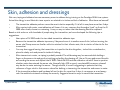
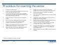
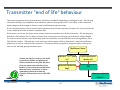
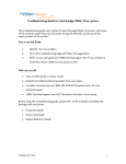
Paradigm REAL time™ insulin pump &
continuous glucose monitoring system.
Troubleshooting Guide.
A practical guide for health professionals working with the Paradigm
REAL Time Insulin pump and Continuous Glucose Monitoring System.
Jill Milliken RN CDE
© J.Milliken RN CDE
2006
1
Table of Contents
1.
2.
Overview of the Paradigm REAL Time components
Troubleshooting
a) Sensor
b) Skin and Taping
3
4
© J.Milliken RN CDE
Daily Self Management Education
Data Management
2006
2
Overview of Paradigm REAL Time™ System
Sen-Serter
Transmitter
Sensor
Communication ICONS
Sensor is on but not
communicating
Antenna Icon, sensor is ON and
transmitting.
Pump
The sensor and the infusion set
should be no less than 2 inches apart.
© J.Milliken RN CDE
2006
3
Troubleshooting Basics
Troubleshooting the Paradigm REAL time system can be time consuming for the patient and their provider if a basic
level of understanding has not been achieved during the training on the system. This guide will help you understand
and incorporate solutions to the most common issues related to this new technology.
Main technical issues include:
•
Sensor to meter glucose comparison
•
Sensor Calibration
•
Error alarms
•
Communication interruption
•
Adhesive and skin issues
•
Software and downloading.
Tools for Troubleshooting:
All of the sensor troubleshooting needed can be done using
information from the following three sources!
-Test Plug
-Screen Icons
-Input Signal (ISIG measured in nA)
*This guide is meant to augment the existing User Guides for the Paradigm REAL Time and Transmitter.
Look for this symbol for quick
tips or other information.
© J.Milliken RN CDE
2006
4
Tips for “Top Ten” Technical Troubleshooting
•Frequent “Bad Sensor” Alarms in first 12 hours
•Sensor was put in the body cold. Leave out of fridge overnight.
Normal to some point. Re-calibrate and wait. If continues, may be
related to end of transmitter life.
•Lost sensor during initialization.
•No Transmitter ID entered or entered wrong. Connections not
“clicked” in place.
•No antenna icon after sensor insertion.
•No ISIG: only “----” in sensor status
•Forgot to go to “start new sensor” and press ACT.
•Sensor not fully connected to transmitter on both sides (two
clicks) no transmitter ID, have not started sensor or dead sensor.
•Weak Signal / Lost sensor
•Transmitter and pump not in close enough proximity. Reapproximate and wait.
•Calibration Error
•A calibration was entered that is outside of the acceptable range
of the current algorithm. May be caused by:
•
•
•
Sensor end.
Great discrepancy between entered meter value and sensed
value.
Low sensor ISIG
Often the solution to the problem is
overlooked due to it’s simplicity.. Trial
and error and patience can help!
© J.Milliken RN CDE
2006
5
Sensor vs Meter BG Troubleshooting
Discrepancy between sensor and meter BG. Possible causes:
•
New sensor: has to settle in to tissue, requires 3 calibrations within first 6 hours.
•
Sensor placed late in the day/evening and not calibrated till morning.
•
Meter variance.
•
Rapidly rising blood glucose. “Sensor Lag” between fluid compartments.
•
Unrealistic expectations.
Reinforce to patient that there will always be a difference between interstitial glucose and blood
glucose. Sometimes it helps to explain what is actually happening when a value is provided. The sensor is
a “relative scale” of blood glucose. The sensor “reads” in electrical values, the blood in mmol/L. When a
calibration is entered, the electrical signal (also known as an Input Signal ISIG) is referenced or
“stamped” to that blood glucose entry. Then as the ISIG rises or falls, the sensor provides a value based
on this “relative scale.” ie) 100na sensor ISIG, a blood glucose is entered as a calibration at 5.2mmol/L.
The algorithm calculates and accepts this “pairing”. When a few minutes later, the ISIG has risen to
119 na the sensor will read something like 5.7mmol/L or conversely, the ISIG drops to 75 na, the value
read off the pump will be more in the range of 4.6mmol/L as an example.
Because it takes time for the body’s fluids to equalize during a rapid fluctuation, the sensor can be off in comparison
to blood glucose this is called “sensor lag” and is different than the acceptable variance between sensor and blood
glucose.
Many patients appreciate this technical
explanation of what is happening and why
there is a difference in values.
© J.Milliken RN CDE
2006
6
Making sense of BG vs Sensor Descrepancy
With early sensor use comes gradual increasing understanding of the system. Support is
essential during the early days as the patient recognizes differences between meter and
sensor relate to several things:
-Rapid fluctuations cause greater discrepancy in values than stable ones.
-What an acceptable variable is: 2 mmol at the hyperglycemic range is more acceptable than a 2 mmol variance
at the low end of the range. However in each scenario, the system is functioning normally. This is a problem with
diabetes not the system.
-There are some issues that can cause greater issues of meter vs BG discrepancy which relate to the meter.
*As the patient becomes more familiar and comfortable with the system, they will experience greater satisfaction.
This is due to the realization that:
-the trends indicated by the arrows are more important than the “point to point” comparison.
-the alert thresholds can help them identify behaviors which lead to alarms – change the behaviors, control the
excursions and get closer meter to sensor values.
Your approach to helping your
patient manage these issues can
make a difference!
© J.Milliken RN CDE
2006
7
Calibrating
Calibrations are essential for the Paradigm system to function. The quality of the data entered will help determine the
quality of the information being made available to the patient. Best calibration practices include using a reliable
glucose meter and entering a glucose value before breakfast, dinner and bedtime as a calibration. Common pitfalls in
terms of calibration are as follows:
•
Entering the same calibration value twice in a row within a few minutes.
•
Using more than one meter to enter calibrations.
•
Entering too many calibrations over a 24 hour period.
•
“Rounding off” calibration values.
•
Inserting the sensor in too late in the day to enter the recommended three calibrations in the first 6 hours.
•
Entering a calibration during a period of rapid glucose change as indicated by two trend arrows up or down.
Calibrations can be entered manually through the bolus or sensor menus. If using the Bolus Wizard, the pump will ask
whether the entered blood glucose value should be entered as a calibration. Suggest to the patient that they choose
“no” if it is a post meal value or during a time of rapid glucose fluctuation. If using the BD Link meter, the patient should
should be encouraged to turn off the RF communication on the meter so that it does not automatically calibrate the
sensor. Refer to the BD link meter user guide for instructions on this meter function.
More is not better in the case of
calibrations! Too many can
throw off the algorithm that is
being used to calculate sensor
glucose.
© J.Milliken RN CDE
2006
8
Bad Sensor Alarm
When did alarm happen?
At sensor insertion
Were the sensor and
transmitter connected PRIOR
to hitting “new sensor”
Yes
Within the first 12 hours
What are the ISIG s?
ISIG’s < 5, sensor may not be
settled in enough.
Did you get 2 cal error’s
previous to this alarm?
Did you calibrate 1-2 hours after a
meal today? Have you calibrated the
system too much today?
No
Check sensor/transmitter connections.
Make sure the two are connected.
After 12 hours of use
If a Cal error occurs, wait at least 2
hours to calibrate again.
Yes
No
Hit “New Sensor” again
Review optimal
calibration times
Cal error x 2
© J.Milliken RN CDE
2006
9
Sensor has reached
the end of its life.
Insert a new
sensor
Skin, adhesion and dressings
Skin care, taping and adhesion become necessary areas to address during training on the Paradigm REAL time system.
Actual skin allergy is rare. Most skin issue reports are related to irritation and lack of adhesion. What have we learned?
•
The transmitter adhesive pad can cause the most irritation especially if it is left in one place more than 2 days.
•
After contact with water, most adhesives will loosen. It is very common that the edges “peel” up from the IV
3000 after a bath, shower or swimming. It may or may not mean that the dressing has to be replaced.
Based on trial and error with hundreds of people using the transmitter, we have developed the following tips or
suggestions.
•
Use a piece of IV 3000 under the two sided transmitter adhesive tape.
•
Remove the transmitter adhesive tape every 2 days and move it to another area of skin (without moving the
sensor site) Pump users are familiar with site rotation for their infusion sets, this is rotation of the site for the
transmitter.
•
You may also suggest leaving the transmitter un-taped to the skin altogether, tucked into a waistband or,
placed in a baby sock and pinned to inside of clothing.
•
After immersion in water, re-taping is probably needed. The old dressing may be removed while holding a
finger on the sensor site and gently stretching and pulling the dressing off. Use an IV prep pad around the skin
surrounding the sensor and replace the IV 3000. Check the ISIG and the calibration variant if there is question
whether water has entered the sensor site. Unusually high >300 or poorly correlated BG vs sensor values all
may be due to water entering the sensor. Though unusual, it is worth suggesting to patients that they
reference a finger-stick to their sensor value after bathing or immersing the transmitter and sensor in water.
•
If the transmitter adhesive pad has been left on the skin for more than 2 days, it can appear as a red weepy
rash. Use antibiotic ointment and keep the area dry. Suggest alternative ways to secure the transmitter.
© J.Milliken RN CDE
2006
10
Allergy vs sensitivity
“True” allergy to the sensor or other components of the system should be reported to the physician. Sensor allergy is
very rare but is independent of any dressings worn or tried and is directly coming from the sensor insertion site.
Localized swelling and oozing from the sensor site is an indication of a sensor allergy. Asking the patient the following
questions will help you decide what kind of issue it is:
1.
2.
3.
4.
5.
Is this the first time you have used this product? (sensor, IV 3000, transmitter tape)
Is the redness in the shape of the dressing itself?
What are your symptoms? Itchy? Swelling? redness?
Is there any oozing from the sensor site itself? How long has it been in?
How long had your transmitter been taped into one place?
Based on the answers to these questions, you will be able to help determine whether the issue is:
-localized or generalized
-symptomatic or non-symptomatic
-possible allergy or sensitivity to a dressing or product.
-”true” allergy to sensor.
Ask the patient to report any sensor allergy to the 1800 technical support line.
© J.Milliken RN CDE
2006
11
Preparation for Sensor Insertion Checklist
Gather the below supplies and equipment in preparation for sensor insertion.
Paradigm REAL Time Monitor.
Transmitter
Sen-Serter
1, Transmitter adhesive pad
2, Alcohol pads
2, IV 3000 occlusive dressing
1, Sensor
Do not use IV prep pads on the skin
before placing the sensor. Use it after
the sensor is in place to help secure
the IV 3000 or tegaderm dressing.
© J.Milliken RN CDE
2006
• Ensure your BG meter has been calibrated with the
lab and is functioning well.
•Use the same BG meter throughout each 72 hour
sensor.
•Wash your hands
•You may open the sensor package and leave the
sensor on the inner sterile surface.
•Open the outer wrapping of the occlusive dressing.
If Smith & Nephew IV 3000 is not available, Op-site
or Tegaderm can be used.
•You will be placing one IV 3000 horizontally and one
vertically over the sensor.
•Allow the skin to dry well after it has been cleansed
with alcohol..
12
Procedure for inserting the sensor
1.
Fit sensor into Sen-serter.
9)
2.
Load Sen-serter by pushing firmly downwards on the
sensor base until you hear a “click”
Hold the Sen-serter on the skin at the angle
indicated by the “feet” of the Sen-serter (about 45º)
10)
3.
You may lock the Sen-serter by turning the white
button on the top end a quarter turn. This ensures it
will not be released accidentally
Unlock the Sen-serter if locked by turning the
button a quarter turn
11)
Insert the sensor by pushing slowly and firmly on the
white button
4.
Remove first layer of clear tape surrounding the
needle.
12)
Hold sensor in place and remove the Sen-serter by
sliding it laterally along the skin
5.
Remove the clear needle guard from the needle
13)
6.
Choose insertion site, lower abdomen, outer
quadrant of the buttock or upper arm.
Remove the second layer of tape by pulling firmly on
the white tab at the base of the sensor.
14)
7.
Clean the intended area of insertion with an alcohol
swab or isopropyl alcohol in circular motion.
Connect the sensor to the transmitter and make
sure both sides have “clicked” into place.
15)
8.
Allow skin to dry. Stretch skin slightly between the
“feet” of the Sen Serter using your fingers.
Tuck the transmitter into a waist band to prevent
the weight of it pulling out the sensor before you
have it taped down.
16)
Tape the sensor site with IV 3000 or other occlusive
dressing.
* Dispose of needle in a sharps container
© J.Milliken RN CDE
2006
13
Sensor Insertion
The sensor should be left out of the fridge even as long as overnight and sensors are useable at room temperature up
to 5 days. This will help avoid the irritating bad sensor alarms in the first few hours. Sensors are best placed in areas of
fatty tissue, however; many children, teens and adults who use the sensor
are lean. There are a couple suggestions for helping place sensors in those who cant quite pinch an inch.
•
Use the upper outer buttocks, even if there is not much fat there, it seems to be less sensitive to insert a sensor
into than the abdomen.
•
The three ways to insert a sensor are: using the serter stretching the skin between the “feet” of the sen-serter,
manually by pinching and using the serter while pinching. The latter can be tricky to do and takes practice. Don’t
worry if you happen to hit a surface capillary and it bleeds a bit. It may not mean that the sensor is no good under
the skin surface.
Practice makes perfect! The first few sensor insertions are often awkward for the patient. They can press the site too
hard as they try and remove the sen-serter or introducer needle. Encourage them to get the introducer needle out as
quickly as possible just after insertion to minimize the amount of mobility of the needle tip in the tissues. This can lead
to lingering discomfort. For insertions in the back of the body, recommend to the patient that they use a mirror to
guide the insertion of the sensor.
Placement in the outer buttock area will save pump sites.
Inserting the sensor into scar tissue such as commonly
seen on the abdomen of a long term insulin user can yield
unreliable sensor values. Evaluate best sensor sites with
patient.
© J.Milliken RN CDE
2006
14
Sensor Insertion Cont’d
•Choose a site with enough body fat for sensor insertion. As a rule
avoid frequent injection or pump sites or areas of scarred lumpy or
hard tissue.
Needle with
guard on.
•Stretch skin between the “feet” of the Sen-Serter.
“Feet”
•Secure the sensor once inserted with your fingers and slide the SenSerter laterally off the sensor.
•Remove the needle by pulling the “wing” firmly.
•Dispose of the needle in a biohazardous sharps disposal unit.
© J.Milliken RN CDE
2006
15
“Wing”
2nd piece
of tape
Transmitter “end of life” behaviour
The current transmitter has an internal battery which has a variable life depending on the degree of use. The following
information will help you troubleshoot the transmitter when it is nearing the end of it’s use. Note, as the transmitter
battery begins to lose strength it does not cause unreliable sensor glucose values.
A low transmitter battery notice can be found in the sensor status screen only when the sensor is in use. It may take up
to two weeks before the transmitter completely fails.
If the sensor is not in use, the sensor status screen cannot be accessed to provide this information. The test plug may
be used to verify battery life. If it does not “beep” when connected to the test plug, the transmitter is likely finished.
On some occasions however, even with a beep when the transmitter is connected, there is not enough battery life to
fully initialize a sensor. The behaviour in this scenario is that the pump will alarm “bad sensor” within the initialization
phase even as early as 5 minutes after connection. The patient then is prompted to change the sensor and may use
two or more and keep getting the same alarms.
“Bad Sensor” alarm
Canada was the first country in the world
to launch this product and we have the
oldest transmitters in the field. We learn
from your experiences and that of your
patients. If your patient has any questions
about warranty, transmitter or sensor
replacement, please have them call
Canadian Customer Service at 1-800-2844416
© J.Milliken RN CDE
2006
Is this the 2nd or 3rd sensor
Is your transmitter 4+
try?
Months old?
Have you tried the test
Plug?
YES
Report to technical
Support
16
Using Bolus Wizard & real time glucose.
The Bolus Wizard tool becomes more important with the advent of “real time” glucose. Patients must understand how
to self manage using the new information available with the Paradigm REAL time.
Why?
1.
The temptation to correct with every threshold alarm.
2.
Lack of overall understanding of insulin action.
The basics of the Bolus Wizard include the use of:
-Insulin to carbohydrate ratio
-Insulin sensitivity factor
-Target glucose (pre-meal)
-Active insulin curve (2-8hrs default 6hrs)
The Bolus Wizard calculation is done when the glucose is entered into the pump. The calculation is as follows:
Correction insulin (if needed) PLUS any bolus for food needed MINUS active insulin from correction insulin only. (not
food bolus insulin)
Scenario:
Tom takes his glucose after receiving a high threshold alarm at 13.7mmol 2.5 hours after his meal. He enters that value
into the bolus wizard and enters “0” for food. Based on his ratios his pump estimates he needs 3 u to correct but then
subtracts 1. 7 u from the total bolus and suggests a correction bolus amount of 1.3u. At this point, Tom has a choice: he
can “ACT” and deliver the correction or wait until his next meal to correct. Some practitioners will suggest that the
patient NOT correct a mid-meal glucose and instead wait to see where he “lands” however; others will recognize that
“glucose exposure” during this hyperglycemic time can cause complications by virtue of higher A1c over the long term
and as long as the Bolus Wizard is used for the next meal, bolusing again will not cause overlapping insulin (stacking)
© J.Milliken RN CDE
2006
17
Setting Alert Thresholds
Thresholds for hypoglycemia or hyperglycemia alerts can be turned ON or Off, raised and lowered at an increased or
decreased alarm interval (snooze) There are some considerations when setting threshold alarms:
1.
What kind of control does the patient currently have?
•
2.
Most patients are unaware of their overall daily control and may find frequent alarming a nuicance. This is a problem with
diabetes, not the sensor or pump system. Intervention: set the hyperglycemia target high or leave it off altogether for the
first sensor. A suggested initial threshold is 13 or 14 mmol/L.
How do you as the health provider wish the patient to intervene with the alerts?
•
The alerts are only as effective as the decisions or behaviour changes they can prompt. If your patient is having trouble
learning the therapy or is going through a time when evaluation of glucose is not a priority, it may be best to leave the
alerts off. The information can be downloaded and observed retrospectively with the care provider.
In the case of pediatrics, the parent may choose to leave these alarms off during the school day so that there is no
confusion on what is to be done about them. Scrolling back through the day’s values can be sufficient in some children.
•
3.
Does the patient have hypoglycemia unawareness or a history of lack of hypo symptoms?
•
•
In the case of severe hypoglycemia or lack of hypo symptoms, the low threshold may be set a little higher than the
recommended 4.5mmol/L in order to increase the chances of capturing a low glucose. The higher the low threshold alert is
set however, the more frequent the “false alarms” to the patient. For example, if the low threshold is set at 5.0mmol, any
sensor glucose up to 7 mmol is still an acceptable reading. The frequent alarming within the normal range may cause the
“boy that cried wolf” phenomenon – ignoring the alarms.
The trade off of more frequent alarming may still be acceptable to the patient with hypo unawareness. Discussion of the
alert threshold with the health provider is warranted.
Alert thresholds should be considered
dynamic! The longer on the sensor,
the tighter the thresholds can be set.
© J.Milliken RN CDE
2006
18
Follow up and support
Several key areas should be addressed at the first subsequent visit after the first sensor use. Some areas for discussion
include:
•
General activities of daily life and sensor wear: sports, sleeping, clothing, questions from other people, ability to
hear the alarm during work or overnight.
•
Any skin issues? Local discomfort? Tape not sticking? Rotating transmitter adhesion area, hair, itchy?
•
Calibrations: are they well correlated? What is the difference they noticed? If more than 2mmo was that during a
rapid rise in BG? Did they calibrate pre-meal and bedtime? General observations about calibration.
•
Alarms: If the alert thresholds were being used, were they effective at notifying the patient for events? Were they
aware of any event before the alarm went off or did the alarm warn them? Are the alarms keeping them up? Do
they need to be adjusted? Is the snooze interval effective?
•
Errors: Were there any error alarms? Did they verify the ISIG? Troubleshoot? Re-start sensor? Call the tech support
line?
•
Glucose awareness: Did you view any trend arrows? Did you intervene? What did you do? Verify by finger-stick?
(Reinforce diabetes “basics” treating lows and highs. ) Did you identify any trends which you were not aware of?
Your patient will need help learning how to use
this new information. Many people are unaware
of their daily glucose variations.
© J.Milliken RN CDE
2006
19
Using Data Management
There are exciting options for viewing sensor glucose and other parameters using either Solutions pumps and meters
software or CareLink web-based software. Patients can access either system with the following components:
•
Internet access – high speed is best.
•
Paradigm REAL Time pump
•
Com Link or BD Link Meter and cable. For radio frequency (“RF” interface)
There are some common issues which patients can encounter when downloading their data which can interfere in the
completion of the data transfer. These include:
- interference caused by other radio frequency devices such as optical mice, and the computer itself. Stretch the
cable away from the computer and place the pump right beside the RF interface.
-dial up connection can cause a delay in the data transfer and the server “hangs up” on the download.
-There is no communication between the pump and the software usually caused by not having the proper Serial
numbers of the pump and or the link meter entered into the system.
-There is activity going on with the pump at the time: a bolus, a temp basal, low battery, etc.
In rare cases, there is a problem located within the pump software which causes a problem with communication to the
software. Ask your patient to call the tech support number on the back of the pump after exhausting all options.
The current software version for Solutions
pumps and meters is 7.0c. The CareLink
website is http://carelink.minimed.com
© J.Milliken RN CDE
2006
20