1
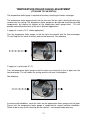
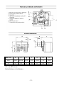
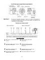
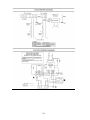
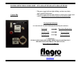
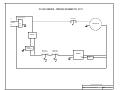
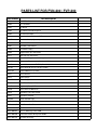
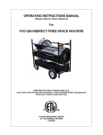
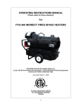
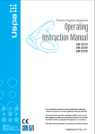
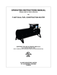
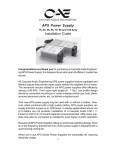
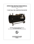
OPERATING INSTRUCTIONS MANUAL
(Please retain for future reference)
For
FVN/P-200 INDIRECT FIRED SPACE HEATERS
CERTIFIED FOR USE IN CANADA AND U.S.A.
As per Standard ANSI Z83.7/CSA 2.14 2000 Gas Fired Construction Heaters / Unattended Type.
FLAGRO INDUSTRIES LIMITED
ST. CATHARINES, ONTARIO
CANADA
GENERAL HAZARD WARNING:
FAILURE TO COMPLY WITH THE PRECAUTIONS AND INSTRUCTIONS PROVIDED
WITH THIS HEATER, CAN RESULT IN DEATH, SERIOUS BODILY INJURY AND
PROPERTY LOSS OR DAMAGE FROM HAZARDS OF FIRE, EXPLOSION, BURN,
ASPHYXIATION, CARBON MONOXIDE POISONING, AND/OR ELECTRICAL
SHOCK.
ONLY PERSONS WHO CAN UNDERSTAND AND FOLLOW THE INSTRUCTIONS
SHOULD USE OR SERVICE THIS HEATER.
IF YOU NEED ASSISTANCE OR HEATER INFORMATION SUCH AS AN
INSTRUCTIONS MANUAL, LABELS, ETC. CONTACT THE MANUFACTURER.
WARNING:
FIRE, BURN, INHALATION, AND EXPLOSION HAZARD.
KEEP SOLID
COMBUSTIBLES, SUCH AS BUILDING MATERIALS, PAPER OR CARDBOARD, A
SAFE DISTANCE AWAY FROM THE HEATER AS RECOMMENDED BY THE
INSTRUCTIONS. NEVER USE THE HEATER IN SPACES WHICH DO OR MAY
CONTAIN VOLATILE OR AIRBORNE COMBUSTIBLES, OR PRODUCTS SUCH AS
GASOLINE, SOLVENTS, PAINT THINNER, DUST PARTICLES OR UNKNOWN
CHEMICALS.
WARNING:
NOT FOR HOME OR RECREATIONAL VEHICLE USE.
WARNING:
INTENDED USE IS PRIMARILY THE TEMPORARY HEATING OF BUILDINGS
UNDER CONSTRUCTION, ALTERATION, REPAIR OR EMERGENCIES ONLY.
ALWAYS PROVIDE ADEQUATE VENTILATION. 1 SQ. IN. OF FRESH AIR MUST
BE SUPPLIED FOR EVERY 1000 BTUH OF HEAT.
THIS HEATER SHALL BE INSTALLED SUCH THAT IT IS NOT DIRECTLY
EXPOSED TO WATER SPRAY, AND/OR DRIPPING WATER.
-2-
This heater is designed and approved for use as a
construction heater under Standard ANSI Z83.7/
CGA 2.14. 2000.
We cannot anticipate every use which may be made
of our heaters. CHECK WITH YOU LOCAL FIRE
SAFETY AUTHORITY IF YOU HAVE QUESTIONS
ABOUT APPLICATIONS.
Other standards govern the use of fuel gases and heat
producing products in specific applications. Your local
authority can advise you about these.
SPECIFICATIONS
Model …………………………………………………….….
FVP-200 Propane
FVN-200 Natural Gas
Input …………………………………………………….…...
200,000 btuh
Fuel ………………………………………………………….
FVP-200 Propane
FVN-200 Natural Gas
Manifold Pressure ………………………………………….
3.5” W.C. Propane
3.5” W.C. NG
Maximum Inlet Pressure …………………………………
13.0” W.C. Propane
10.0” W.C. NG
Ignition ………………………………………………………
Direct Spark Ignition
…….……………………………………………...…
Thermostat Control
Air Circulation ……………………………………………….
1500 cfm
Fuel Consumption ……………………………………….....
9.25 lbs/hr Propane
190 cfh NG
Approved ………………………………………………….....
cETLus listed
Weight ………………………………………………….....
280 lbs
-3-
INSTALLATION:
The installation of this heater for use with natural gas shall conform with local codes or, in the
absence of codes, with the National Fuel Gas Code ANSI Z223.1/NFPA 54 and the Natural
Gas and Propane Installation Code, CSA B149.1-00. This heater must be installed by a
qualified gas technician, following local codes published by the authority having jurisdiction.
All installations performed in the state of Massachusetts must be completed by a qualified
plumber and gas fitter of the State of Massachusetts.
The installation of this heater for use with propane tank or cylinder shall conform with Local
codes or, in the absence of local codes, with the Standard for the Storage and Handling of
Liquefied Petroleum Gases, ANSI/NFPA 58 and the Natural Gas and Propane Installation
Code, CSA B149.
This heater must be located at least 10ft (3m) from any propane gas cylinder. This heater
shall not be directed toward any propane gas container within 20ft (6m).
CONNECTING THE CYLINDER:
If cylinders are used to supply the heater, no cylinders smaller than 100lb capacity shall be
used. These cylinders must supply a vapor withdrawal only.
1.
All cylinder connections must be made using a wrench to tighten the POL fitting.
2.
Be sure that the cylinder valve is in the closed position when connection or
disconnecting the cylinder.
3.
A soap and water solution must be applied to all connections in order to leak check
the system.
The gas must be turned off at the propane supply cylinder(s) when the heater is not in use.
When the heater is to be stored indoors, the connection between the propane supply
cylinder(s) and the heater must be disconnected and the cylinders removed from the heater
and stored in accordance with Standard for the Storage and Handling or Liquefied Petroleum
Gases, ANSI/NFPA 58 and CSA B149.1, Natural Gas and Propane Installation Code.
PIPING:
This heater must be installed by a qualified gas technician following local codes
published by the authority having jurisdiction. Sizing of supply piping must be
determined using the length of pipe run as well as total btuh rating of the
appliance(s). Appropriate piping tables must be used to determine size of
supply piping dependant on the length of run from source.
-4-
PRESSURES:
MAXIMUM INLET PRESSURES:
LP:
NG:
13.0 IN. WC.
10.0 IN. WC.
MINIMUM INLET PRESSURES:
LP:
NG:
8.0 IN. WC.
7.0 IN. WC.
This heater must be supplied by pressures indicated on the approval
label. Over pressure may cause controls to fail.
DO NOT supply this unit with more than ½ psig (14.0 in. W.C.)
Note: A second stage regulator must be installed if the supply pressure
exceeds ½ psig.
FUEL:
This heater will operate on propane OR natural gas – NOT BOTH. The
manifold pressures are listed on the approval label. To determine which
fuel to use see rating plate. DO NOT attempt to use the heater without
consulting the rating plate.
Note: The proper main burner orifice must be installed and rating plate
must reflect the fuel the heater burning. DO NOT operate the heater
with out consulting the rating plate.
Heater conversion must be done by a qualified technician and rating
plate must reflect any change.
HOSES:
ELECTRICAL:
All hoses used to connect this heater of fuel supply must be Type 1
approved propane / natural gas hose assemblies.
WARNING
Electrical Grounding Instructions
This appliance is equipped with a three-prong (grounding) plug for your
protection against shock hazard and should be plugged directly into a
properly grounded three-prong receptacle.
115v supply must be available. Please note that the heater requires 15
amps for proper operation. Ensure appropriate gauge extension cord is
used.
• 12/3 AWG at 50 Feet
• 10/3 AWG at 100 Feet
-5-
FV SERIES CONSTRUCTION HEATER – VENTING REQUIREMENTS
1. VERTICAL FLUE TERMINATIONS
B
A
VERTICAL FLUE RUN
D
HORIZONTAL FLUE RUN - RISE RATIO 1:10
FLUE OUTLET OF HEATER
2. HORIZONTAL FLUE TERMINATIONS
B
C
FLUE OUTLET OF HEATER
EXTERIOR WALL
A -
VENT TERMINATION MUST BE A MINIMUM OF 2FT HIGHER THAN ANY POINT
WITHIN 10FT.
B -
MAXIMUM HORIZONTAL RUN IS 30FT.
NOTE: 90deg ELBOW = 10ft HORIZONTAL VENT ALLOWANCE
45deg ELBOW = 5ft HORIZONTAL VENT ALLOWANCE
C -
VENT TERMINATION IN HORIZONTAL POSITION MUST BE MINIMUM 4ft FROM ANY
COMBUSTABLE SURFACE
D -
EXTERIOR VERTICAL VENT TERMINATION MUST BE A MINIMUM OF 2ft.
NOTE:
ALL VENT TERMINATIONS MUST HAVE A RAIN CAP INSTALLED AS PER
LOCAL CODE REQUIREMENTS.
-6-
CLEARANCE TO COMBUSTIBLES:
Model FVN/P-200
TOP
FRONT
SIDES
REAR
FLUE PIPE
3 ft
10 ft
1 ft
2 ft
3 ft
MAINTENANCE:
1. Every construction heater should be inspected before each use, and at least
annually by a qualified service person. Incorrect maintenance my result in
improper operation of the heater and serious injury could occur.
2. The hose assemblies shall be visually inspected prior to each use of the heater. If it is
evident there is excessive abrasion or wear, or the hose is cut, it must be replaced prior to
the heater being put into operation. The replacement hose assembly shall be that
specified by the manufacturer.
3. The appliance must be kept clear and free from combustible materials, gasoline and other
flammable vapors and liquids.
4. The flow of combustion and ventilation air must not be obstructed. Be sure to check the
fan assembly and ensure that the motor and blade are operating properly.
5. Compressed air should be used to keep components free of dust and dirt build up. Note:
Do not use the compressed air inside any piping or regulator components.
6. Fan Limit Switch (Part# FV-407A) should be replaced if the fan motor does not shut off
after the heat exchanger has cooled down.
7. High Limit Switches (Part# FV-206 & FV-437) should be checked each season. These
limit switches will ensure the burner shuts down if the temperature exceeds 250°F at the
outlet.
8. Heat Exchanger should be cleaned if smokey conditions continue even after the air
adjustments on the burner are made.
-7-
START UP INSTRUCTIONS:
1.
Be sure the switch is in the “OFF” position.
2.
Ensure electrical cord is grounded and heater is on a level surface.
3.
Plug in supply cord to 115v, 15amp outlet.
4.
Make sure Smart Indicator Light is green, if not green, please refer to the “Power
Supply Indicator Label” before proceeding with start up.
5.
Move switch to “MANUAL” position for manual control.
6.
Move switch to “THERMOSTAT” position for thermostatic control.
Please Note:
1. If using Thermostat on unit, unit must be started in Thermostat position.
2. When changing between manual and thermostat operation, the heater must be left in
the “OFF” position for 30 seconds to prevent the burner from locking out.
3. When using a generator for electrical supply, make sure the generator is properly
grounded and generator is at a 60Hz frequency.
4. In the event that a generator is being used and the generator runs out of fuel, make
sure the heater switch is in the “OFF” position before restarting generator, failure to do
so may damage heater.
TO SHUT DOWN:
1.
Close main gas supply valve while heater is operating.
2.
Move switch to “OFF” position.
3.
Disconnect heater from gas supply.
NOTE:
Fan will continue to operate after the burner shuts down. Once the unit cools
down, the fan will stop.
-8-
IF HEATER FAILS TO START:
1.
Press manual reset button at rear of burner.
2.
Check gas pressure supply. Supply and manifold pressure must follow those on
rating plate.
3.
Ensure proper power supply and extension cord is being used.
4.
If heater fails to ignite after 3 attempts, call your supplier for service.
SAFE OPERATION PRECAUTIONS:
1.
For use with propane or natural gas only. See approval label.
2.
Use switch to shut down the heater.
unplugging the electrical cord.
3.
Do not plug anything other that the thermostat into the “Thermostat” plug.
4.
Follow electrical requirements shown on rating plate and/or Electrical requirements
section of this manual.
5.
Before removing any guards or performing any maintenance, be sure that the main
power supply is disconnected.
-9-
Do not try to shut down the heater by
COMBUSTION AIR ADJUSTMENTS:
NOTE:
Proper combustion air adjustment must be achieved using a certified
combustion analyzer to ensure complete combustion.
The air adjustment should be made to achieve 10% CO2 on natural gas and
12% CO2 on propane.
SETTING THE AIR ADJUSTMENT PLATE
A) Regulation of the combustion air flow is made by adjustment of the manual AIR
ADJUSTMENT PLATE (1) after loosening the FIXING SCREWS (2 and 3). The initial
setting of the air adjustment plate should be made according to Column 5 in the Burner
Set-up Chart.
B) The proper number on the manual AIR
ADJUSTMENT PLATE (1) should line up
SETTING INDICATOR (4) on the fan
cover. Once set, the air adjustment plate
secured in place by tightening SCREWS 2
with
the
housing
should be
and 3.
C) The final position of the air adjustment
vary on each installation. Use instruments
establish the proper settings for maximum
plate
will
to
CO2.
NOTE: Variations in flue gas, CO2 and
temperature readings may be experienced
when the
burner cover is put in place. Therefore, the burner cover must be in place when making
the final combustion instrument readings, to ensure proper test results.
BURNER SET-UP CHART
1
2
3
4
5
FIRING RATE
(BTUH)
ORIFICE-LP
ORIFICE-NG
HEAD
SETTING
AIR DAMPER
SETTING
200,000
PART #
FVP-225
PART #
FVN-226
5
3 LP
3.8 NG
- 10 -
TEMPERATURE FEELER GAUGE ADJUSTMENT
(ATTACHED TO FAN SWITCH)
The temperature feeler gauge is required to be always touching the heater exchanger.
The temperature feeler gauge controls the air flow over the fan switch, which eliminates any
unnecessary fan cycling. The temperature feeler gauge can be adjusted for different outside
temperatures, by rotating the location of the temperature feeler gauge holes. This will
provide maximum performance of the unit in different applications.
If supply air is warm (-5° C, indoor application):
Turn the temperature feeler gauge so that the holes are parallel with the heat exchanger.
This will help the fan switch to remain cool and not overheat. See following:
If supply air is cold (under -5° C):
Turn the temperature feeler gauge so that the holes are closed off as the air goes over the
heat exchanger. This will reduce fan cycling and the unit from shutting down.
See following:
In extreme cold conditions, cover the holes on the temperature feeler gauge using foil tape.
Ensure that the temperature feeler gauge is readjusted for warmer weather conditions.
Failure to do so may result in burning out fan switches – not covered under warranty.
- 11 -
Model 200
A
B
C
F
G
*G1
H
Inches
9 3/16
10 11/16
6 11/16
11 5/8
3 15/16
10
3 9/16
mm
233
272
35
295
85
255
91
*G1 is for LBT version
Gasket thickness is 4 millimeters
- 12 -
ELECTRODE AND FLAME PROBE ADJUSTMENTS
IMPORTANT:
Do not turn the ignition electrode. Leave it as shown in the drawing. If
the ignition electrode is put near the ionization probe, the amplifier of the
control box may be damaged.
TYPICAL GAS TRAIN LAYOUT
FIELD SUPPLIED
RIELLO SUPPLIED
GAS TRAIN LEGEND
GAS SUPPLY & FLOW DIRECTION
OF GAS
GAS APPLIANCE PRESSURE
REGULATOR
AS SUPPLY MAIN SHUTOFF MANUAL
VALVE (FIELD SUPPLIED
SAFETY SHUTOFF GAS VALVE
(VS) 24V OR 120V SUPPLIED)
OPERATED
GAS SUPPLY PRESSURE TEST
POINT (FIELD SUPPLIED)
MAIN GAS VALVE (V1) 24V OR 120V
OPERATED SINGLE STAGE
GAS TRAIN PIPE DIAMETER SIZE(S):
BURNER G200 1/2" NPT
GAS BURNER MANIFOLD TEST POINT
- 13 -
- 14 -
POWER SUPPLY INDICATOR LIGHT - FVO-400 & FVNP-400 & FVO-200 & FVNP-200
Control Box
* The power supply indicator light will help you detect any faulty
power supplied to the heater.
* The power supply indicator light will detect various power supply issues
such as; gounding issues or reverse Polarity or missing connections
Warning Light Indications
The smart indicator can detect and display the following fault conditions:
Green Light
Meets Power Requirements
Solid Red Light
Reverse Polarity
Flashing Red Light
Ground or Neutral issue
** ATTENTION**
IF RED LIGHT IS INDICATED, MAKE CORRECTIONS TO POWER SUPPLY
BEFORE TURNING HEATER ON. FAILURE TO DO SO.
WILL VOID ANY WARRANTY
www.flagro.on.ca
FV-200 SERIES - WIRING SCHEMATIC 2011
POWER INDICATOR
FAN SWITCH
L1
T1
115 VAC
FAN MOTOR
T3
N
T4
G
G
SWITCH
REMOTE
THERMOSTAT
G
REAR HIGH
LIMIT SWITCH
FRONT HIGH
LIMIT SWITCH
BURNER
X
RED
LIGHT
G
FLAGRO INDUSTRIES LIMITED
TITLE:
FV-200 - WIRING SCHEMATIC
DWG. NO. FV-200 WS 2011
PARTS LIST FOR FVN-200 / FVP-200
Part Number
Part Description
FV-201
1/2 HP Fan Motor
FV-202
15” Fan Blade
FV-203
12” Wheel
FV-204
12” Power Cord c/w Plug End
FV-205
SS Heat Exchanger
FV-406
High Limit Switch (Outlet) 250F
FV-407A
Fan Limit Switch (Adjustable)
FV-407G
Fan Limit Silicone Gasket
FV-207
Lockable Caster Wheel
FV-208
Fan Motor Canopy
FV-409
Toggle Switch (on control box)
FV-411
Red Light (on control box)
FV-214
Thermostat Plug (on control box) prior to 2011
FV-414B
Thermostat Plug (on control box) as of 2011
FV-215
Female Connector for FV-TH2 (Prior 2011)
FV-415B
Male Connector for FV-THB (As of 2011)
FVNP-224
Riello G200 Burner (LP/NG)
FV-231
Burner Gasket
FV-433
Feeler Gauge
FV-433B
Feeler Gauge-Solid
FV-234
Front Face Plate (1 x 12”)
FV-437
High Limit (Rear) 150F
FV-240
Wheel Axle FV-200 Series
FV-446
Sight Glass c/w Fiber Gasket
FV-447
Sight Glass Washer
FV-449SI
Smart Indicator Light
FVNP-300162
Ignition Module (LP/NG)
FVNP-3002307
G200 Burner Sub-Base
FVNP-3005447
Gas Pressure Test Point Adapter
FVNP-3006687
Chassis Mounting Collar G200
FVNP-3006899
Distributor Head & Mixing Plate G200
FVNP-3007274
Electrode Assembly
FVNP-3007310
Ionization Lead
FVNP-3020206
Flame Rod Assembly
FVNP-3007448
Ground Lead & Connector for G200 Burner
ACCESSORIES
FV-HD12
12” X 12ft HiTex Vinyl Ducting
FV-THA
Thermostat c/w 25FT Cord – prior to 2011
FV-THB
Thermostat c/w 25 FT Cord – as of 2011
FVN-227
LP to NG Conversion Kit
FVP-228
NG to LP Conversion Kit
FV-VK
6” x 3FT C-Vent c/w Rain Cap