1
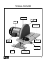
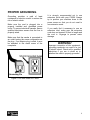
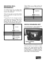
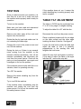
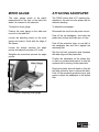
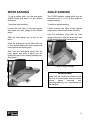
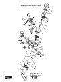
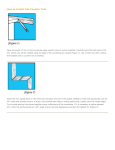
CX506 12" DISC SANDER User Manual (March 24th, 2014) TABLE OF CONTENTS General Safety Instructions..................................................................................... 3 Specific Safety Instructions..................................................................................... 4 CX506 Features...................................................................................................... 5 Physical Features ................................................................................................... 6 Unpacking ............................................................................................................... 7 Workbench Load..................................................................................................... 7 Clean Up................................................................................................................. 7 Proper Grounding ................................................................................................... 8 Mounting On A Workbench..................................................................................... 9 Switch Disabling Key .............................................................................................. 9 Test Run ................................................................................................................. 10 Table Tilt Adjustment .............................................................................................. 10 Miter Gauge ............................................................................................................ 11 Attaching Sandpaper ..............................................................................................11 Miter Sanding.......................................................................................................... 12 Angle Sanding ........................................................................................................ 12 Maintenance ........................................................................................................... 13 Cleaning.................................................................................................................. 13 Parts Diagram ......................................................................................................... 14 Parts List................................................................................................................. 15 Warranty ................................................................................................................. 16 2 GENERAL SAFETY INSTRUCTIONS FOR MACHINES Extreme caution should be used when operating all power tools. Know your power tool, be familiar with its operation, read through the user manual and practice safe usage procedures at all times. ALWAYS read and understand the user manual before operating the machine. CONNECT your machine ONLY to the matched and specific power source. ALWAYS wear safety glasses respirators, hearing protection and safety shoes, when operating your machine. DO NOT wear loose clothing or jewelry when operating your machine. A SAFE ENVIRONMENT is important. Keep the area free of dust, dirt and other debris in the immediate vicinity of your machine. BE ALERT! DO NOT use prescription or other drugs that may affect your ability or judgment to safely use your machine. DISCONNECT the power source when changing drill bits, hollow chisels, router bits, shaper heads, blades, knives or making other adjustments or repairs. NEVER leave a tool unattended while it is in operation. NEVER reach over the table when the tool is in operation. ALWAYS keep blades, knives and bits sharpened and properly aligned. ALL OPERATIONS MUST BE performed with the guards in place to ensure safety. ALWAYS use push sticks and feather boards to safely feed your work through the machine and clamp the work-piece (when necessary) to prevent the workpiece from any unexpected movement. ALWAYS make sure that any tools used for adjustments are removed before operating the machine. ALWAYS keep the bystanders safely away while the machine is in operation. NEVER attempt to remove jammed cutoff pieces until the saw blade has come to a full stop. 3 CX506 – 12" DISC SANDER SPECIFIC SAFETY INSTRUCTIONS Read and follow all the instructions and safety precautions in the user manual before setup or use. Make sure before making any adjustments, the switch is in the “OFF” position and the cord is un-plugged. For the protection of your eyes, always wear safety glasses, goggles or face shield while operating the sander. Never leave the sander unattended while it is running. Never touch the moving sanding disc. Keep your hands and fingers away from the moving sanding disc. If the work-piece is small or difficult to hold, use work-piece holding fixture. Always support the work-piece on the work table against the rotation direction of the sanding disc. All guards must be in place while operating the sander to avoid any injuries. Always feed the stock smoothly against the rotation of the sanding disc. Do not use excessive force while operation. Always sand work-pieces which are stable and if you have any doubt about the stability of the material, do not sand it. Do not use the sanding discs that are damaged or if the adhesive is not sticking firmly. If the sanding disc comes off during operation, it might cause damage to the work-piece or injury to the operators fingers. Make sure to position the work table in a position where the gap between the sanding disc and the table does not exceed 3mm. Do not wear loose clothing, neckties, jewelry or gloves that can get caught in moving parts. Confine long hair and keep sleeves above the elbow. Make sure you have read and understood all the safety instructions in the manual and you are familiar with your sander, before operating it. If you fail to do so, serious injury could occur. WARNING! The safety instructions given above can not be complete because the environment in every shop is different. Always consider safety first as it applies to your individual working conditions. 4 CX506 – 12" DISC SANDER FEATURES MODEL CX506 – 12" DISC SANDER As part of the growing line of Craftex CX-Series woodworking equipment, we are proud to offer the CX506 a 12" Disc Sander. By following the instructions and procedures laid out in this user manual, you will receive years of excellent service and satisfaction. The CX506 is a professional tool and like all power tools, proper care and safety procedures should be adhered to. Motor............................................ 1.2-HP, 120-V, 60-Hz, 8.0 Amps, Single Phase Disc Speed .................................. 1750 RPM Power Switch ............................... ON/OFF with Removable Locking Key Disc Diameter .............................. 12" Table Size.................................... 16-3/8" x 6-7/8" Table Tilt ...................................... 0 - 45° Table Height ................................ 7" Dust Port Size .............................. 2" Miter Gauge ................................. Yes Gross Weight ............................... 63 lbs Warranty ...................................... 3 Years 5 PHYSICAL FEATURES Disc Guard 12" Sanding Disc Motor Work Table ON/OFF Switch Miter Slot Miter Gauge Base Tilt Scale with Lock Knob 6 UNPACKING CLEAN UP The machine is properly packaged and shipped in a carton for safe transportation. When unpacking, carefully inspect the carton and ensure that it has not been damaged during transit. Open the carton and check that the machine and the parts are in good condition. The unpainted surfaces of the machine are coated with a rust preventive waxy oil to prevent corrosion during shipment and storage. You will need to clean up this oil before operating the machine. DESCRIPTION Put some cleaner or degreaser on the unpainted areas where rust preventive oil is and leave it for 5 minutes. QTY Sander.......................................... 1 pc 12" Sanding Disc.......................... 1 pc Miter Gauge ................................. 1 pc User Manual................................. 1 pc Use a rag and wipe off the oil. If the oil does not wipe off, repeat the above steps 2 to 3 times. Once the unpainted surfaces are clean, use metal protectant to prevent from rust. NOTE: While doing inventory, if you can not find any part, check if the part has already been installed on the machine. Some parts come pre-assembled for shipping purposes. WORKBENCH LOAD CX506 sander is not very heavy. If using a workbench, make sure to place the sander on a workbench that has the capacity to support the weight of the CX506 sander. 7 PROPER GROUNDING Grounding provides a path of least resistance for electric current to reduce the risk of electric shock. Make sure the cord is plugged into a properly installed and grounded power outlet. To prevent electrical hazards, have a qualified electrician ensure that the line is properly wired. Make sure that the sander is connected to an outlet having the same configuration as the plug. If an adaptor plug is used, it must be attached to the metal screw of the receptacle. It is strongly recommended not to use extension cords with your CX506. Always try to position your machine close to the power source so that you do not need to use extension cords. If you really find it necessary to use an extension cord, make sure the extension cord does not exceed 50-feet in length and the cord is 14-gauge to prevent motor damage. WARNING! Improper connection of the equipmentgrounding conductor can result in a risk of electric shock. Check with a qualified electrician if you are in doubt as to whether the outlet is properly grounded. Figure-1 120-volts outlet for CX506 8 MOUNTING ON A WORKBENCH "Direct Mount" is to simply secure the sander to the workbench using lag screws. See figure-3. The CX506 features four pre-drilled holes on its base which allow mounting the sander to the workbench. There are two ways to mount the sander onto the workbench; through mount and direct mount. "Through Mount" is the strongest mounting option where the holes are drilled all the way through the workbench. Hex bolts, washers and hex nuts are used to secure the sander to the workbench. See figure-2. Figure-3 Direct Mount SWITCH DISABLING KEY The CX506 features a switch disabling key which prevents from unauthorized use. Figure-2 Through Mount Figure-4 Switch disabling key removed When the machine is not used for a longer period of time, simply remove the switch disabling key and the ON/OFF switch will not work without it. To enable the switch, insert the key back to its place and you will then be able to turn ON the machine. 9 TEST RUN Once you have mounted your machine, it is then time for a test run to make sure that the machine works properly and is ready for operation. To test run the machine: Make sure you have read and understood the instructions given in the manual. Remove and clear away all the tools and objects from the machine. Rotate the disc by hand and make sure it is not contacting the table edge. Connect the cord to the power source and turn ON the machine. During the test run if there is any unusual noise coming from the machine or the machine vibrates excessively, shut off the machine immediately and disconnect the cord from the power source. Check all the parts you have assembled, once again and investigate to find out the problem. If the machine does not run, it means the switch disabling key is working properly and test is complete. TABLE TILT ADJUSTMENT The table on CX506 can be positioned from 0° to 45° at any angle, for angled sanding. To adjust the table tilt to 90° with the disc: Disconnect the cord from the power source. Place a machinist square with its one edge on the table surface and the other edge touching the face of the disc. See figure-9. Loosen the lock levers under the table and adjust the table so that it is perfectly perpendicular to the sanding disc and retighten the lock levers. Adjust the stop bolt and tighten in position. If you want to adjust the table to an angle less than 90°, remove the stop bolt. If the machine runs smoothly with little or no vibration, then it is operating correctly. Turn OFF the sander. Remove the switch disabling key from the ON/OFF switch. Try to turn ON the machine. If the machine starts, immediately stop the machine and unplug the cord from the power source. Do not run the machine until this safety feature is fixed. Figure-5 Table tilt 10 MITER GAUGE ATTACHING SANDPAPER The miter gauge needs to be adjust perpendicular to the face of the table slot when it is mounted to the table slot. The CX506 comes with a 12" sanding disc, attached to the cast iron disc platen with its adhesive backing. To adjust he miter gauge: To attach the sandpaper: Position the miter gauge on the table and mount it to the table slot. Disconnect the cord from the power source. Loosen the adjusting screw on the miter gauge and make it flush with the edge of the square. Loosen the screws securing the angle pointer and adjust the pointer to 0° mark. Retighten the screw that secures the angle pointer. Peal off the old sandpaper, and clean the platen disc surface and make sure it is dry. Peel off the protective layer on one-half of the sandpaper disc and fold it against the remaining half. Slip the half with protective layer between the table edge and the platen disc. Position the sandpaper on the platen disc so that it is centered and press it so that the exposed half is sticking on the platen disc. Rotate the platen disc with hand so that the half with protective layer is above the table. Peel off the remaining protective layer and press to attach the sandpaper to the platen disc. Figure-6 Adjusting miter gauge 11 MITER SANDING ANGLE SANDING To get a perfect miter, cut the work-piece slightly longer and sand it to the desired dimension. The CX506 features a table which can be positioned from 0° to 45° at any angle for angled sanding. To perform miter sanding: To perform angled sanding: Loosen the lock knob on the miter gauge and adjust the miter gauge to the desired angle. Loosen position the table at the desired angle shown on the scale under the table. Slide the miter gauge into its slot on the table. Hold the work-piece firmly with the miter gauge and push it into the down-spin side of the sanding disc with light pressure. Place the work-piece on the table with one of its surfaces against the miter gauge and other against the sanding disc. Now, hold the work-piece firmly with the miter gauge and push it lightly into the down-spin side of the rotating sanding disc. See figure-7. Figure-8 Angle sanding WARNING! Make sure the machine is turned off and the cord is disconnected from the power source before servicing and removing/replacing any components on the machine. Figure-7 Miter sanding 12 MAINTENANCE CLEANING During the life of your machine, you will need to practice some regular maintenance to keep your sander in peak performance condition. Wipe off the sawdust built up from the table surface and vacuum the dust from the motor fan area. WARNING! Make sure the machine is turned OFF and the cord is disconnected from the power source before servicing and removing/replacing any components on the machine. The moisture from the wood dust remaining on the table surface can cause rust. The table and other un-painted surfaces of the machine should be cleaned and wiped after every use to make sure that there is no moisture against bare metal surfaces. Then seal with an aerosol or paste wax. CHECK THE SANDER DAILY FOR: Loose mounting bolts Worn or damaged power cord Loose or damaged sanding disc Any other unsafe condition 13 CX506 PARTS DIAGRAM CX506 PARTS LIST PART DESCRIPTION Q'TY PART DESCRIPTION Q'TY 1 Fan Cover 1 29 Mitre Gauge 1 2 Fan 1 30 Philips Screw M5*6 1 3 Hex Screw M5X172 4 31 Spring Washer D5 1 4 Philips Screw M4X8 3 32 Flat Washer D5 1 5 Flat Washer D5 3 33 Pointer 1 6 End Caps 1 34 Working Table 1 7 Ball Bearing 2 35 Philips Screw M6*20 2 8 Rotor 1 36 Dust Cover 1 9 Key A5*25 1 37 Philips Screw M6*16 4 10 Stator 1 38 Big Flat Washer D6 4 11 Front End Cap 1 39 Rubber Foot 4 12 Wavy Washer D47 1 40 Rod 1 13 Base 1 41 Hex Bolt M6X10 6 14 Pointer 1 42 Flat Washer 6 15 Toothed Washer 1 43 Power Cord 1 16 Flat Washer D4 1 44 Strain Relief 1 17 Philips Screw M4*8 1 45 Philips Screw M4*8 1 18 Philips Screw M8*25 4 46 Spring Washer D4 1 19 Dial 2 47 Flat Washer D4 1 20 Positioning shaft 2 48 Toothed Washer D4 1 21 Big Flat Washer D6 2 49 Lock Switch 1 22 Locking Handle Assy. 2 50 Connecting Box 1 23 Disc 1 51 Philips Screw M4X35 2 24 Disc Paper 1 52 Gounding Mark 1 25 Sanding Pad 1 53 Capacitor 25μF/450V 1 26 Philips Screw M6*20 1 54 Reset Switch 1 27 Mitre Gauge Knob 1 55 Locking Nut 1 28 Big Flat Washer D6 1 15 WARRANTY CRAFTEX 3 YEARS LIMITED WARRANTY Craftex warrants every product to be free from defects in materials and agrees to correct such defects where applicable. This warranty covers three years for parts and 90 days for labour (unless specified otherwise), to the original purchaser from the date of purchase but does not apply to malfunctions arising directly or indirectly from misuse, abuse, improper installation or assembly, negligence, accidents, repairs or alterations or lack of maintenance. Proof of purchase is necessary. All warranty claims are subject to inspection of such products or part thereof and Craftex reserves the right to inspect any returned item before a refund or replacement may be issued. This warranty shall not apply to consumable products such as blades, bits, belts, cutters, chisels, punches etceteras. Craftex shall in no event be liable for injuries, accidental or otherwise, death to persons or damage to property or for incidental contingent, special or consequential damages arising from the use of our products. RETURNS, REPAIRS AND REPLACEMENTS To return, repair, or replace a Craftex product, you must visit the appropriate Busy Bee Tools showroom or call 1800-461-BUSY. Craftex is a brand of equipment that is exclusive to Busy Bee Tools. For replacement parts directly from Busy Bee Tools, for this machine, please call 1-800-461-BUSY (2879), and have your credit card and part number handy. All returned merchandise will be subject to a minimum charge of 15% for re-stocking and handling with the following qualifications. Returns must be pre-authorized by us in writing. We do not accept collect shipments. Items returned for warranty purposes must be insured and shipped pre-paid to the nearest warehouse Returns must be accompanied with a copy of your original invoice as proof of purchase. Returns must be in an un-used condition and shipped in their original packaging a letter explaining your reason for the return. Incurred shipping and handling charges are not refundable. Busy Bee will repair or replace the item at our discretion and subject to our inspection. Repaired or replaced items will be returned to you pre-paid by our choice of carriers. Busy Bee reserves the right to refuse reimbursement or repairs or replacement if a third party without our prior authorization has carried out repairs to the item. Repairs made by Busy Bee are warranted for 30 days on parts and labour. Any unforeseen repair charges will be reported to you for acceptance prior to making the repairs. The Busy Bee Parts & Service Departments are fully equipped to do repairs on all products purchased from us with the exception of some products that require the return to their authorized repair depots. A Busy Bee representative will provide you with the necessary information to have this done. For faster service it is advisable to contact the nearest Busy Bee location for parts availability prior to bringing your product in for repairs. 16