1
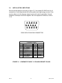
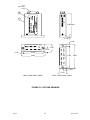
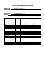
INSTALLATION MANUAL AND
OPERATING INSTRUCTIONS
MD41-( ) Series GPS Annunciation Unit
For Garmin GNS 430/430W/530/530W VHF
Communication and Navigation Management System
MD41-1484W
MD41-1488W
MD41-1494W
MD41-1498W
14VDC
28VDC
14VDC
28VDC
MID-CONTINENT INST. CO., INC
Horizontal Mount
Horizontal Mount
Vertical Mount
Vertical Mount
MANUAL NUMBER 9016478
Revision History
ECO
4828
REV. C
Rev.
N/R
A
B
Date
01/19/07
02/15/07
03/12/07
C
4/24/07
Detail
Initial release.
J1 connector was 9016475, now 9016479.
Corrected section 4.1 to show proper pins,
corrected mating connector rear view.
Correct connector schematic pinout in section
1.2.5. Add –1494W and –1498W versions.
2
April 24, 2007
TABLE OF CONTENTS
SECTION 1
1.1
1.2
1.2.1
1.2.2
1.2.3
1.2.4
1.2.4.1
1.2.4.2
1.2.5
1.2.6
1.2.7
GENERAL DESCRIPTION
INTRODUCTION
SPECIFICATIONS, TECHNICAL
PHYSICAL CHARACTERISTICS
ENVIRONMENTAL CHARACTERISTICS
SPECIFICATIONS, ELECTRICAL
FRONT PANEL CONTROLS AND ANNUNCIATIONS
CONTROLS
ANNUNCIATIONS
INTERFACE
EQUIPMENT LIMITATIONS
MAJOR COMPONENTS
SECTION 2
2.1
2.2
2.3
INSTALLATION CONSIDERATIONS
COOLING
EQUIPMENT LOCATION
ROUTING OF CABLES
SECTION 3
3.1
3.2
3.3
3.4
INSTALLATION PROCEDURE
GENERAL INFORMATION
UNPACKING AND INSPECTING
MOUNTING THE MD41-( )
INSTALLATION LIMITATIONS
SECTION 4
4.1
4.2
POST INSTALLATION CHECKOUT
PRE-INSTALLATION TEST
OPERATING INSTRUCTIONS
FIGURES
3.1
3.2
3.3
3.4
LIST OF ILLUSTRATIONS
SCHEMATIC PINOUT, 15 PIN HIGH DENSITY D-SUB
OUTLINE DRAWING
INSTRUMENT PANEL MOUNTING
WIRING DIAGRAM, MD41-1484W/1488W/1494W/1498W
APPENDIX
RTCA DO-160C ENVIRONMENTAL QUALIFICATION FORM
REV. C
3
April 24, 2007
SECTION 1 GENERAL DESCRIPTION
1.1
INTRODUCTION
The MD41-( ) is a compact, self-contained GPS Annunciation unit. This unit
displays status annunciation received from the Garmin GNS 430/430W/530/530W
series GPS navigation management systems.
Features include dual 20,000 hour lamps used for all annunciations along with
automatic photocell dimming. An external annunciation dimming adjustment is
provided for balancing low-level light conditions.
1.2
TECHNICAL SPECIFICATIONS
1.2.1 PHYSICAL CHARACTERISTICS
Mounting:
Width:
Height:
Depth:
Weight:
Front mount, panel
2.45 inches
0.75 inches
2.60 inches (max)
0.2 pounds
1.2.2 ENVIRONMENTAL CHARACTERISTICS
REV. C
TSO Compliance:
Applicable Documents:
TSO C129
RTCA DO-160C, DO-208
Operating Temperature Range:
Humidity:
Altitude Range:
Vibration:
Operational Shock:
-55°C to +70°C
95% Non-Condensing
0 to 55,000 ft.
RTCA DO-160C, Cat. M and N
Rigid Mounting, 6G Operational
15 G Crash Safety
4
April 24, 2007
1.2.3
ELECTRICAL SPECIFICATIONS
Design
MD41-1484W (14VDC)
MD41-1488W (28VDC)
MD41-1494W (14VDC)
MD41-1498W (28VDC)
All Solid State
0.30 Amps
0.25 Amps
0.30 Amps
0.25 Amps
1.2.4 FRONT PANEL CONTROLS AND ANNUNCIATIONS
1.2.4.1
ANNUNCIATIONS
VLOC
GPS
MSG
WPT
TERM
APR
INTG
NAV or ILS information presented on the HSI or CDI
GPS information presented on the HSI or CDI
ON indicates message(s) active.
ON indicates reaching the arrival waypoint.
ON indicates aircraft is within 30 miles of departure or
arrival airport
ON indicates the approach is active.
ON indicates GPS receiver detected a position error
or is unable to calculate the integrity of the position
1.2.5 INTERFACE
INTG annunciation
J1 Pin 1
Requires a logic low to annunciate
WPT annunciation
J1 Pin 2
Requires a logic low to annunciate
when in VOR/ILS mode
MSG annunciation
J1 Pin 3
Requires a logic low to annunciate
TERM annunciation
J1 Pin 4
Requires a logic low to annunciate
APR annunciation
J1 Pin 6
Requires a logic low to annunciate
VLOC annunciation Receives ground from GNS 430/530
J1 Pin 7
REV. C
GPS annunciation
J1 Pin 8
Receives ground from GNS 430/530
when in GPS mode.
Lamp Test
J1 Pin 10
Receives ground from remote test switch
to light all annunciations (optional connection)
J1 Pin 15
Ground
5
April 24, 2007
1.2.6 EQUIPMENT LIMITATIONS
The MD41-( ) series control units contain specific dash numbers to be used with
various GPS receivers or Navigation Management Systems. The installer must match
the correct controller part number with the system being installed.
The conditions and tests required for TSO approval of this article are minimum
performance standards. It is the responsibility of those desiring to install this article
either on or within a specific type or class of aircraft to determine that the aircraft
installation conditions are within the TSO standards. The article may be installed
only if further evaluation by the applicant documents an acceptable installation and
is approved by the Administrator.
The MD41-1484W/1488W/1494W/1498W are TSO certified and approved for use
with the Garmin GNS 430/430W/530/530W system. This includes the (A), (W) and
TAWS system versions of the Garmin equipment. Any attempts to install the listed
units in an installation other than the GNS 430/530 system is prohibited.
This will void the TSO.
NOTE:
If the MD41-( ) is disconnected or removed from the aircraft, it will not
affect the operation of the GNS 430/430W/530/530W.
1.2.7 MAJOR COMPONENTS
This system is comprised of one major component, the MD411484W/1488W/1494W/1498W GPS Annunciation Control Units.
REV. C
6
April 24, 2007
SECTION 2: INSTALLATION CONSIDERATIONS
2.1
COOLING
No direct cooling is required. As with any electronic equipment, overall reliability may
be increased if the MD41-( ) is not located near any high heat source or crowded next
to other equipment. Means of providing a gentle airflow will be a plus.
2.2
EQUIPMENT LOCATION
The MD41-( ) must be mounted as close to the pilot’s field of view as possible. The
preferable location is near the HSI/CDI that will be displaying the GPS/VLOC
information. The unit depth, with connector attached, must also be taken into
consideration. Note: Unlike previous versions of the MD41 Annunciation Control Units
(ACU), the transfer relays are not required since the GNS 430/530 handles all
switching between GPS, VOR and ILS. This has allowed for a smaller size ACU that
now provides more options for panel mounting.
2.3
ROUTING OF CABLES
Care must be taken not to bundle the MD41-( ) logic and low level signal lines with
any high energy sources. Examples of these sources include 400 HZ AC, Comm,
DME, HF and transponder transmitter coax. Always use shielded wire when shown
on the installation print.
Avoid sharp bends in cabling and routing near aircraft control cables.
REV. C
7
April 24, 2007
SECTION 3: INSTALLATION PROCEDURES
3.1
GENERAL INFORMATION
This section contains interconnect diagrams, mounting dimensions and other
information pertaining to the installation of the MD41-( ). After installation of cabling
and before installation of the equipment, ensure that power is applied only to the pins
specified in the interconnect diagram.
3.2
UNPACKING AND INSPECTING EQUIPMENT
When unpacking equipment, make a visual inspection for evidence of damage
incurred during shipment. The following parts should be included:
3.3
1.
MD41-1484W (14VDC) or MD41-1488W (28VDC) Horiz. Mount
MD41-1494W (14VDC) or MD41-1498W (28VDC) Vertical Mount
2.
Installation kit P/N 9016480 consisting of the following items:
A. J1 Connector Kit (15 pin)
MCI P/N 9016479
B. 2 ea mounting brackets
MCI P/N 8018483
C. 4 ea 4-40x ½ pan Phillips screws
MCI P/N 90-416-00011
D. 2 ea 4-40x 9/16 flat Phillips screws
MCI P/N 90-418-10011
E. 1 ea panel cutout template
MCI P/N 8018954
3.
Installation Manual
MCI P/N 9016478
MOUNTING THE MD41-( )
Plan a location in the aircraft for the MD41-( ) to be mounted as close to the pilot’s
field of view as possible. The preferable location is near the HSI/CDI that will be
displaying the GPS information. Avoid mounting close to heater vents or other high
heat sources. Allow a clearance of at least 3 inches from back of unit for plug
removal.
Use the dimensions shown in figure 3-3 to prepare opening and screw holes for the
ACU. A file template has been provided to use for these measurements and hole
cutout Carefully measure the locations for the screw holes and mark the drill locations
with a center punch. Drill all six holes. A steel template (P/N 8018954) is supplied to
aid in locating holes and cutting out the panel. The template may be mounted to the
instrument panel to allow a file to be used to complete the cutout area. The front plate
of the ACU has a recessed area on the back so a flat head screw is not absolutely
necessary. Attach the mounting brackets to the rear side of the instrument panel with
four 4-40x1/2 pan-head screws. Insert the ACU through the front of instrument panel
and fasten with two 4-40 x 9/16 flat-head screws.
REV. C
8
April 24, 2007
3.4
INSTALLATION LIMITATIONS
Wire the aircraft harness according to figure 3-3. Use at least 24 AWG wire for all
connections. Avoid sharp bends and routing cable near high-energy sources. Care
must be taken to tie the harness away from aircraft controls and cables. Normal
installation techniques should be applied. Also see equipment limitations, section
1.2.6.
REAR VIEW OF MATING CONNECTOR
Connector Pinout
Pin #
Pin #
1 INTG Annun.
9
2 WPT Annun.
10
3 MSG Annun.
11
4 TERM Annun.
12
5 28 VDC Power
13
6 APR Annun.
14
7 VLOC Annun.
15
8 GPS Annun.
Reserved
Lamp Test
Reserved
Reserved
Reserved
Reserved
Ground
FIGURE 3-1 SCHEMATIC PINOUT, 15 PIN HIGH DENSITY D-SUB
REV. C
9
April 24, 2007
15-pin
High Density
D-Sub
2.392 MAX
0.150
0.150
0.750
0.375
0.150
2.150
2.450
2.150
2.450
0.375
0.750
MD41-1484W, MD41-1488W
MD41-1494W, MD41-1498W
FIGURE 3-2 OUTLINE DRAWING
REV. C
10
April 24, 2007
FIGURE 3-3 INSTRUMENT PANEL MOUNTING
REV. C
11
April 24, 2007
MD41-( ) ACU
J1
1A
AIRCRAFT PWR
POWER GND
APR ANN
TERM ANN
WPT ANN
MSG ANN
VLOC ANN
GPS ANN
INTG ANN
LAMP TEST
TO MD41-ACU
CIRCUIT BREAKER
P4001
GNS 430/430W
P5001
GNS 530/530W
NOTES:
1) REFER TO GARMIN GNS 430, 430W or GNS 530, 530W INSTALLATION
MANUAL FOR ACTUAL INSTALLATION.
2) ALL WIRING SHALL BE 24 AWG UNLESS OTHERWISE NOTED.
3) MOMENTARY SWITCH FOR TEST. (optional connection)
4) 14 VDC FOR MD41-1484W/1494W. 28 VDC FOR MD41-1488W/1498W.
FIGURE 3-4: WIRING DIAGRAM, MD41-1484W/1488W/1494W-1498W
For GARMIN GNS 430/430W/530/530W
REV. C
12
April 24, 2007
SECTION 4: POST INSTALLATION CHECKOUT
4.1
PRE INSTALLATION TESTS
With the MD41-( ) disconnected, turn on the avionics master switch and verify that
aircraft power is on pin 5. Using an ohmmeter, verify pin 15 is aircraft ground.
4.2
OPERATING INSTRUCTIONS
Turn off the avionics master switch and connect the mating connector to the rear of
the MD41-( ). Turn on the avionics master switch and the MD41-( ) should come on
with the following annunciations.
1.
2.
VLOC or GPS
MSG may be flashing depending on the status of the GPS receiver.
Annunciation brightness at the minimum dimming level may be adjusted by rotation of
the dimmer control located on the side of the MD41-( ) case. CW rotation lowers the
dimming level.
Refer to section 5 of the Garmin GNS 430/430W or GNS 530/530W installation
manual for testing of annunciations.
No periodic maintenance or calibration is necessary for continued airworthiness of
the MD41-( ).
REV. C
13
April 24, 2007
DO-160C Environmental Qualification Form
NOMENCLATURE:
Annunciation Control Unit (ACU)
MODEL NUMBER:
MD41-( ) Series
TSO NUMBER: C129, Class A1
MANUFACTURERS SPECIFICATIONS:
Minimum Performance Specification 7015613
Test Data Specification (TDS) 161, dated 2/12/07
MANUFACTURER:
ADDRESS:
Mid-Continent Instrument Co., Inc.
CONDITIONS
Temperature and Altitude
Survival Low Temperature
Operating Low Temperature
Temperature Variation
Humidity
Operational Shocks and Crash
Safety
Vibration
Explosive Atmosphere
Waterproofness
Fluids Susceptibility
Sand and Dust
Fungus
Salt Fog
Magnetic Effect
Power Input
Voltage Spike
Audio Frequency Conducted
Susceptibility
Induced Signal Susceptibility
Radio Frequency Susceptibility
(Radiated and Conducted)
Emission of Radio Frequency
Energy
Lightning Induced Transient
Susceptibility
Lightning Direct Effects
Icing
REV. C
DESCRIPTION OF TEST
Equipment tested to Category A1F2
SECTION
4.0
4.5.2
4.5.2
5.0
6.0
7.0
Equipment tested to Category B
Equipment tested to Category A
Equipment tested to Paragraph 7.2.1
8.0
9.0
10.0
11.0
12.0
13.0
14.0
15.0
16.0
17.0
18.0
Equipment tested to Category M and N
Equipment identified as category X, no test performed.
Equipment identified as category X, no test performed.
Equipment identified as category X, no test performed.
Equipment identified as category X, no test performed.
Equipment identified as category X, no test performed.
Equipment identified as category X, no test performed.
Equipment tested to Category Z
Equipment tested to Category B
Equipment tested to Category A
Equipment tested to Category B
19.0
20.4
20.5
21.0
Equipment tested to Category A
Equipment tested to Category T
22.0
Equipment identified as category X, no test performed.
23.0
24.0
Equipment identified as category X, no test performed.
Equipment identified as category X, no test performed.
Equipment tested to Category Z
14
April 24, 2007