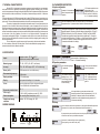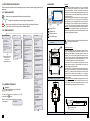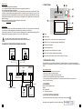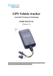
1
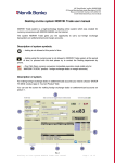
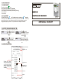
11. REPORT PRINTOUT.
11.1. BRIEF REPORT.
To print the report press
button
The type of brief report can be set in 4.10 parameter:
- actual measurements (current recorder measurements)
- from the delivery (from the last delivery, from loading to unloading)
- from the last hour
- from current day
DR-101
TEMPERATURE RECORDER
11.2. FULL REPORT.
To start the printout press
button. To stop the printout at any moment press
button again.
In this mode, the recorder prints all data from the memory from the newest measurements to the oldest. By
means of this function you can print data from any period of time, from the beginning of the printout
stopping data printing at any moment. The report includes sensors description and user data.
11.3. REPORT FROM GIVEN PERIOD OF TIME.
In this mode, recorder prints data from the specified period of time.
Press
button to enter the
1.1 Print from...
1.Print from..
menu and select “Print from...” 01/03/2006 00:00
with
button.
1.2 Print to...
31/03/2006 23:59
Press
button and enter
the end of printing with
navigation buttons and confirm
with
Press
and confirm
the beginning of the printing
with navigation button and
confirm with
Recorder prints the report
ended up with header and
exits from the configuration
menu.
Printing....
12. PRINTOUT DESCRIPTION.
DR-101 v.1 Serial No.: 201105001
..........................................................................
termoplus Slawek Banka
Vehicle No.: RST 25FJ NR001
..........................................................................
D1 = door
T1 = front of the
D2 = defrosting
trailer
Model and serial number
User data
Registration number
..........................................................................
Recorder has a “delivery”
function, which allows you to
record the beginning and the
ending of the drive on the
report (loading and
unloading).
Date:
Time:
01-05-2011 12:00
12:15
12:30
Loading : 12:32
12:45
13:00
13:01
13:15
13:28
13:30
13:45
Unloading: 13:50
14:00
14:02
14:15
01-05-2011 14:30
T1:
24.1
24.2
24.3
24.4
25.1
25.2
26.1
26.2
16.7
10.5
8.5
9.8
10.5
EE
10.5
8.8
D1:
D2:
Signature:
........................................................................
Temperature alarm
Registered events:
e.g. Door opening
Sensor error
Signature
USER MANUAL / WARRANTY
Version 2.0
1. TECHNICAL CHARACTERISTICS.
Recorder DR-101 is designed to temperature measurement and recording from one temperature
sensor and events from two digital inputs (door opening, aggregate operation, defrosting cycles). The curret
value of the temperature and emergency states are displayed on back-lit, alphanumeric display. Measurement
data is stored in non-volatile recorder memory. The frequency of data memorizing can be set in 1...999minutes
range.
The memory has capacity of 32 000 measurements (lasts for about YEAR at a frequency of memorizing every
15 minutes). When memory is full, the reocrder continues operating and the oldest measurements are replaced
by the newest. The stored data can be deleted and the access to the mnu can be password protected.
The recorder is equipped with a thermal printer that enables current of memory data printout from
given period of time. User data, vehicle and sensors description, course of temperature in time, events from
digital inputs, temperature emergency states, loading and unloading time and place for signature are printed on
every report. The report allows to check the whole history of transport by the final consignee. The user can set
minimum and maximum temperature, which when exceeded will be signalled on the display, by the beeper and
by active states of the relay. Operation of the device is very simple and intuitive, all messages and
communicates are displayed in English. One temperature sensor with 5m wire is included. Recorder has a
“delivery” function, which enables the users and the customers to identify the beginning and the ending of the
drive on the printed report.
Device is designed to control the transport and it is powered by vehicle electrical installation
12...24V or stationery version with 230V mains power. There are also available door opening sensors,
external sounders and device calibration certificate.
10.4 PARAMETERS DESCRIPTION:
A. Inputs configuration
Parameter 3.1 determines the
status of temperature sensor
operation.
3.3 Calibr. T1
0.0°C
When the temperature deviates from the actual value, you can calibrate the
temperature sensor. 3.3 parameter value is added to the measured value.
3.4 Input D1:
off
on - NO
on - NC
Thermograph is equipped with 2 digital inputs and events recording (door opening,
aggregate operation, defrosting cycles) and loading and unloading time. The type of
each input is defined by 3.4 and 3.6. parameters. “LOADING” and “UNLOADING”
commands are triggered by shorting signal fed to the digital input D1. Connect the
circuit with shorting element to 4-5 contacts, e.g. With common bell button. Shorting
the circuit of 4-5 contacts, commands will be triggered and saved in the memory.
Commands are indicated on the display:
3.6 Input D2:
off
on - NO
on - NC
“delivery” function
T1=20.1°C
T1=20.1°C
T1=20.1°C
T1=20.1°C
2. SPECIFICATIONS
Inputs:
Temperature sensor: NTC 5k by 25°C
2 digital inputs (normally opened or closed)
Measuring range:
NTC: -40...+120°C (-40...+80°C - wall sensor)
Accuracy:
NTC in: -40...+80°C range: ±0,5°C, ±1°C in other range
Memory buffer
32 000 measurements, non-volatile memory
Data memorizing frequency:
1...999 minutes
Display resolution:
0,1°C in whole range
Display:
Liquid crystal with backlight, 2 x 16 characters
Printer:
Thermal, printing speed 30mm/s, heat-sensitive paper
57,5mm ±0,5mm width, roll diameter 35mm
Degree and protection class:
IP65 / II
Power supply:
12...24V=/~±20%, for stationary version: 85...265V~
Power consumption:
When recording 50mA, when printing - to 3A
Operation and storage
conditions:
operation: -30...50°C; storage: -40...60°C
3.5 Input description D1:
- Loading
10:15
Delivery-
3.7 Input description D2:
T1=20.1°C
°C
T1=20.1
10:15
Unloading
- Unloading
Delivery
3.5 and 3.7. Parameters enable to
enter descriptions of digital inputs (e.g.
“Doors” - 16 characters maximally).
B. Operation parameters.
4.1 Language:
Polish
English
German
You can select language in
4.1 parameter.
4.2 Date, time:
19/12/2006 22:34
You can set current date and
time in 4.2 parameter.
4.3 Sampling period
15 min
This parameter enables to set
sampling time in 1...999
minutes range (frequency of
data memorizing to the
recorder memory)
4.8 Backlight
on
off
“ON” - display backlit all time
“OFF” - display backlit when
using, 20 sec after last touch
goes out
4.4 User data L1:
4.6 User data L3:
4.5 User data L2:
4.7 Registration number
In the report header you can enter user data or brief
description consisted of three lines (parameters 4.4, 4.5, 4.6,
maximally 32 characters) and the recorder identification
number and/or vehicle registration number (parameter 4.7.,
16 characters maximally).
D. Alarmy
2.1 Alarm function:
on
off
D2
Digital inputs
(closed/opened)
User can activate an alarm function (parameter 2.1) and program MIN and MAX temperature
(parameters 2.2, 2.3) which, when exceeded will be indicted on the display, e.g.
T1=50.0°C
T1=50.0°C
20:15
T1 MAX
By beeper and relay active state. Beeper can be muted by any button. Emergency states will
be saved in recorder memory and marked on the printout.
D1
2
10:15
Loading
3.2 Sensor T1 desription
C. User data.
3. WIRING DIAGRAM.
Temperature
sensor
3.2. Parameter enables to enter
the description of the
temperature sensor (e.g. Cold
store, rare/front of semi-trailer,
etc. - 16 characters maximally).
3.1 Sensor T1:
on
off
Power supply
2.4 Alarm delay
0 min
Parameter 2.6 enables defining an alarm signalling delay
(alarm signalling occurs after the daley time).
Alarm
6
10. RECORDER CONFIGURATION.
4. MOUNTING.
Recorder.
After mounting the recorder and all measuring sensors, connect the power supply and configure
the device.
10.1. MENU HANDLER.
- starts menu and parameters edition and accepts changes
- changes the parameters values and passes between them
- backs up one level higher in the menu nad exits from the configuration menu,
it is also used to go back to the previous character edition
Recorder DR-101
10.2. MENU DIAGRAM.
Aggregate relay
When choosing an assembly location you have to remember
that the casing of the recorder is non resistant to difficult
environment conditions. Therefore, it should be mounted in the
vehicle trailer. You have to remember to tighten the cover of the
electrical connectors and wires glands firmly and to close the
casing doors properly.
Before mounting you should mark places for holes accroding to
dimensions (see: Pic.2) or try on the recorder. Then drill holes
with a diameter of 5 mm and tighten with screws or drill holes
with a diameter of 4 mm and tighten screws with a diameter of
4,5 mm. Wires should be led through waterproof glands
separately. Try on use existing raceways for wires assembly. If it
is essential to use separate raceways, you should use selfadhesive ones and where the holes are drilled you have to seal
them with an appropriate substance.
Temperature sensor
1.2 Print to...
30-05-2011 23:59
Printing....
Report printout from
a period of time
and exit from
configuration menu
3.Inputs.
2.1 Alarm function:
On
Off
3.1 Sensor T1:
On
Off
2.2 Minimum
1.3
T1 MIN: T1:
-50°C
-40°C
3.2 Sensor description T1
Temperature sensor 1
2.3 T1 MAX:
120°C
3.3 Calibration T1
0.0°C
2.4 Alarm delay
3 min
3.4 Input D1:
Off
On- NO
On- NC
3.5 Input description D1:
Defrosting
3.6 Input D2:
Off
On - NO
On- NC
Delivery function
3.7 Input description D2:
Delivery
10.3. MEMORY CLEARING.
Attention!
After running this function, all data will be
IRRECOVERABLE!
To delete the data, enter 4.13 parameter, set “YES”
and confirm with
button.
Memory clearing process is signalled by command
on the display:
Data deletion ..
4.Configuration.
4.1 Language :
Polish
English
German
Door opening sensor
Pic.1 The example of the recording system
in the truck.
4.2 Date,time :
01-05-2011 22:34
125
4.3 Sampling time.
15 min
4.4 User data L1:
4.5 User data L2:
4.6 User data L3:
4.7 Registration number
149
4.8 Backlight
On
Off
Pic.2 Recorder casing dimensions.
4.9 Signalling
Sound on
Sound off
46
Temperature sensors.
Recorder is equipped with one temperature sensor (wired or
casing). Temperature sensor should be mounted in a cold
chamber in a safe place, not exposed where is a proper air
circulation. The source of indoor lighting should not be closer
than 50 cm from the sensors. The recommended location of the
sensors is on the wall 30 cm from the ceiling, properly 1/3 or 2/3
of the chamber length from the outlet of the evaporator.
Wired sensor (Pic.3) is mounted in a vertical position with an
ending upwards, directly on the wall inside the chamber by
means of clamps and fixing chucks.
Casing sensor (Pic.4) is mounted on the wall using screws or
bolts. It should be installed in a vertical position with an ending
upwards. Try on the sensor and mark places for holes before
mounting.Drill the holes with a diameter of 4 mm.Supply
conduct should be connected to stirrup bolts and led through
waterproof gland.
Sensors does not require maintaining wiring polarity. To extend
the sensors use standard OMY wires with a section not less
than 0,75mm2. Maximum wire length should not exceed 100
meters depending on quality and section of used wire.
4.10 Brief printout
Actual measurements
From delivery
From the last hour
From today
4.11 Factory settings
Do not restore
Data restore
4.12 Data delete ?
No
Yes
50
4.13 Password :
000
Ip67 protection class
Pic.3. Casing sensor dimensions.
5
Remember to make sure that all drilled holes are sealed
by aprropriate silicon sealant. .
33
1.1 Print from...
01-05-2011 00:00
2.Alarms.
183
1.Print from selected day
5 or 10m
20
Rys.4 Wymiary czujnika naściennego.
Pic.4. Wiring sensor dimensions.
3
Digital sensors.
6. FRONT PANEL.
Thermograph is equipped with 2 digital inputs:
- D1 for events recording (door opening, defrosting cycles, aggregate operation etc.).
- D2 for loading and unloading time recording
The type of each event sensor is defined by 3.4 and 3.6 parameters (normally closed/ normally opened). When
connecting contacts signalling the aggregate operation or defrosting cycles to digital input, you have to be
particularly careful so that no signalling circuit is not a live both in active or inactive state. Otherwise, the recorder
will breakdown. Signalling relies on short-circuiting or opening the circuit of digital input only, rather than the
transfer of charge!
Each closing and opening the circuit is recorded in the recorder memory.
The sensors do not require wiring polarity.
Power supply.
SEL
Recorder is powered from the vehicle electrical installation 12V and 24V. You can connect the recorder directly
from the battery, fuse lath or aggregate. You should protect the power source with 5A fuse.
Power supply is connected to 11 (-) and 12 (+) terminals. Maximum power consumption (when printing) is 50W.
Stationery version is powered by mains with 110V~ or 230V~ 50/60Hz voltage.
LF
Display
Thermal printer
The value of supply voltage is marked on the vehicle rating plate.
It is prohibited to operate with electric cables when the unit is energized!!
Confirming button, it is also used to run the configuration menu
ON/OFF (hold for 5 seconds) and changes cancelling button
5. SAMPLE OF THE RECORDER WIRING DIAGRAM.
Brief report printing button
Full report printing button
Door sensor
e.g. Reed relay
“Delivery” function
button
Flap opening in order to install a new roll of paper
Back-lit button for printer operating status signalling
A
B
A
Printer feeding back-lit button, it is also used for pulling out the paper
B
7. PAPER INSTALLATION.
Alarm
Put an included roll of thermal paper in the printer. The thermal paper used for printing is standard and
available in every stationery point of sale.It is recommended to use rolls of a width of 57mm and diameter of
35mm.
DR101
How to install the paper:
1. Press the flap dropout button on the front panel.
2. Put the roll of paper in the printer chamber
3. Pull out about 3 cm of paper outside the printer flap
4. Close the flap controlling that the paper came out correctly
5. If it is necessary pull out the paper using “LF” button (red button/ SEL diode must be turned off
so that “LF” button be active).
Red
White
Digital inputs
(opened/closed)
Fuse 5A
Access to the configuration menu.
Setting:
000 - password off
211 - emergency password
Temperature sensors
External
alarm
indicator
8. PASSWORD.
Accumulator
9. FACTORY SETTINGS RESTORE.
To restore parameters to the factory settings, set “data restore” and confirm with
Restoring process is signalled by command on the display:
4
Data restoring..
5