1
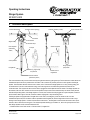
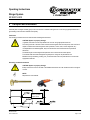
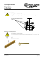
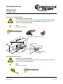
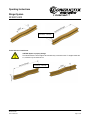
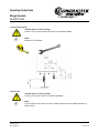
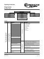
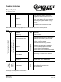
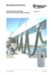
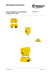
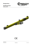
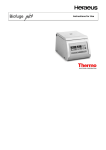
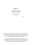
Operating Instructions
Stinger System
03-W001-0400
BAL0300-0009-E
www.conductix.com
Page 1 of 24
Operating Instructions
Stinger System
03-W001-0400
Index
Page
1
Introduction .............................................................................................................................................................................. 2
2
Target Group............................................................................................................................................................................ 3
3
Designated application............................................................................................................................................................. 3
4
General safety instructions ...................................................................................................................................................... 4
5
Technical description ............................................................................................................................................................... 8
6
Operation ................................................................................................................................................................................. 9
7
Technical data........................................................................................................................................................................ 10
8
Transport and installation....................................................................................................................................................... 12
9
Commissioning ...................................................................................................................................................................... 18
10
Maintenance .......................................................................................................................................................................... 19
11
Disposal ................................................................................................................................................................................. 23
12
Spare parts list ....................................................................................................................................................................... 23
1 Introduction
This operating manual is part of the Stinger System. Prior to commissioning, ensure that operating personnel has read and
understood these instructions. Use the Stinger System only according to its designated application (see chapter „Designated
Application”).
This documentation is protected by copyright law. The rights established herein, including translation, reprinting, the use of figures,
radio transmission, reproduction using photographic or similar methods or saving in electronic format remain reserved, even for
partial use.
Conductix-Wampfler reserves the right to make technical changes without informing the recipient of this document / these data.
Conductix-Wampfler accepts no liability, inasmuch as this is legally permissible, for errors in this documentation or for damages
that occur in connection with delivery and use of the documentation.
© Conductix-Wampfler AG 2008
BAL0300-0009-E
www.conductix.com
Page 2 of 24
Operating Instructions
Stinger System
03-W001-0400
2 Target Group
ONLY AUTHORIZED AND QUALIFIED MAINTENANCE PERSONNEL MAY WORK WITH THE STINGER SYSTEM.
Such persons are the target group for this manual.
A qualified person is anyone correctly trained and authorized to operate the energy supply system in compliance with relevant
standards, regulations and laws. In addition, a qualified person has the special education and skills necessary to recognize and
avoid risks and possible dangers which may occur during operation.
Maintenance and repair on the electrical system and on electrical equipment of the Stinger System may only be performed by
authorized and qualified technicians in compliance with the relevant electrotechnical rules, regulations and laws.
Maintenance and repair on the mechanical system may only be performed by authorized and qualified persons in compliance with
the relevant technical standards, regulations and laws.
3 Designated application
The Stinger System is a power supply for rail vehicles, which are located in a maintenance and repair area and separated from
their main power supply.
The system supplies sufficient power for operating the onboard systems and for moving the rail vehicle slowly by drive*, within a
limited area.
During operation, the load on the Stinger System must not exceed a certain limit*.
The system is a passive power supply. All electric and electronic control, surveillance and protection functions are not part of the
system and under the responsibility of the operator.
NOT a designated application is ...
...
...
...
...
...
...
...
...
...
...
if the rail vehicle is moved and the speed exceeds a certain limit*.
if the rail vehicle is moved out of the defined maintenance and repair area.
if the electric load on the Stinger System exceeds a certain limit*.
if electric loads are connected to the Stinger System, which are not designated to the rail vehicle.
if the length of the Stinger connection cable has changed.
if the length of the Stinger connection cable has shorten by loops or by coiling or binding of cable sections.
if the Stinger connection cable is coiled around other objects.
if the Frangible Link is by-passed or removed mechanically.
if the Stinger connection cable is separated at the Frangible Link.
if the plastic shear rod of the Frangible Link is removed and a third party part is installed (e.g. a metal rod).
BAL0300-0009-E
www.conductix.com
Page 3 of 24
Operating Instructions
Stinger System
03-W001-0400
...
...
…
…
…
if the Stinger connection cable is removed from the rail vehicle under load.
if the Stinger System gets in contact with liquids (water, detergents...). Do not use a high pressure cleaner nearby !
if inappropriate cables are used
if atmospheric conditions (including a change to projected physical location) are changed
if technically inappropriate guide systems (such as inappropriate or corroded track beams, poorly aligned girder joints, etc.) are
used
… if there is a presence of projecting edges on the surrounding steel framework at insufficient distance from the cable trolley
* = refer to chapter „Technical data“
The manufacturer is in no way liable for damages to the system or third parties resulting from non-intended use.
The Stinger System is built in accordance with recognized safety/technical regulations using current technology and has been
checked for safety compliance by the manufacturer. Only Stinger Systems that are in good technical condition may be employed
for their intended use. These may only be operated by personnel aware of safe operating practices and possible hazards. Intended
use of the system also includes the observance of manufacturer operation, service, and maintenance requirements.
4 General safety instructions
The following symbols and references are used in this manual to give instructions and warnings (cautions) of particular importance.
These must always be strictly observed!
*
NOTE:
Refers to special information on how to use the equipment safely and efficiently.
CAUTION:
Warns of general dangers. Danger of injuries and damage to property. Take care!
CAUTION:
Warns of danger of electrical shock from live equipment.
The operating instructions must always be kept at an on-site location near the Stinger System where they can be readily accessed.
In addition to the operating instructions, general regulations regarding accident prevention and environmental protection are to be
observed.
BAL0300-0009-E
www.conductix.com
Page 4 of 24
Operating Instructions
Stinger System
03-W001-0400
The operator must observe following for operation of a Stinger System:
• Installation, activation, maintenance and operation of the Stinger System must be performed by sufficiently qualified and
trained specialists.
• Before beginning work, operation and maintenance personnel must have read and understood the operating instructions and
safety regulations, in particular. Protective gear for operation and maintenance personnel must be provided and used.
• The system operator or his/her representative is to supervise machine operation to ensure that personnel use caution when
working on or with the system.
Special safety notes
Transport / Installation:
• Individual parts and larger assembly groups are to be secured on suitable hoisting devices or load-carrying equipment that are
in good working order and have sufficient load capacity.
For electrical and mechanical connections:
• Connections are only to be made by personnel specially trained for the given task.
For commissioning and operation:
• Before initial commissioning and daily start-up, a visual check and predefined inspection procedure is to be performed as
described in chapter 4.
• Any procedures that could negatively affect safety are to be avoided.
• The system should only be operated with functional protective gear and safety devices.
• Notify the responsible party immediately in case of damage to the Stinger System.
• Protect the Stinger System from accidental or unauthorized operation.
For cleaning / service / repair / maintenance / reconditioning:
•
•
•
•
•
•
•
•
•
•
•
•
•
Turn off power supply and ensure that no unauthorized activation is possible.
When installation tasks are carried out above eye level, use proper climbing aids and working platforms.
Do not climb on machine components.
Check cables for wear or damage.
Ensure that exhaust, collection and disposal of process materials be done in a safe and environmentally-friendly manner.
Safety devices that are removed for installation, service or repair must be remounted and inspected after work is completed.
Observe the inspection and maintenance intervals
Observe the directions in the operating and maintenance instructions for replacing parts.
Ensure that sufficient space for maintenance work is available.
Ensure that the Stinger System is not unexpectedly activated during maintenance work.
Ensure that detached parts do not fall.
Screw joints that are disconnected during maintenance work are to be rejoined and secured as instructed.
Fasteners and seals that cannot be used again are to be replaced (such as self-locking nuts, disks, splints, O-rings, glued or
microencapsulated screws).
BAL0300-0009-E
www.conductix.com
Page 5 of 24
Operating Instructions
Stinger System
03-W001-0400
• Lubrication points that are cleaned or wiped during maintenance and repair work must be re-lubricated as instructed.
• After finishing work, collect all tools and materials and check that all are present.
• Detached parts and components that were replaced are to be collected, stored in a safe place, recycled, or sent back.
Hazard areas must be identified with warning signs and be protected with barriers. Ensure that hazard area notices are observed.
Hazards can result from
• Improper use
• Failure to adequately observe safety notices
• Inadequate inspection and maintenance work
Mechanical hazards
WARNING! Bodily harm!
Unconsciousness and injury due to
- crushing, pinching, cutting, wrapping
- retracting, blunt collision, stabbing, grinding
- slipping, stumbling, falling.
Causes:
Areas where danger of crushing, pinching and wrapping exists
- Part failure or explosion
Ways to protect yourself:
- Keep floors, devices, and machines clean.
- Repair leaks.
- Observe the required safety distance.
Electrical hazards
All errors must be analyzed before remedying the problem.
Work on electrical systems or production equipment may only be performed by specialized electricians or persons under the
supervision and direction of an electrician in accordance with electrical rules (qualified personnel).
WARNING! Bodily harm!
Death due to electric shock, injury and burns due to
- Touching live sources
- Inadequate maintenance and repair
- Faulty insulation
- Short circuits
Causes:
Touching or coming too close to uninsulated current-bearing parts
- Using uninsulated tools
- Current-bearing parts that are laid bare due to insulation failure
- Inadequate safety checks after maintenance work
- Use of improper fuses
BAL0300-0009-E
www.conductix.com
Page 6 of 24
Operating Instructions
Stinger System
03-W001-0400
Ways to protect yourself:
• Ensure that current to machines and system parts that are to undergo maintenance work is turned off and protected against
reactivation.
• Check parts to ensure that they are free of current. Cover and isolate nearby live parts.
• Check electrical equipment regularly
• Immediately replace loose or damaged cable or lines
• Always replace blown fuses with identical fuses
• Avoid touching live parts
• Use insulated tools.
Repeat inspections
Every owner is to record all inspection, service and maintenance tasks in a machine book in an orderly manner. This is to be
confirmed by a technical expert. In case of inaccurate or missing entries, the warranty is rendered null and void.
CAUTION! System or property damage!
Devices and systems are to be periodically inspected by an expert. In general, visual and functional
checks are to be performed. The condition of components with regard to damage, wear, corrosion or other
damage is to be determined. Furthermore, completeness and functionality of the safety equipment is
evaluated. To better evaluate the wear and tear of parts, disassembly may be required.
CAUTION! System or property damage!
All regular inspections are to be performed by the owner.
BAL0300-0009-E
www.conductix.com
Page 7 of 24
Operating Instructions
Stinger System
03-W001-0400
5 Technical description
Current collector 0813
Conductor rail 0813 (Energy)
Current collectors 0811
Conductor rail 0811 (Control)
Track beam
Stinger trolley
Terminal box
Indication lamps
Park receptacle
(delivered by
Pull rope
Vehicle receptacle
others)
Control pendant
Stinger system in
Frangible link
park position
D-ring, support rope,
snap shackle
Release cord for
frangible link
Vehicle connector
(delivered by others)
The current collector trolley can be moved manually along the track beam by pulling the rope. The track beam is located above the
maintenance-/repair area and in parallel to the rail vehicle. The conductor rail provides power and control signals to the Stinger
System. The track beam with the conductor rails is called „road“. There are two Stinger Systems in a road, providing energy to a
rail vehicle each. From the current collectors energy and control signals are conducted through the terminal box into the
connection cable. The connector at the end of the cable is plugged into the receptacle at the rail vehicle. The Stinger System can
be switched „ON“ and “OFF” with the aid of the control pendant. Lamps at the current collector trolley and at the control pendant
indicates the operating status. If the Stinger System is not used, the connector must be plugged into a park-receptacle, located at
the connection cable support. Then the connection cable is hanging with a loop above the ground.
The Stinger System is equipped with a Frangible Link for the case of an emergency. If the rail vehicle moves out of the
maintenance-/repair area, the connection cable is separated at the Frangible Link, before a high traction force causes a major
damage on the Stinger System. If traction force exceeds a certain limit *, the Frangible Link disconnects at first the control circuit
and then, after a short time, the energy line. This measure prevents building up an electric arc, which can injure personnel. Then
both Stinger Systems in the road will be switched OFF.
* = Release traction force: Refer to item 7 “Technical data”, Frangible Link
BAL0300-0009-E
www.conductix.com
Page 8 of 24
Operating Instructions
Stinger System
03-W001-0400
CAUTION! Danger of accidental releasing of the Frangible Link!
The traction force on the connection cable must not exceed 400 N.
CAUTION! Danger of electrical shock!
Do not open the Frangible Link!
CAUTION! Danger of injuries and damage to property caused by falling objects!
If the Frangible Link is removed or out of order (e.g. Frangible Link is by-passed or removed mechanically,
connection cable has shorten by loops or by coiling or binding of cable sections, the plastic shear rod has
been exchanged for a metal rod), the connection cable will not be separated in the event of an
emergency. Parts of the Stinger System can break down by traction force exceeding a certain limit.
6 Operation
Both connectors on one road have to be plugged into a vehicle receptacle or “park” receptacle to allow the traction supply to be
energised. Always lock connectors.
Both connectors on one road may be connected to the vehicles. In this configuration, both energy supplies will be switched ON or
OFF, if one of the control panels is operated.
There are the following operating states:
1. Both Stinger Systems are switched off. The green lamps are active. Both systems are not energised.
2. Stinger System 1 is connected to the vehicle and active and Stinger System 2 is in Park-position*. The red lamps are active.
Both systems are energised.
3. Stinger System 2 is connected to the vehicle and active and Stinger System 2 is in Park-position*. The red lamps are active.
Both systems are energised.
4. Both Stinger Systems are connected to a vehicle and active. The red lamps are active. Both systems are energised.
* = Park-position: Connector is plugged into the Park-receptacle.
*
NOTE!
Prior to connecting or disonnecting the Stinger System, the supply should be switched OFF by operating
the control pendant. Then, both Stinger Systems in a road will be switched OFF. Wait until the green
indication lamps are active.
BAL0300-0009-E
www.conductix.com
Page 9 of 24
Operating Instructions
Stinger System
03-W001-0400
7 Technical data
Conductor rail
Power conductor rail:
Number of conductors:
Voltage:
Continuous rating:
Control conductor rail:
Number of conductors:
Voltage:
Continuous rating:
Type 081315 (single pole)
1
750 VDC
500 A
Type 081112 (single pole)
6
24 VDC
50 mA
Collector trolley
Collector trolley:
Number of trolleys:
Current collectors:
Number of current collectors:
Control collectors:
Number of current collectors:
Voltage:
Continuous rating:
Wiring according to Electric scheme:
Indication lights:
Material terminal box:
Insulation terminal box:
Protection terminal box:
Towing speed:
Pull force:
Protection:
Type 03-W001-0400
2 per road
Type 081301-2x01; 2x 250 A (double collector)
1 per trolley
Type 081102-0021; 55 A
12 per trolley (2 per conductor rail)
750 VDC
350 A per trolley
08-S210-0255
“ON” – Red ; “OFF” – Green; Yellow – not used
ABS
VDE 0100
IP 657 (DIN EN 60529)
1.1 m/s (max.)
≤ 80 N
IP 23
Control pendant
Pushbuttons:
Indicator lamps:
“Start” – White; “Stop” – Red, Mushroom head
“ON” – Red ; “OFF” – Green
BAL0300-0009-E
www.conductix.com
Page 10 of 24
Operating Instructions
Stinger System
03-W001-0400
Connection cable
Cable type:
Insulation material:
Number of strands and cross section energy:
Number of strands and cross section conrol:
Diameter:
Cable length:
TXP-4 12YHRD11YH
PUR
3 x 50 mm²
3 x 4 mm² (one strand not used)
32 mm
Assembly type 1: 5650 mm
Assembly type 2: 4750 mm
Assembly type 2: 5750 mm
Frangible Link
Type:
Mechanical decontactor with separate early breake control
Connectors
Release traction force:
Material shear rod:
Length of buffer cable loop:
Protection:
400 to 1200 N
PA
200 mm
IP 40
Vehicle connector
Type:
Hyakawa HK-5MBD (not part of Conductix-Wampfler delivery)
Park receptacle
Type:
Hyakawa HK-403916 (not part of Conductix-Wampfler delivery)
Environmental conditions
Temperature:
Humidity:
+3°C to +48°C
59% to 82%
The Stinger System can only be installed indoor!
BAL0300-0009-E
www.conductix.com
Page 11 of 24
Operating Instructions
Stinger System
03-W001-0400
8 Transport and installation
Individual parts and larger assembly groups are to be secured on suitable hoisting devices or load-carrying equipment that are in
good working order and have sufficient load capacity.
Track beam
The following procedures are to be observed when installing the track beam:
CAUTION! System or property damage!
In general, track beams are to be protected from corrosion using appropriate measures.
The running surfaces of the main rollers and the horizontal guide rollers must be plane, clean and free of
objects or defects that could damage the rollers (scratches, cracks, holes, uneven segments, etc.).
If multiple beams are welded together, they must all have the same measurements and positional
tolerances.
The beam flanges are to be aligned with particular care in horizontal and vertical planes.
Track beams that have been damaged during transport or rolling are not permitted for use.
Modified areas (from welding, sanding, etc.) on the track beam are to be protected from corrosion with
appropriate measures.
Smoothing of welded track beams
CAUTION! System or property damage!
Bumps and uneven areas on all sides of the welded track beams are to be sanded smooth for a length of
100 mm.
*
NOTE!
Required tools and materials.
German: geschliffen
English: sanded
BAL0300-0009-E
www.conductix.com
Page 12 of 24
Operating Instructions
Stinger System
03-W001-0400
Use of even welded track beams
CAUTION! System or property damage!
Welded joints on the track beams must be even at points that could come into contact with the cable
trolleys. Fasteners and suspended objects that could come into contact with the cable trolleys are not
permitted.
No uneven areas, fasteners, suspended
objects, etc.
Girder joint for non-welded track beams
CAUTION! System or property damage!
For non-welded girder joints, the gap between girders must not exceed 8 mm. The cut is at a 45° angle.
*
NOTE!
Required tools and materials.
BAL0300-0009-E
www.conductix.com
Page 13 of 24
Operating Instructions
Stinger System
03-W001-0400
Girder joint for non-welded track beams
CAUTION! System or property damage!
For non-welded girder joints, the horizontal and vertical separation between girders must not exceed
2 mm. Transitions must be ground smooth within about 100 mm of the beginning of the cut. All
transitions must be beveled and rounded.
*
NOTE!
Required tools and materials.
Horizontal and vertical deviation ±2 mm
Edges beveled and
rounded
Edges beveled and
rounded
Horizontal deviation of track beams
CAUTION! System or property damage!
The horizontal deviation over the length of the track beam may not exceed ±5 mm. For lengths shorter
than 2 m, deviation may not exceed ±2 mm.
*
NOTE!
Required tools and materials.
BAL0300-0009-E
www.conductix.com
Page 14 of 24
Operating Instructions
Stinger System
03-W001-0400
Gesamtlänge = Total length
Vertical deviation of track beams
CAUTION! System or property damage!
The vertical deviation over the length of the track beam may not exceed ±5 mm. For lengths shorter than
2 m, deviation may not exceed ±2 mm.
Gesamtlänge = Total length
BAL0300-0009-E
www.conductix.com
Page 15 of 24
Operating Instructions
Stinger System
03-W001-0400
C-rails and hanger clamps
CAUTION! System or property damage!
Position of the C-rail and the hanger clamps has to be respected with ±2 mm.
*
NOTE!
Required tools and materials.
Conductor rails
CAUTION! System or property damage!
Position of the conductor rails has to be respected with ±2 mm.
*
NOTE!
For the installation of the conductor rails refer to separate installation instructions MV0813-0008-E and
MV0811-0001-E.
BAL0300-0009-E
www.conductix.com
Page 16 of 24
Operating Instructions
Stinger System
03-W001-0400
Collector trolley
CAUTION! System or property damage!
During installation of the collector trolley on the track beam, keep attention on the pre-installed current
collectors. The collector heads could crash into the track beam and become damaged. Pull the collector
heads away from the track beam during installation. Secure collector heads (e.g. with cable ties).
*
NOTE!
Required tools and materials
For the adjustment of the current collectors refer to separate installation instructions MV0813-0008-E and
MV0811-0001-E.
The position of the current collectors has to be respected with ±2 mm in relation to the conductor rails. Adjust position of the
current collectors if necessary.
Current collector 0811
Current collectors 0813
BAL0300-0009-E
www.conductix.com
Page 17 of 24
Operating Instructions
Stinger System
03-W001-0400
9 Commissioning
The Stinger System is commissioned together with the system operator and is documented. All necessary personnel for
commissioning including crane operators, electricians and installation technicians are to be provided by the system operator for the
course of commissioning. Free access to the system must be provided.
After successful commissioning, Conductix-Wampfler will receive a final handover document that is authorized by the system
operator indicating that the system meets all requirements.
Inspections after installing the Stinger System
• Check the cable trolley for proper condition, function and movement, firm seating and for deformations.
• Check electrical connections and supplies for secure guiding and seating.
• Check mechanical and electrical installation.
- Refer to Electric scheme 08-S210-0255 and drawing 08-S261-1358
• Check functionality of track beams.
• Check the steel construction for projecting edges, firm seating and mobility.
Functional testing of the Stinger System
• For commissioning, the Stinger System must be operated with a nominal load.
Operating the Stinger System
• For operation, it is mandatory that the safety notices of the operating maual are observed.
BAL0300-0009-E
www.conductix.com
Page 18 of 24
Operating Instructions
Stinger System
03-W001-0400
10 Maintenance
In order to retain warranty rights and to avoid damage, the system operator is responsible for performing the following
maintenance tasks. Inspection, service and repair are to be performed and documented by qualified specialists.
CAUTION! Danger of injury through electric shock!
Prior to inspection, maintenance or repair on the conductor rail, the system must be disconnected from
the main power supply and secured against unauthorized, accidental and/or improper reactivation. If, in
special situations, there is no main switch, the disconnection from the power supply is to be handled
according to specifications. The parts that have been disconnected must first be checked to ensure they
are not carrying current, next grounding, and finally shorts. Isolate neighboring parts that are carrying
current!
Before each start-up, an insulation check must be performed in accordance with the local technical
standards, specifications and laws.
The safety regulations detailed in the relevant specification documents are applicable as well as the country-specific regulations for
working on electrical devices/systems (e.g. VDE/UVV/VBG4).
Applicable are those safety regulations issued by the particular systems operator with regards to entering the facilities and working
on the systems.Maintenance and repair must only be performed by appropriately trained expert personnel in accord with the
respective technical standards, regulations and laws.
Maintenance and repairs on the electrical system of the device must only be performed by qualified electricians in accord with the
respective electrical standards (e.g. VDE, IEC) and country-specific regulations and laws. Conductor rails are part of the electrical
system and must therefore be regularly and repeatedly checked in accordance with the accident prevention regulations (e.g.
VBG4).
Only genuine Conductix-Wampfler replacement parts must be used. When using other omponents, Conductix-Wampfler is
unable to assume any responsibility whatsoever for the perfect and hazard-free functioning of the system(s) in question.
The following tasks fall under the categories “Maintenance, Service and Repair”:
BAL0300-0009-E
www.conductix.com
Page 19 of 24
Operating Instructions
Stinger System
03-W001-0400
MAINTENANCE
Inspection
Checking
Measuring
Inspecting
Service
Cleaning
Conserving
Lubricating
Expanding
Adjusting
Repair
Fixing
Replacing
Inspection
Component
Rollers
Buffers
Center plates
Cable supports
Track beam
Cables
Steel ropes
Fixed installation length
Installation connections
End stops
Terminal box
Frangible Link
Control pendant
Task
Visual inspection
Every 30 days: 2 shift operation
at least every 150 operating hours
Every 14 days: 3 and 4 shift operation
at least every 300 operating hours
Interval
Description
- for proper condition
- for proper mobility
- for firm seating
- for deformations
- for wear
- for damages
- for dirt
- for corrosion
Vehicle plug and “Park” receptacle
Current collectors
Conductor rails
Rail connectors
Conductor rails
Current collector
Rollers
Cable
Vehicle connector and “Park”receptacle
Functional testing
Track beam and system
for easy and unobstructed running of the collectors in
the conductor rails. Refer to WV0800-0002-E.
of the track beam and the entire system, for dirt and
corrosion that influence functionality
for easy and unobstructed running of the main rollers,
horizontal guide rollers and anti-lift rollers on the track
beam running surfaces.
Ensure that the length of the Stinger connection cable
is unmodified and has not been shorten by loops or by
coiling or binding of cable sections.
for easy and unobstructed connecting
BAL0300-0009-E
www.conductix.com
Page 20 of 24
Operating Instructions
Stinger System
03-W001-0400
Frangible Link
Ensure that the buffer cable loop in front of the
Frangible Link is existent and that the length of the
cable section is 200 mm longer than the steel rope.
Check, whether the plastic shear rod is undamaged
and not being exchanged for a different rod (e.g. a
metal rod).
Control pendant
of the Stinger System and the Indication lamps
Should problems be identified during inspection, the service work shown in point “Service” should be performed.
Service
Interval
Component
Task
Tighten all Fasteners.
Service performed
Frangible Link
Visual examination of the housing and the insulation
for damages. Both parts are not part of ConductixWampfler delivery. In case of damages, remove the
connector, or the Park-receptacle.
Visual examination of the housing, of the pilot
connectors and of the insulation for damages. Check,
whether the control cable bridge is undamaged.
In case of any damages, replace the complete
connection cable with the Frangible Link.
The plastic shear rod has to be removed. Use original
Conductix-Wampfler rods only.
Current collectors
Measure height of the carbon brushes. Replace if
necessary. Refer to WV0800-0002-E
Conductor rails
Complete service: Refer to WV0800-0002-E
Complete system
Clean complete system
Clean contact surface of conductor rails
Refer to WV0800-0001
Cleaning
½ anually: 2 shift operation
at least every 900 operating hours
Vehicle connector and “Park”receptacle
Variable
depends on
external
influences)
Every 3 months: 3 and 4 shift operation
at least every 300 hours of operation
Collector trolley
Description
The bearings of the trolley rollers do not require service.
In case of damage of the connection cable, the complete cable with the Frangible Link has to be removed.
BAL0300-0009-E
www.conductix.com
Page 21 of 24
Operating Instructions
Stinger System
03-W001-0400
Wearing parts
Wearing parts are excluded from the warranty. This includes:
•
•
•
•
•
All trolley rollers including main rollers, horizontal guide rollers, counter-pressure rollers
Rubber or cellular buffers
Carbon brushes
Plastic shear rod of the Frangible Link
Other definitions require written documentation.
Wear limits
Component
Wear limit has been reached if
Rollers
- the diameter of the roller has been reduced from the nominal diameter by 2 mm
- sharp impressions can be seen
- cracks, broken-off pieces, or embrittlements have formed on Vulkollan or Adiprene rollers,
or if initial signs that the outer section is disengaging from the core appear
- increased bearing play occurs due to worn ball bearings
- significant lubrication leakage is seen
- the rollers do not run smoothly
Buffers
- cracks, breaks or embrittlements are seen
Center plates
and side shields
- corrosion protection has failed
Cable supports
Fasteners
Cables
End clamp
Track beam
Current collectors
-
corrosion protection has failed
initial signs of cracks in the supports are seen
the clinch nut does not provide sufficient clamping for the cable clamp or cables
corrosion protection has failed
connection integrity (screw joints, clamp connections, glued connections) is no longer
ensured
wire, shielding or jacket breakage is seen
corkscrews have formed
corrosion protection has failed
attachment to the track beam is no longer secure
corrosion protection has failed
significant tracks from the rollers of the festoon system appear
- the wearing height of the carbon brush has been reduced. Refer to WV0800-0002-E.
BAL0300-0009-E
www.conductix.com
Page 22 of 24
Operating Instructions
Stinger System
03-W001-0400
Repair
Request a customer service technician from Conductix-Wampfler for all repairs.
If qualified service technicians from the system operator perform the repairs themselves, all information contained in these
operating instructions must be observed.
Conductix-Wampfler accepts no liability or responsibility for damages and production faults that result from failure to follow these
operating instructions. For maintenance and repair, only use
• Suitable tools in good working order
• Original spare parts from Conductix-Wampfler or spare parts that have been explicitly approved by Conductix-Wampfler.
11 Disposal
Disposal is to be performed by qualified personnel. The Stinger System and all parts have to be cleaned prior to disposal. All parts
have to be disassembled and sorted by material.
Disposal must only be performed in accord with the respective standards and country-specific regulations and laws.
12 Spare parts list
Material
No.
Drawing No.
Item
08-K040-0318
TERMINAL BOX COMPLETE
Wearing part
Terminal box
3049292
Connection cable
3049531
08-L020-0209-001
CABLE STINGER SYSTEM TYPE 1
3049532
08-L020-0209-002
CABLE STINGER SYSTEM TYPE 2
3049533
08-L020-0209-003
CABLE STINGER SYSTEM TYPE 3
Frangible Link
3049501
24514
08-B001-0501
PLASTIC SHEAR BOLT
X
0094-02,5X16-ST-A2F
SPLIT PIN DIN94 ∅2,5X16 A2F
X
BAL0300-0009-E
www.conductix.com
Page 23 of 24
Operating Instructions
Stinger System
03-W001-0400
Pull rope
3049293
08-S033-0001-001
ROPE STINGER SYSTEM TYPE 1
3049294
08-S033-0001-002
ROPE STINGER SYSTEM TYPE 2
3049295
08-S033-0001-003
ROPE STINGER SYSTEM TYPE 3
Control pendant
3049753
08-A003-0151-001
SUSPENSION WITH CONTROL PENDANT TYPE 1
3049754
08-A003-0151-002
SUSPENSION WITH CONTROL PENDANT TYPE 2
3049755
08-A003-0151-003
SUSPENSION WITH CONTROL PENDANT TYPE 3
Collector trolley
3048046
03-S016-2705
SIDE SHIELD COMPLETE 100AD/100AD/50St 0° LEFT
3048045
03-S016-2704
SIDE SHIELD COMPLETE 100AD/100AD/50St 0° RIGHT
3039962
030104-100.2
MAIN ROLLER ∅100 ADIPRENE
X
86114
030102-050.1
MAIN ROLLER ∅50ST
X
3943
03-P014-0008
BUMPER 40X20
X
18346
081102-0021
CURRENT COLLECTOR 0811 1P 55A PH REV
18297
081002-1X4
COLLECTOR SHOE 0811 55A PH 68MM
X
19604
081109-4X81
CONNECTION CABLE DOUBLE INSUL. 4MM2 PH
X
18837
081301-2X01
CURRENT COLLECTOR 0813 1P 2X250A PH V GA
44719
08-S265-0362
COLLECTOR HEAD 0813 250A
X
18302
081003-11
COLLECTOR SHOE 0813 250A
X
08-I010-0032
INSULATION PART STINGER
3051363
BAL0300-0009-E
www.conductix.com
Page 24 of 24