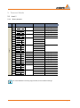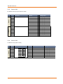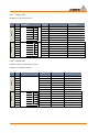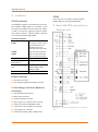
1
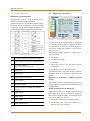
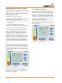
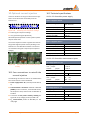
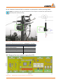
Technical Data Controller for Petersen Coils REG-DPA 1 Wall mounting version 1 Panel-mount housing 1 Standard DIN-rail assembly 1. Application The freely programmable REG-DPA regulator is used in medium and high-voltage grids to control arc suppression coils (Petersen coils) that are adjustable under continuous load. It can also solve all other control, measurement and recording tasks related to the Petersen coil. The optional current injection can deal with all of these side-effects and accurately tune the Petersen coil to the real grid situation. Resistor control (increase residual watt current) Control methods: It contains a freely configurable resistance control to increase the residual watt current supporting fault finding using the cos(ϕ) method. A thermal image of that resistor is computed to protect the same as an independent function unit. 0 Classic Take over control tasks for pulse location The regulator controls Petersen-coils in several ways. Depending on the requirements, the regulator can be set to a percentage or absolute detuning. For overhead transmission grids with high natural unbalance, a certain zero sequence voltage and detuning value can be set to balance between high neutral voltage displacement und right compensation. When an earth fault occurs, the regulator can correct the Petersen coil by the detuning and tune the grid to the resonance. There are a number of ways in which the regulator can control several Petersen coils in a compensation district. The free programmability of the regulator enables it to perform special tasks, such as controlling a pulse cabinet. 0 Optional current injection In some grid configurations, it is possible that the Petersen coil cannot be tuned in the traditional way. For example such situations are: – Very balanced grids (cable grids) – Measuring signal that is heavily distorted by crosstalk (non-linear consumer or generator in the grid area) – Overhead transmission grids with asymmetrical conditions Issue 04/2014 Pulse locating is a method to search for earth faults in the medium voltage grid by introducing a pulse pattern to the fault current. The regulator can be equipped with a background program that controls and monitors the pulse locating unit. This ensures that the conditions for successful pulse locating are met. Control system / Communication The REG-DPA regulator has a system bus (E-LAN) that enables it to communicate with other system devices. A parallel (relay contacts) and serial remote control centre connection are available. The following protocols are available (additional protocols on request): 0 0 0 0 0 0 IEC 60870 - 5 - 101 / 103 / 104 IEC 61850 DNP 3.0 over Ethernet DNP 3.0 MODBUS RTU / MODBUS TCP SPABUS g We take care of it. 2. Characteristics 2.1 Regulator functions Multimaster system architecture The REG-DPA is part of a range of devices that is based on a standard hardware platform. If multiple devices are connected through the system bus E-LAN, every bus participant can be configured or read from a single PC. In addition, several PCs can access individual system participants (multimaster). Figure 2: Regulation of the detuning A change in the grid’s switching status is recognized by a change in the zero sequence voltage. The regulator repositions the Petersen coil while taking into account the configurable conditions to the set detuning current. Figure 1: REG-DPA regulator functions 1 Voltage transducer (zero sequence voltage) 2 Position signal (resistance sensor) for the coil 3 Current transducer (e.g. current through the P-coil) 4 Binary inputs 5 Power supply 6 Display and processing unit 7 Binary outputs 8 Analogue outputs 9 E-LAN connection (2 x RS485 with repeater function) 10 COM1, RS232 11 COM2, RS232 12 COM3, RS485 13 Status - Signal (relay) Page 2 The following data are displayed in addition to the regulator’s status: 0 0 0 0 Coil position Zero sequence voltage Detuning (v) Total active current in the grid over the fault location (Iw) 0 The resonance curve and its parameters The switching status is monitored through a complex evaluation of the zero sequence voltage (value and phase). Regulation to percentage or absolute detuning current: The regulator positions the Petersen coil according to the configured setpoint value and effective positioning tolerance. Special requirements for the 110 kV grid Additional parameters can be taken into account for high-voltage grids, such as a maximum continuous adjacent zero sequence voltage. The following conditions are also taken into account: 0 Value of the allowable zero sequence voltage 0 Compensation limit = Value of the detuning current that may not be exceeded Characteristics Adjusting the Petersen coil during the earth fault: The regulator can be configured so that the Petersen-coil can be corrected by compensation value during an earth fault. Additional corrections can be made through binary inputs. Parallel operation of Petersen coils: A number of methods are available to control Petersen coils that are switched in parallel. 0 Parallel control with communication over E-LAN (master-slave) 0 Parallel control without communication 0 Parallel control with recognition of external grid 2.3 Regulator statistics Statistics mode displays the most important sum times and counters. This information can be used to determine how many tuning procedures were carried out in which time frame, and how many were successfully completed. It also enables you to recognize for how many tuning procedures the P-coil’s adjustment range was insufficient. Statistics mode also records the number of earth faults and increases in residual watt current that were carried out. coupling (only with optional current injection) 2.2 Recorder and logbook function An integrated recorder continuously records the progression of the zero sequence voltage and the coil position. The time line diagram can both be displayed and evaluated on the regulator or on a PC. This integrated ‘grid spy’ enables long-term changes in the zero sequence voltage to be recorded and monitored. The configuration software WinEDC is used to evaluate and archive recorded data on the PC. Figure 4: Statistics Page 1/5 The progression of the zero sequence voltage Uen is also displayed as a line diagram. The time grid (feed rate) for the recording is adjustable. The stored values and the allocated time can be displayed using a keyboard or PC. Figure 3: Recorderview Important events are recorded in a logbook with date and time information and can be displayed on the screen or a PC statistic Characteristics Page 3 We take care of it. 2.4 Resistor control 2.5 Configuration The freely configurable and autonomous resistor control automatically connects a resistor to increase the residual watt current in the event of an earth fault. A resistor’s load is monitored with a ‘thermal image’ whereby the current zero sequence voltage ¬is taken into account when it is connected. The connection is blocked in the event of over temperature. The remaining resistor connections are displayed in the screen until the limit temperature has been reached. The configuration of the regulator is menu driven, and therefore very easy. A recurring connection by transient earth faults can be suppressed. A resistor can be connected manually through a binary input or the remote control system. Figure 7: Regulator Menu The putting into operation of the regulator and its configuration for the P-coil (e.g. linearization of the coil position) is largely automatic. The process’ reactions are continuously monitored and checked for plausibility. Errors are analysed and displayed in the status bar. Additional information and troubleshooting tips can be viewed as an additional menu. Figure 5: Example for the resistor control Figure 6: cycles R:10 = Number of possible resistor Page 4 Characteristics Overload capacity 3. Technical specifications 3.1 Regulations and standards 0 0 0 0 0 0 0 0 0 0 IEC 61010-1 10 A continuous 30 A for 10 s 60 A for 1 s 500 A for 5 ms 3.4 Potentiometer input CAN/CSA C22.2 No. 1010.1-92 IEC 60255-22-1 Position signal (IPos) IEC 61326-1 IEC 60529 IEC 60068-1 8 IEC 60688 IEC 61000-6-2 IEC 61000-6-4 IEC 61000-6-5 3.2 AC voltage inputs AC voltage input (Uen) Transmitter Potentiometer Nominal value Rn 0,2 kΩ, 0,5 kΩ, 1 kΩ, 3 kΩ Measuring voltage ca. 5 VDC Current selectable through jumper (pure) 1 mA (3 kOhm) 5 mA ( 600 Ohm) 10 mA ( 300 Ohm) 20 mA ( 150 Ohm) Error message when sensor breaks or is short circuited or when the voltage of the loop is outside of the measurement range. Zero sequence voltage Uo 0,1V ... 120V Shape of the curve Sinus Frequency range 45....50....60....65 Hz Internal consumption ≤ U / 100 kΩ Binary inputs (BI) Overload capacity 1,2 * 120V Inputs E1 ... E16 2 3.5 Binary Inputs (BI) Control signals Ust im Bereich AC/DC 48 V ... 250 V, Shape of the curve, permissible Rechteck, Sinus AC voltage input (U12) Synchronization voltage U12 0,1V ... 230V Shape of the curve Sinus Frequency range 45....50....60....65 Hz Internal consumption ≤U / 100 kΩ Overload capacity 1,2 * 230V 2 3.3 AC current inputs AC current inputs ( Ip und I2 ) Current range 1A/5A (hardware- und softwaremäßig wählbar) Shape of the curve Sinus Frequency range 45....50....60....65 Hz 48 V...250 V – H - Level – L - Level ≥ 48 V < 10 V Signal frequency DC, 40 ... 70 Hz Input resistance 108 kΩ Potential isolation Optocoupler; each galvanically isolated from each other. Debouncing Software filter with integrated 50Hz filter Internal consumption Technical specifications Page 5 We take care of it. 3.6 Binary outputs (BO) Binary outputs (BO) R 1 ... R13 max. switching frequency Potential isolation Contact load 3.8 Display Display LC – Display 128 x 128 displays graphics Lighting LED, switches off after 15 min ≤ 1 Hz Isolated from all deviceinternal potentials AC: 250 V, 5 A (cosϕ = 1.0) Reference conditions Reference temperature 23°C ± 1 K Switching capacity max. 1250 VA Input quantities UE = 0 ... 120V U12 = 0,1 … 230V IE = 0 ... 1A / 0 ... 5A DC: 30 V, 5 A resistive Auxiliary voltage H = Hn ± 1 % DC: 110 V, 0.5 A resistive Frequency 45 Hz...65 Hz DC: 220 V, 0.3 A resistive Shape of the curve Sinusoidal, form factor 1.1107 Burden (only for Characteristics E91...E99) Rn = 5 V / Y2 ± 1 % Other IEC 60688 - Part 1 AC: 250 V, 3 A (cosϕ = 0.4) DC: 30 V, 3.5 A L/R=7 ms Switching capacity max. 150 W Inrush current 250 V AC, 30 V DC 10 A for max. 4 s Switching operations ≥ 5·10 electrical 5 3.7 Analogue outputs 20 mA - Analogue outputs Quantity See order specifications Output range Y1...Y2 -20 mA...0...20 mA, Y1 and Y2 freely programmable Control limit ± 1.2 Y2 Potential isolation Optocoupler Burden range 0 ≤ R ≤8 V / Y2 Alternating component < 0.5% of Y2 The output can be continuously short-circuited or operated open. The output connections are galvanically isolated from all of the other circuits. Page 6 Technical specifications 3.9 Electrical safety 3.11 Electromagnetic compatibility Electrical safety Electromagnetic compatibility Safety class I Degree of pollution 2 Over-voltage category II and III Category III Category II Input circuits for current and voltage transducer Control circuits, analogue inputs, analogue outputs, power supply, ELAN, COMs EMC requirements EN 61326-1 Equipment class A Continuous, unmonitored operation, industrial area and EN 61000-6-2 and 61000-6-4 Interference emissions Conducted and radiated EN 61326 Table 3 emission EN 61000-6-4 Harmonic currents EN 61000-3-2 Voltage fluctuations and EN 61000-3-3 flicker Operating voltages 50 V 120 V 230 V E-LAN, COM1 ... COM3 Analogue inputs, analogue outputs Inputs 10...50 V Voltage inputs, current inputs Auxiliary voltage, sync voltage for binary inputs (E1...E16, Relay outputs R1...R13), status Conducted and radiated EN 61326 Table 3 emission EN 61000-6-4 Disturbance immunity EN 61326 Table A1 and EN 61000-6-2 ESD IEC 61000-6-5 6 kV/8 kV contact/air Electromagnetic fields IEC 61000-4-3 80 – 2000 MHz: 10 V/m Fast transient IEC 61000-4-4 4 kV/2 kV Surge voltages IEC 61000-4-5 4 kV/2 kV Conducted HF signals IEC 61000-4-6 150 kHz – 80 MHz: 10 V Power-frequency magnetic fields IEC 61000-4-8 100 A/m (50 Hz), continuous 1000 A/m (50 Hz), 1 s Voltage dips IEC 61000-4-11 30% / 20 ms, 60% / 1 s Voltage interruptions IEC 61000-4-11 100% / 5s Damped oscillations IEC 61000-4-12, Class 3, 2.5 kV 3.10 Power supply Stromversorgung Characteristic H1 H2 AC 85...264V - DC 88...280V 18 ...72V Power consumption ≤ 33 VA ≤ 15 W Frequency 50 Hz / 60 Hz - Microfuse T1 250V T2 250V The following applies to all characteristics: Voltage dips of ≤ 40 ms result neither in data loss nor malfunctions. Technical specifications Page 7 We take care of it. 3.12 Climatic conditions 3.14 Mechanical design Ambient conditions Mechanical design Temperature range Housing Sheet steel, RAL 7035 gray Height 288 mm IEC 60068-2-1, - 15 °C / 16 h Width 216 mm Overall depth 114 mm IEC 60068-2-2, + 65 °C / 16 h Mounting depth 87 mm Mass ≤ 3 kg Humid heat constant IEC 60068-2-78 + 40 °C / 93% / 2 days Housing doors with silica glass Front panel Humid heat cyclical IEC 60068-2-30 12+12 h, 6 cycles +55 °C / 93% plastic, RAL 7035 gray, on aluminium supports Transport and storage function Dry cold Dry heat Drop and topple over -15 °C ... +60 °C -25 °C ... +65 °C Control panel cutout – Height – Width 282 mm 210 mm IEC 60068-2-31 100 mm drop height, unpackaged Protection type IP 54 Vibration IEC 60255-21-1, Class 1 Rain Test 3R UL50 Shock IEC 60255-21-2, Class 1 In-panel mounting in conformity with DIN 41494 Part 5 Earthquake resistance IEC 60255-21-3, Class 1 3.15 Optical Interface 3.13 Storage Storage Firmware and recorder data Characteristic S2 Flash storage Device characteris- serial EEPROM with ≥ 1000 k tics and calibration write/read cycles data Other data and recorder data Characteristic S1 SDRAM, battery-backed (plugin lithium battery), backup to flash storage possible The REG-DPA regulator can also be directly connected via a fibre optic cable interface. Sending and receiving devices are available for glass and plastic fibre optic cables. In addition, it can be choose between various mechanical connection possibilities (ST or FSMA connection). Features V13 to V19 give an overview of the various possibilities 3.16 Electrical logical interface Logic level of receiving output : CMOS (Uhmin : > 0,9VCC, Ulmax < 0,1VCC @ Io = 1mA) Logic level of receiving intput: CMOS (Uhmin : > 0,7VCC, Ulmax < 0,3VCC), Schmitt-Trigger Page 8 Technical specifications 3.17 Optical transmitter Product Type Fibre Pmin Pmax 1) 1) [dBm] [dBm] Glass-ST HFBR50/125µm -19,8 Glass-SMA 1414-T NA=0,2 HFBR-1404 λ = 820nm 62,5/125µm -16,0 NA=0,275 -12,8 -9,0 4. General information about the connections The regulator has three circuit boards / connection levels. Level III Level II POF_ST 100/140µm -10,5 NA=0,3 -3,5 200µm HCS -6,2 NA=0,37 +1,8 HFBR1mm POF -7,5 1515B λ = 650nm 200µm HCS -18,0 POF_SMA HFBR1mm POF -6,2 1505C λ = 650nm 200µm HCS -16,9 -3,5 -8,5 0,0 -8,5 3.18 Optical receiver Product Type Fibre Pmin Pmax 2) 2) [dBm] [dBm] Glass-ST HFBR100/140µm -24,0 Glass-SMA 2412-T NA=0,3 HFBR-2402 0 ... 5MBd λ = 820nm -10,0 POF_ST 0,0 HFBR1mm POF -20,0 2515B 0 ... 10MBd 200µm HCS -22,0 λ = 650nm POF_SMA HFBR1mm POF -21,6 2505C 0 ... 10MBd 200µm HCS -23,0 λ = 650nm Level I Figure 8: On level 1 the auxiliary voltage, input voltage and currents, as well as the relay outputs, binary inputs, etc. are connected. Level II contains the hardware for all control system connections is contained. The appropriate connection elements on Level II must be used for RS232 or RS485 connections. If an Ethernet connection is used, the corresponding connection on Level II is also available (must be connected for IEC 61850 or IEC 60870-5-104!). The connection elements for fibre-optic cables (send and receive diodes as ST or FSMA connection) are mounted directly on the flange plate and can be connected there without having to open the device. -2,0 -2,0 -3,4 Figure 9: General information about the connections Internal structure of REG-DPA Fiber optic (ST-connection) Page 9 We take care of it. In total, two connection points are available and they can be equipped with the following modules: Figure 10: Fibre optic (FSMA-connection) Modul 1: 6 binary inputs AC/DC 48V...250V Modul 1: 6 relay outputs Modul 1: 2 x 20 mA- inputs Modul 1: 2 x 20 mA- outputs Level III contains the connections for the individual COM, E-LAN, the analogue inputs and outputs and the PT100 input Furthermore, additional binary inputs and outputs as well as mA inputs and outputs can also be accommodated on Level II. Figure 11: Page 10 Location of the connector terminals General information about the connections 5. Terminal blocks 5.1 Level I 5.1.1 Binary outputs Level I Nr. Description 33 34 35 36 37 38 39 40 41 42 43 44 45 46 47 48 49 50 51 52 53 54 55 56 57 58 59 R3 R4 R5 R2 R1 R6 R7 R8 R9 R10 R11 R6..R11 R13 R12 Function Configuration NOC Terminal NOC Terminal NOC Terminal NCC Terminal Terminal NOC NCC Terminal Terminal NOC NOC NOC NOC NOC NOC NOC Terminal NOC Terminal NCC r NOC Terminal NCC freely programmable freely programmable freely programmable Higher Lower freely programmable freely programmable freely programmable freely programmable freely programmable freely programmable closes at fault Life-contact (Status) opens at fault HAND AUTO All of the REG-DPA’s are freely programmable, but have default settings. Terminal blocks Page 11 We take care of it. Level I 5.1.2 Binary inputs Nr. Description 11 12 13 14 15 16 17 18 19 20 23 24 25 26 27 28 29 30 31 32 Binary inputs Page 12 Configuration E1 E2 Terminal E1..E2 E3 E4 E5 E6 E7 E8 Terminal E3..E8 E9 E10 E11 E12 Terminal E9..E11 E13 E14 E15 E16 Terminal E13..E16 + + + + + + + + + + + + + + + + - Endswitch high Endswitch low freely programmable freely programmable freely programmable freely programmable freely programmable freely programmable freely programmable freely programmable freely programmable freely programmable freely programmable freely programmable freely programmable freely programmable Terminal blocks Level I 5.1.3 Une, USync, Ip and auxiliary voltage Nr. Description Configuration 1 2 4 5 7 8 21 22 126 127 128 Synchronisation voltage (Usync) Zero sequence voltage Une Stromeingang Ip Auxiliary voltage UH Coil position Ipos L1 L2 n e k l L/(+) N/(-) Pot + Us Pot- U12 UNE Ip UH 5.2 Level II (additional inputs and outputs) 5.2.1 Scada module Nr. Descripiton Function Configuration Scada module IEC Level II LON DNP 3.0 SPA Bus Modbus 5.2.2 Feature C01 Module 1 6 additional binary inputs AC/DC 48…250V Nr. Description Function 100 101 102 103 104 105 106 Binary inputs E17 E18 E19 E20 E21 E22 Terminal E17..E22 Terminal blocks Configuration + + + + + + - freely programmable freely programmable freely programmable freely programmable freely programmable freely programmable Page 13 We take care of it. 5.2.3 Feature C02 Module 1 Module 1 12 additional binary inputs AC/DC 48…250V Nr. Description Function 100 101 102 103 104 105 106 107 108 109 110 111 112 113 Binary inputs E17 E18 E19 E20 E21 E22 Terminal E17..E22 E23 E24 E25 E26 E27 E28 Terminal E23..E28 Binary inputs Configuration + + + + + + + + + + + + - freely programmable freely programmable freely programmable freely programmable freely programmable freely programmable freely programmable freely programmable freely programmable freely programmable freely programmable freely programmable 5.2.4 Feature C03 6 additional relays (NO contacts) Module 2 Nr. 100 101 102 103 104 105 106 Page 14 Description Function R14 R15 R16 R17 R18 R19 R14..R19 Configuration NOC NOC NOC NOC NOC NOC Terminal freely programmable freely programmable freely programmable freely programmable freely programmable freely programmable Terminal blocks 5.2.5 Feature C04 12 additional relays (NO contacts) Module 2 Module 2 Nr. Description 100 101 102 103 104 105 106 107 108 109 110 111 112 113 Function R14 R15 R16 R17 R18 R19 R14..R19 R20 R21 R22 R23 R24 R25 R20..R25 Configuration NOC NOC NOC NOC NOC NOC Terminal NOC NOC NOC NOC NOC NOC Terminal freely programmable freely programmable freely programmable freely programmable freely programmable freely programmable freely programmable freely programmable freely programmable freely programmable freely programmable freely programmable 5.2.6 Feature C05 6 additional binary inputs AC/DC 48…250V Module 2 Module 1 6 additional relays (NO contacts) Nr. Description Function 100 101 102 103 104 105 106 107 108 109 110 111 112 113 Binary inputs E17 E18 E19 E20 E21 E22 E17..E22 R14 R15 R16 R17 R18 R19 R14..R19 Terminal blocks Configuration + + + + + + Terminal (-) NOC NOC NOC NOC NOC NOC Terminal freely programmable freely programmable freely programmable freely programmable freely programmable freely programmable freely programmable freely programmable freely programmable freely programmable freely programmable freely programmable Page 15 We take care of it. 5.2.7 Feature C06 2 additional analogue 20mA inputs Module 3 Nr. 100 101 102 103 Description Function Analogue input E10 Analogue input E11 Configuration + + + 5.2.8 Feature C07 4 additional analogue 20mA inputs Module 3 Module 3 Nr. Description 100 101 102 103 104 105 106 107 Function Analogue input E10 Analogue input E11 Analogue input E12 Analogue input E13 Configuration + + + + + + 5.2.9 Feature C08 2 additional analogue 20mA outputs Module 3 Nr. 100 101 102 103 Description Function Analogue output A10 Analogue output A11 Configuration + + + 5.2.10 Feature C09 4 additional analogue 20mA outputs Module 3 Module 3 Nr. 100 101 102 103 104 105 106 107 Page 16 Description Function Analogue output A10 Analogue output A11 Analogue output A12 Analogue output A13 Configuration + + + + + + Terminal blocks Figure 12: Overview of default configuration REG-DPA 6. Block diagrams Block diagrams Page 17 We take care of it. 7. Housing technology Figure 13: Mechanical dimensions REG-DPA Figure 14: Mechanical dimensions, Panel mount housing Page 18 Housing technology Figure 15: Mechanical dimensions, standard DIN-rail assembling Figure 16: Mechanical dimensions, wall-mounting version Housing technology Page 19 We take care of it. 8. Interfaces COM3 RS232 Interfaces Use to connect ≤ 15 random interface modules (ANA-D, BIN-D) to the regulator REG-DPA. The REG-DPA regulator has two RS 232 serial interfaces (COM1, COM2); COM 1 is accessible on the front panel and COM 2 on the terminal strip. COM 2 is used to connect the regulator system to higher level control systems. Customer-specific protocols can be implemented through COM 2. 9. Basic REG-DPA connection to Petersen coil Connection elements Connection element COM 1 Pin strip, sub min D on the front of the device, pin allocation as PC multipoint terminal connector COM1S plug connector (Level III) COM 2 plug connector (Level III) plug connector (Level III) Connection options PC, terminal, modem, PLC Number of data bits/protocol Parity 8, even, off, odd Transmission rate bit/s 1200, 2400, 4800, 9600, 19200, 38400, 57600, 76800, 115000 Handshake RTS / CTS or XON / XOFF RS485 interfaces 0 Connection to E-LAN 0 Dual interface RS 485 with repeater function E-LAN (Energy Local Area Network) Characteristics 0 0 0 0 0 0 0 0 255 addressable participants Multi-master structure Integrated repeater function Open ring, bus or a mixture of bus and ring Protocol is based on SDLC/HDLC frames Transmission rate 62.5 kbit/s or 125 kbit/s Frame length 10 ... 30 Bytes Figure 17: coil Connecting REG-DPA to a Petersen medium-throughput approx. 100 frames/s Page 20 Interfaces 10. Optional current injection 10.2 Technical specifications There are situations in the grid in which classic regulation cannot be used to successfully tune the Petersen coil. 10.2.1 CCI Controller power supply 2005-04-06 01:33:53 Uo / V sek 3 Power supply AC Version Nominal voltage (Un) 100…240 V AC 100…350 V DC Overload capacity 1.3 * Un Overload for 1s 2 * Un Power consumption ≤ 15 VA Frequency DC or 50/60 Hz Voltage dip (100%) < 50 ms 2 1 0 00:00:00 00:00:00 Figure 18: 00:00:00 00:00:00 00:00:00 00:00:00 00:00:00 00:00:00 00:00:00 00:00:00 00:00:00 00:00:00 Flickering zero sequence voltage 0 Flickering zero sequence voltage 0 Very symmetrical grids (balanced) We developed the optional current injection specifically for these cases. The current injection creates a signal that is fed into the grid through the power auxiliary winding in the Petersen coil. The REG-DPA calculates a resonance curve based on the grid’s response (zero sequence voltage). Power supply DC Version Nominal voltage (Un) 110 V DC ±20% Overload capacity 1.3 * Un Overload for 1s 2 * Un Power consumption ≤ 15 VA Voltage dip (100%) < 50 ms 10.2.2 CCI Controller measurement inputs AC voltage inputs U1...U3 Figure 19: Current feed-in controller (CCI Controller) 10.1 Four connections to retrofit the current injection The following connections have to be established if the current feed-in is to be retrofitted: 0 Power supply 230 V AC (internally fused with 16 Voltage range Unom with jumper without jumper 0…120 V 0…500 V Shape of the curve Sine Frequency range 45....50....55 Hz Input resistance with jumper without jumper 60 280 kΩ kΩ Permanent overload Unom *1.2 A) 0 Communication connection between REG-DPA (COM3) and CCI controller; 4-wire RS 485 shielded telephone cable; distance CCI to REG-DPA up to 200 m 0 Connection to the power auxiliary winding designed for 16 A; voltage-proof up to 500 V AC 0 Uen measurement parallel to REG-DPA; Ex. see AC voltage inputs L1...L3 Voltage range Unom 0...250 V Shape of the curve Sine Frequency range 45....50....55 Hz Input resistance 140 Permanent overload Unom *1.2 kΩ next pages Optional current injection Page 21 We take care of it. 10.2.4 CCI Controller binary inputs AC power inputs I1...I3 Current range Inom with jumper without jumper 0...5 A 0...25 A Shape of the curve Sine Frequency range 45....50....55 Hz Power consumption ≤ 0.1 VA Permanent overload Inom *1.2 Permanent ≤ 10s ≤ 1s ≤ 5ms 10 A 30 A 100 A 500 A 10.2.3 CCI Controller binary inputs AC and DC H - Level E1…E2 E3…E4 E5…E6 max. switching frequency ≤ 1 kHz Contact load AC:250 V, 5 A (cos = 1.0) AC:250 V, 3 A (cos = 0.4) DC switching capacity: 250 VDC: <= 75 W 30 VDC: <= 150 W Switching operations > 10 electrical Potential isolation galvanically isolated from all device-internal potentials 5 10.3 Inductance (derating) Inductance Binary inputs E1...E6 Input voltage Relay outputs < 80 V AC/DC < 10 V AC/DC < 65 V AC/DC Quantity 2 Inductance 104 mH Nominal frequency: 50 Hz Voltage range up to 550 V AC L - Level E1…E2 E3…E4 E5…E6 < 40 V AC/DC < 5 V AC/DC < 45 V AC/DC Signal frequency DC…65 Hz Potential isolation Optocoupler Input resistance E1, E2 E3, E4 E5, E6 Potential isolation Page 22 ca. 100 kΩ ca. 5 kΩ ca. 100 kΩ Optocoupler; all inputs galvanically isolated from each other Optional current injection 10.4 Connection options for current injection to REG-DPA and Petersen coil A magnetic coupling between the power auxiliary winding and the measuring transducer for Uo directly on the Pcoil can affect the calculation results. We recommend the following interconnection options when measuring Uo in conjunction with the current injection. Figure 20: Example of in-panel mounting: Current injection mounted directly into the motor drive box of the Petersen coil 10.4.1 Connections to measure Uo at open delta winding Figure 21: REG-DPA connection, current injection and Petersen coil; Optional current injection Page 23 We take care of it. 10.4.2 Connections to measure Uo through separate/external measuring transducer Figure 22: Uo measurement over external or remote voltage transducer 10.4.3 Connections for current injection when the power auxiliary winding is missing In this case, the power section of the current feed-in is connected to a separate feed-in transducer. Figure 23: Page 24 External power auxiliary winding and use of internal voltage transducer for the Petersen coil Optional current injection 10.4.4 Example of external feed-in transducer as spare power auxiliary winding (PAW) NOTE! This transducer can only be used with the current injection. It is not a full replacement for a standard power auxiliary winding. Figure 24: Spare power auxiliary winding (PAW) for current injection The technical data for the transducer for a 20 kV grid are as follows: Technical data for transducer for spare PAW Type single-phase ⁄ Primary nominal voltage Secondary nominal voltage Class 500 V 3 Nominal output/Nominal burden 1000 VA 10.5 Design of current injection controller (CCI) Figure 25: Dimensions of current feed-in controller (CCI) Optional current injection Page 25 We take care of it. PE -X5 1 2 Auxiliary Power E2 -X6 1 2 E1 Thyristor control 12V 3 E4 4 E3 5 3 4 5 6 7 8 9 -X2 1 6 -X7 1 -X1 1 2 Coil Position 2 3 E6 4 2 5 3 6 E5 7 4 5 R7 8 6 7 R5 -X3 1 8 9 2 R4 3 10 4 -X8 1 2 3 4 5 6 R3 Thyristor control 5 6 R2 R1 7 8 -X9 1 -X3 1 2 3 4 2 Voltage Measurment 3 COM 3 5 4 6 5 -X10 1 6 2 3 4 Current Measurement 5 6 Figure 26: Page 26 Terminal connections CCI Optional current injection 10.6 Terminal configuration CCI 10.6.1 Terminal strip – X1 binary inputs 10.6.4 Terminal strip –X4 COM3 (RS 485) connection Pin Relay 6 Type X4:1 Function Comments GND_1a Isolated Pin Type Function Comments X4:2 DO Tx + X1:1 Input Root E1..E2 Default: OFF X4:3 DO Tx - E2: SE-FUSE X4:4 DI Rx + Fuse monitoring max. 110 V DC X4:5 DI Rx - E5: End switch low Default: OFF X1:2 Input X1:3 Input X1:4 X4:6 NC GND_1 Isolated NC X1:5 Relay R6: Binary output Pot. 12 V DC X1:6 Relay +12 V Output Pot. 12 V DC X1:7 Input E4: Binary input max. 12 V DC X1:8 Input E3: Binary input max. 12 V DC X1:9 Input Root E3...E4 10.6.5 LEDs on current feed-in controller LED COM1 1 2 3 10.6.2 Terminal strip – X2 potentiometer 4 5 Pin Type Function Comments X2:1 AO Potentiometer + ca. +3 V X2:2 AI Potentiometer loop X2:3 AO Potentiometer - X2:4 X2:5 Reset Figure 27: LED definitions current injection controller CCI NC AI X2:6 X2:7 6 reserved LED reserved AO X2:8 reserved +/- 5 V reserved 1 10.6.3 Terminal strip – X3 AC switch (Thyristor) 2 Pin Function Usync measurement << 15 V Usync Thyristors << 30V 3 Status OK Status error 0 RED 0 RED 0 Function Comments 4 Current injection active GREEN X3:1 L1+ ca. +3 V 5 PLL synchronized GREEN X3:2 (L2+) X3:3 L1- 6 Status current injection controller (CCI) GREEN flashing X3:4 (L2-) X3:5 Phase Type NC 10.6.6 PE Pin X3:6 X3:7 +5 V X3:8 GND Optional current injection I 1 Typ e Function Comments PE Protective earth Page 27 We take care of it. 10.6.7 Terminal strip – X5: Power supply 10.6.10 Pin Pin Type Function Comments X8:1 Relay R3: opens upon failure Default: OFF X8:2 Relay R3: closes upon failure 10.6.8 Terminal strip – X6: Synchronisation voltage Thyristor block X8:3 Input E5: End switch low Default: OFF X8:4 Relay R7: freely programmable Default: OFF Pin Comments X8:5 UL1: 230 V AC X8:6 Type Function X5:1 L1 / +110 V DC X5:2 N / -110 V DC Type Function X6:1 Connection L1 X6:2 Connection N X6:3 Not used X6:4 Not used X6:5 Not used X6:6 Not used Comments Supply voltage Pin Type Function Comments 0…100…500 V AC Cabinets that we prefabricate come equipped with the connections. X9:2 Usync_2 Default: 500 V X9:3 Une_GND 0…100…500 V AC X9:4 Une Default: 100 V X9:5 Uod_Tr_GND 0…100…500 V AC Default: OFF X9:6 Uod_Tr 10.6.12 Terminal strip – X10 current inputs Type Function Comments X7:2 Input Root end switch signal (E5..E6) X7:3 Input E5: End switch low Default: OFF Relay R7: freely programmable Default: OFF X7:5 R7: Root Relay X7:7 R5: Motor lower Relay R4: Motor higher X7:9 R4: Root X7:10 R4: Not used Default: 100 V Pin Default: OFF R5: Root (Only for extended algorithm) Type Function Comments X10:1 PE X10:2 I1_a s1_ ICI 0…1…5…10…25 A AC X10:3 I1_b s2_ ICI Default: Current measured directly at CCI output X10:4 I2_a s1_ IS 0…1…5…10…25 A AC X10:5 I2_b s2_ IS (Only for extended algorithm) X10:6 I3_a s1_ IF 0…1…5…10…25 A AC X10:7 I3_b s2_ IF (Only for extended algorithm) Default: OFF Default: OFF Note: The connections to X7 and X8 are redundant to the connections on the REG-DPA. The wiring for the end switch and the motor contacts are directly done on the REG-DPA. This is why the connections for the current injection controller so not have to be configured. Page 28 Default: OFF Usync_1 E6: End switch high X7:8 R5: Motor lower X9:1 Input X7:6 Relay Note: X7:1 X7:4 R7: Root 10.6.11 Terminal strip – X9 inputs for voltage measurement 10.6.9 Terminal strip – X7 relay range 1 Pin Terminal strip – X8 relay range 2 Optional current injection 11. WinEDC configuration and configuration software The WinEDC software is used to configure and program the system. It can be used in three different modes. In Panel mode, the regulator can be displayed and controlled using the mouse. All of the settings, which can be made directly on the regulator using its membrane keyboard, can be carried out centrally in WinEDC. Parameter mode enables each of the components to be quickly and easily configured. The parameters are set in a straightforward tree structure, saved for later use or transferred to a bus participant. This guarantees an easy and clear operation and is particularly useful when E-coil controllers and EOR-D earth fault detection relays in the REGSys™product line are used together in a plant component. Terminal mode enables direct communication with the system. The WinEDC Terminal is much easier to use than conventional terminal programs and makes programming the system a lot easier. WinEDC runs on all versions of Windows from Windows95 to Windows 8 in 32-bit and 64-bit. Figure 28: EORSys product range deployment WinEDC configuration and configuration software Page 29 We take care of it. 12. Order specifications Please observe the following when placing an order: 0 0 0 0 Only one unit can be ordered for codes with the same capital letter. When a code's capital letter is followed by the number 9, additional information in plain text is required. When a code's capital letter is followed only by zeroes the code may be omitted. X characteristics such as XL1 cannot be combined with all of the other characteristics. Please read the notes and explanations. Characteristic Code Resonance regulator for Petersen coil REG-DPA resistance control, parallel control, Long-term recording and log book 16 binary inputs (freely programmable) 12 relay outputs (freely programmable), status relay, Current input (1 A or 5 A), COM 1, COM 2, COM 3 to connect a current injection WinEDC configuration software and connection cable (null modem) Note: COM2 is used for protocol communication. Hence available for external use without interface cards only Model 0 In-panel mounting housing/ Wall-mounting housing (H x B x T) 307 x 250 x 102 mm 0 DIN-Rail adapter B01 B02 Serial interface COM1 0 RS232 0 USB I0 I1 Power supply 0 external AC 85 V...110 V...264 V / DC 88 V...220 V...280 V 0 external DC 18 V...60 V...72 V H1 H2 Parallel control 0 communication over E-LAN 0 Distributed controller and communication without E-LAN K0 K1 Measurement input 0 additional current channel I2 (1 A or 5 A) X18 Analogue outputs 0 without 0 (please specify measurement range or scaling when placing the order) – Output 1: Zero sequence voltage Uo – Output 2: Position of Petersen coil Ipos – Output 3: Current through the P-coil Ip – with two analogue inputs, freely configurable. 0 two analogue inputs, freely configurable (via background program). 0 random combination of modules Page 30 E00 E90 E91 E900 Order specifications Characteristic Code Control system connection 0 0 0 0 0 0 0 0 0 0 0 0 0 0 0 0 0 0 0 without (continue with characteristic "L") XW00 IEC 60870-5-104/RJ45 (continue with characteristic "G") XW90 IEC 60870-5-104 with Fiber Optic-connection (continue with characteristic "G") XW92 IEC 61850/RJ45 (continue with characteristic "G") XW91 IEC 61850 with Fibre Optic-ST connection (continue with characteristic "G") XW93 IEC 61850 with Fibre Optic-LC connection (continue with characteristic "G") XW93.1 IEC 61850 with 2xRJ45 connection (continue with characteristic "G") XW94 IEC 61850 with 2xFibre Optic ST connection (continue with characteristic "G") XW95 IEC 61850 with 2xFibre Optic-LC connection (continue with characteristic "G") XW95.1 IEC 61850 with 1xRJ45 und 1xFibre Optic-ST connection (continue with characteristic "G") XW96 IEC 61850 with 1xRJ45 und 1xFibre Optic-LC connection (continue with characteristic "G") XW96.1 DNP 3.0 via Ethernet with 1xRJ45 connection (continue with characteristic "G") XW97 DNP 3.0 via Ethernet with 2xRJ45 connection (continue with characteristic "G") XW94.1 DNP 3.0 via Ethernet with 1xFibre Optic connection (continue with characteristic "G") XW98 DNP 3.0 via Ethernet with 1xFO-LC connection (continue with characteristic "G") XW98.1 DNP 3.0 via Ethernet with 2xFO-ST connection (continue with characteristic "G") XW95.2 DNP 3.0 via Ethernet with 2xFO-LC connection (continue with characteristic "G") XW95.3 DNP 3.0 via Ethernet with 1xRJ45;1xFO-ST connection (continue with characteristic "G") XW96.4 DNP 3.0 via Ethernet with 1xRJ45;1xFO-LC connection (continue with characteristic "G") XW96.5 Note: If you want a differing protocol for delivery, please choose an additional hardware variant "XWxx" (then continue with feature "Vxx"). Inegrated protcol interface (IEC 60870-5-101/103, DNP…) 0 without (continue with characteristic "G") 0 to connect the REG-DPA to a control center 0 to connect several devices to a control center (REG-DPA/D/DA/DP etc.) L0 L2 L9 Note: Characteristic L9 can only be combined with Z15..Z19 Connection type: 0 Copper – RS 232 – RS 485 2-wire operation only 0 Fibre optic cable with FSMA connection technology, incl. fibreglass module – Fibreglass (Wave length 800...900 nm, range 2000 m) – Plastic (wave length 620...680 nm, range 50 m) 0 Fibre optic cable with ST connection technology, incl. fibreglass module – Fibreglass (Wave length 800...900 nm, range 2000 m) – Plastic (wave length 620...680 nm, range 50 m) Order specifications V10 V11 V13 V15 V17 V19 Page 31 We take care of it. Characteristic Code Protocol – – – – – – – – – – – – IEC 60870-5-103 for ABB Z10 IEC 60870-5-103 for Areva Z11 IEC 60870-5-103 for others Z90 IEC 60870-5-101 for ABB Z15 IEC 60870-5-101 for IDS Z17 IEC 60870-5-101 for SAT Z18 IEC 60870-5-101 for Siemens (LSA/SAS) Z19 IEC 60870-5-101 für others Z91 DNP3 Z20 SPABUS Z22 Modbus RTU Z23 DCF Simulation via NTP and / or E-LAN extansion via Ethernet (CSE) DCF / E-LAN Note: only for IEC-61850 – other protocols on request User Manual 0 0 0 0 0 German G1 English G2 Russian G6 Czech G8 other G9 Display language 0 0 0 0 0 0 same as the operating manual A0 German A1 English A2 Russian A6 Czech A8 other A9 Page 32 Order specifications ACCESSORIES CODE Current injection with two fixed frequencies CIF (Supply voltage AC 230 V) Peak current injection with two fixed frequencies HPCI with additional use of pulse locating (Supply voltage AC 230 V) consists of Thyristor actuator, controller and inductance on mounting panel for 19” cabinet mounting C1 C1 consists of Thyristor actuator, controller and inductance in standard mounting for indoor installation ca. 800 x 800 x 300 mm C2 C2 consists of Thyristor actuator, controller and inductance in standard mounting for outdoor installation ca. 800 x 800 x 300 mm C3 C3 consists of Thyristor actuator, controller and inductance in standard mounting for outdoor installation (wall mounting) ca. 800 x 800 x 300 mm C4 C4 C9 C9 Housing version is negotiable! NOTE! The current injection can only be used without restrictions if the measurement for the zero sequence voltage and the current are derived from the coil’s primary winding. This means that the zero sequence voltage should not be measured on the E-coil itself. ACCESSORIES CODE Female multipoint connector 1 (electrical connector model F) Female multipoint connector (for power input with advanced contacts) Female multipoint connector 3 (mixed connector model F24 + H7) Dummy panel 28 TE Dummy panel 14 TE Dummy panel 7 TE Dummy panel 8 TE PC connection cable (null-modem cable) Modem connection cable 1 pack microfuses T2 L 250 V Time synchronisation: Radio clock DFC 77 111.9024.01 GPS radio clock NIS time, RS 485, Uh: AC 85…110 V…264 V / DC 88 V…220 V…280 V 111.9024.45 GPS radio clock NIS time, RS 485, Uh: DC 18…60 V…72 V 111.9024.46 GPS radio clock NIS time, RS 232, Uh: AC 85…110 V…264 V / DC 88 V…220 V…280 V 111.9024.47 GPS radio clock NIS time, RS 232, Uh: DC 18…60 V…72 V 111.9024.48 Communication: Develo MicroLink 56Ki analogue modem, DIN rail device incl. 230 V AC power supply 111.9030.03 TCP/IP adapter 10 Mbit REG-COM; DIN rail device including power supply 230 V AC A01 TCP/IP adapter 10 Mbit REG-COM; plug-in module 8TE, 3HE; A02 Power supply AC 85…110 V…264 V / DC 88 V…220 V…280 V TCP/IP adapter 10 Mbit REG-COM; plug-in module 8TE, 3HE; A03 Power supply DC 18…60 V…72 V Order specifications Page 33 We take care of it. Notes Seite 34 Notes Notes Notes Seite 35 A. Eberle GmbH & Co. KG Frankenstr. 160 D-90461 Nuremberg Tel.: +49 (0) 911 / 62 81 08-0 Fax: +49 (0) 911 / 62 81 08 99 E-Mail: [email protected] http://www.a-eberle.de Your sales partner: _________________________________ Copyright 2014 by A. Eberle GmbH & Co. KG Subject to change without prior notice. Regler für Petersen-Spulen – REG-DPAA